Language selection

Search

Patent 2253101 Summary

Third-party information liability

Some of the information on this Web page has been provided by external sources. The Government of Canada is not responsible for the accuracy, reliability or currency of the information supplied by external sources. Users wishing to rely upon this information should consult directly with the source of the information. Content provided by external sources is not subject to official languages, privacy and accessibility requirements.

Claims and Abstract availability

Any discrepancies in the text and image of the Claims and Abstract are due to differing posting times. Text of the Claims and Abstract are posted:

  • At the time the application is open to public inspection;
  • At the time of issue of the patent (grant).
(12) Patent Application: (11) CA 2253101
(54) English Title: METHOD AND APPARATUS FOR ENHANCING THE DISSOLUTION OF A GAS IN A LIQUID
(54) French Title: METHODE ET APPAREIL POUR AUGMENTER LA DISSOLUTION D'UN GAZ DANS UN LIQUIDE
Status: Deemed Abandoned and Beyond the Period of Reinstatement - Pending Response to Notice of Disregarded Communication
Bibliographic Data
(51) International Patent Classification (IPC):
  • B01J 3/00 (2006.01)
  • A61L 2/20 (2006.01)
  • C01B 13/10 (2006.01)
  • C02F 1/78 (2006.01)
(72) Inventors :
  • CONRAD, WAYNE (Canada)
  • CONRAD, HELMUT GERHARD (Canada)
  • SZYLOWIEC, TED (Canada)
(73) Owners :
  • FANTOM TECHNOLOGIES INC.
(71) Applicants :
  • FANTOM TECHNOLOGIES INC. (Canada)
(74) Agent: SMART & BIGGAR LP
(74) Associate agent:
(45) Issued:
(22) Filed Date: 1998-11-09
(41) Open to Public Inspection: 2000-05-09
Availability of licence: N/A
Dedicated to the Public: N/A
(25) Language of filing: English

Patent Cooperation Treaty (PCT): No

(30) Application Priority Data: None

Abstracts

English Abstract


A process for compressing a liquid and a gas comprises
introducing at least one gas and at least one liquid into a prandtl
layer pump and passing the gas and the liquid through the prandtl
layer pump to obtain a liquid/gas mixture.


Claims

Note: Claims are shown in the official language in which they were submitted.

-6-
WE CLAIM
1. An apparatus comprising a prandtl layer pump, an inlet
port for introducing at least one gas and at least one liquid to the
prandtl layer pump and an outlet port for removing the resultant
liquid/gas mixture from the prandtl layer pump.
2. The apparatus as claimed in claim 1 further comprising
a depressurization zone downstream from the prandtl layer pump.
3. The apparatus as claimed in claim 2 wherein the
gas/liquid mixture is rapidly depressurized as it enters the
depressurization zone.
4. The apparatus as claimed in claim 1 wherein the
prandtl layer pump comprises a plurality of discs and a catalyst is
applied to at least a portion of one of the discs.
5. The apparatus as claimed in any of the forgoing claims
wherein a catalyst is provided in the depressurization zone.
6. An apparatus comprising a prandtl layer pump, an inlet
port for introducing at least two gases and at least one liquid into the
prandtl layer pump and an outlet port for removing a mixture of
the liquid and the gases wherein the liquid is not reactive with the
gases.
7. The apparatus as claimed in claim 6 further comprising
a depressurization zone downstream from the prandtl layer pump.
8. The apparatus as claimed in claim 7 wherein the
gas/liquid mixture is rapidly depressurized as it enters the
depressurization zone.
9. The apparatus as claimed in claim 6 wherein the
prandtl layer pump comprises a plurality of discs and a catalyst is
applied to at least a portion of one of the discs.
10. The apparatus as claimed in claim 4 or 9 wherein a
catalyst is in the form of a fluid.

-7-
11. The apparatus as claimed in any of the forgoing claims
wherein the inlet port comprises at least two venturi, at least one
gas being introduced through one of the venturi into the prandtl
layer pump and the liquid being introduced through the other
venturi into the prandtl layer pump.
12. A process for compressing a liquid and a gas comprising
introducing at least one gas and at least one liquid into a prandtl
layer pump and passing the gas and the liquid through the prandtl
layer pump to obtain a liquid/gas mixture.
13. The method as claimed in claim 12 further comprising
the step of passing the liquid/gas mixture through a
depressurization zone to obtain a liquid/gas mixture at a reduced
pressure.
14. The method as claimed in claim 13 wherein the
liquid/gas mixture is rapidly depressurized.

Description

Note: Descriptions are shown in the official language in which they were submitted.


, CA 02253101 1998-11-09
Title: METHOD AND APPARATUS FOR ENHANCING THE
DISSOLUTION OF A GAS IN A LIQUID
FIELD OF THE INVENTION
This invention relates of a method for dissolving a gas
into a liquid. The gas may be present either by itself or in
combination with one or more other gasses and/or a liquid.
Further, the liquid into which the gas is to be dissolved may be
present by itself or may also have one or more liquids and/or one or
more other gases associated therewith.
BACKGROUND OF THE INVENTION
In many applications, it is desirable to dissolve a gas
into a liquid. Various different apparatus have been developed in
the past for dissolving gases into liquids. Examples of such
techniques include the use of a sparger, venturi or other inlet port
to introduce a gas into a liquid and allow the gas to percolate
upwards through the liquid. It has also been known to pass a liquid
and a gas through a pump so as to intimately mix the liquid and the
gas to obtain a gas liquid mixture.
One disadvantage of these techniques is that only a
limited amount of the gas is dissolved or exposed to the liquid.
Further, if a pump is used, only limited pressures may be exerted on
the liquid/gas mixture in order to prevent cavitation. In order to
obtain higher dissolution efficiencies, the process must be repeated.
This may be achieved by recycling the undissolved gas and recycling
it through the process.
BRIEF SUMMARY OF THE INVENTION
In accordance with the instant invention, there is
provided a method for dissolving a gas into a liquid comprising
introducing a stream of the gas which is to be dissolved in a liquid,
together with the liquid, into a prandtl layer pump. The pump

CA 02253101 1998-11-09
-2-
compresses the liquid and the gas together so as to enhance the
dissolution of the gas into the liquid. The increased pressure which
can be applied to a liquid/gas mixture by means of the prandtl layer
pump promotes the dissolution of the gas into the liquid.
In accordance with another embodiment, the resultant
gas/liquid mixture is passed to an expansion zone (i.e. a
decompression zone) wherein the pressure to which the liquid/gas
mixture is exposed is rapidly reduced. The rapid depressurization
allows at least some of the dissolved gas to come out of solution to
form a suspension of ultra-fine bubbles (e.g. 1-5~,).
One advantage of the instant invention is that, by the
use of a prandtl layer pump, high pressure may be applied to a
liquid/gas mixture without risk of cavitation.
Another advantage of the instant invention is that
intimate contact is obtained between the gas and the liquid thus
promoting the dissolution of the gas into the liquid. Further, if the
gas/liquid mixture is rapidly depressurized, then a mixture
containing an ultra fine dispersion of gas bubbles in the liquid may
be obtained.
BRIEF DESCRIPTION OF THE DRAWINGS
These and other advantages of the instant invention
may be more fully and particularly understood in connection with
the following description of a preferred embodiment of the
invention in which:
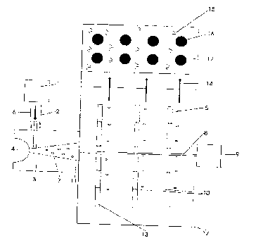
Figure 1 a schematic diagram of an apparatus according
to the instant invention; and,
Figure 2 is an alternate embodiment of a schematic
diagram of the apparatus of Figure 1.
DETAILED DESCRIPTION OF THE PREFERRED EMBODIMENT

CA 02253101 1998-11-09
-3-
In the preferred embodiment shown in Figure 1, a fluid
4 is drawn through a venturi 3 by means of a prandtl layer pump 17.
The prandtl layer pump 17 consists of a series of flat plates 5 which
are connected to a shaft 8 which is in turn connected to a motor 9
which provides the motive force to rotate the plates 5. The rotation
of the plates 5 causes the fluid 4 to be drawn through the venturi 3
which in turn causes the gas 6 to be drawn from the gas source 1
through tube 2 and into the venturi 3. The gas 6 is drawn into the
fluid 4 in such a manner as to form small gas bubbles 7 in the fluid
flow stream. The gas laden fluid stream 11 is drawn through
openings 10 in the plates 5. A catalyst layer 13 may optionally be
applied to the surface of the plates 5 so as to enhance the reaction of
constituents of the gas 6 with constituents of the fluid 4.
As the fluid is forced outwards on a radial serpentine
path along the rotating plates 5 the pressure of the fluid increases
thereby increasing the dissolution of the gas 6 into the liquid 4. This
increase in the pressure of the fluid is possible because unlike
conventional vane or centrifugal pumps, the prandtl layer pump
will not be cavitated by the presence of the gas. The prandtl layer
pump may create a force of, for example, up to 100 psig and, more
preferably up to 250 psig.
The pressurized gas and liquid mixture 14 may then be
passed into an expansion zone 12 wherein the pressure in the gas
and liquid mixture 14 is reduced and preferably rapidly reduced. The
liquid/gas mixture in the expansion zone may be at a pressure of,
for example, 30-60 psig. This depressurization may occur in under 2
seconds, preferably under 1 second and, most preferably, is
effectively instantaneous upon the liquid/gas mixture entering
expansion zone 12. This depressurization allows the dissolved gas to
come out of solution to form a suspension of many ultra-fine (eg. 1
micron to 5 micron) bubbles 15 which effectively reacts with the

CA 02253101 1998-11-09
-4-
constituents of the fluid.
Optionally, a catalyst or catalysts 16 is placed within the
expansion zone 12 to enhance the reaction between constituents of
the gas and the liquid.
In a second embodiment shown in Figure 2, a fluid 4 is
drawn through a venturi 3 and a second venturi 20 by means of a
prandtl layer pump 17. The prandtl layer pump 17 consists of a
series of flat plates 5 which are connected to a shaft 8 which is in
turn connected to a motor 9 which provides the motive force to
rotate the plates 5. The rotation of the plates 5 causes the fluid 4 to be
drawn to venturi 3 and through venturi 20.This in turn causes the
gas 6 to be drawn from the gas source 1 through tube 2 and into the
venturi 3 and also causes the gas 19 to be drawn from the gas source
22 through the tube means 18 and into the venturi 20. The gases 6
and 19 are drawn into the fluid 4 in such a manner to form small
gas bubbles 7 and 21 to form in the respective streams of the fluid 4.
The gas laden fluid stream 11 formed by the combination of the
fluid from venturis 3 and 20, is drawn through openings 10 in the
plates 5. A catalyst layer 13 may optionally be applied to the surface
of the discs 7 so as to enhance the reaction of constituents of the
gases 6 and 19 with each other and/or with constituents of the fluid
4.
As the fluid is forced outwards on a radial serpentine
path along the rotating plates 5 the pressure of the fluid increases
thereby increasing the dissolution of the gases 6 and 19 into the
liquid 4. This increase in the pressure of the fluid is possible because
unlike conventional vane or centrifugal pumps, the prandtl layer
pump will not be cavitated by the presence of the gas.
The pressurized gas and liquid mixture 14 may then be
passed into an expansion zone 12 wherein the pressure in the
mixtures of gases and liquid 14 is reduced and preferably rapidly

CA 02253101 1998-11-09
-5-
reduced. This depressurization allows the dissolved gases to come
out of solution to form a suspension of many ultra-fine (eg. 1
micron to 5 micron) bubbles 15 which effectively reacts the gases
which each other and/or with the constituents of the fluid.
Optionally, a catalyst or catalysts 16 is placed with the expansion
zone 12 to enhance the reaction between constituents of the gas and
the liquid.

Representative Drawing
A single figure which represents the drawing illustrating the invention.
Administrative Status

2024-08-01:As part of the Next Generation Patents (NGP) transition, the Canadian Patents Database (CPD) now contains a more detailed Event History, which replicates the Event Log of our new back-office solution.

Please note that "Inactive:" events refers to events no longer in use in our new back-office solution.

For a clearer understanding of the status of the application/patent presented on this page, the site Disclaimer , as well as the definitions for Patent , Event History , Maintenance Fee  and Payment History  should be consulted.

Event History

Description Date
Inactive: IPC from MCD 2006-03-12
Application Not Reinstated by Deadline 2002-11-12
Time Limit for Reversal Expired 2002-11-12
Letter Sent 2002-05-24
Inactive: Office letter 2001-11-26
Letter Sent 2001-11-26
Deemed Abandoned - Failure to Respond to Maintenance Fee Notice 2001-11-09
Letter Sent 2001-07-23
Inactive: Multiple transfers 2001-06-01
Application Published (Open to Public Inspection) 2000-05-09
Inactive: Cover page published 2000-05-08
Letter Sent 1999-07-05
Inactive: Multiple transfers 1999-05-31
Classification Modified 1999-01-11
Inactive: First IPC assigned 1999-01-11
Inactive: IPC assigned 1999-01-11
Inactive: Courtesy letter - Evidence 1998-12-22
Inactive: Filing certificate - No RFE (English) 1998-12-17
Filing Requirements Determined Compliant 1998-12-17
Application Received - Regular National 1998-12-17

Abandonment History

Abandonment Date Reason Reinstatement Date
2001-11-09

Maintenance Fee

The last payment was received on 2000-11-07

Note : If the full payment has not been received on or before the date indicated, a further fee may be required which may be one of the following

  • the reinstatement fee;
  • the late payment fee; or
  • additional fee to reverse deemed expiry.

Please refer to the CIPO Patent Fees web page to see all current fee amounts.

Fee History

Fee Type Anniversary Year Due Date Paid Date
Application fee - standard 1998-11-09
Registration of a document 1999-05-31
MF (application, 2nd anniv.) - standard 02 2000-11-09 2000-11-07
Registration of a document 2001-06-01
Registration of a document 2001-10-11
Registration of a document 2002-04-11
Owners on Record

Note: Records showing the ownership history in alphabetical order.

Current Owners on Record
FANTOM TECHNOLOGIES INC.
Past Owners on Record
HELMUT GERHARD CONRAD
TED SZYLOWIEC
WAYNE CONRAD
Past Owners that do not appear in the "Owners on Record" listing will appear in other documentation within the application.
Documents

To view selected files, please enter reCAPTCHA code :


To view images, click a link in the Document Description column. To download the documents, select one or more checkboxes in the first column and then click the "Download Selected in PDF format (Zip Archive)" or the "Download Selected as Single PDF" button.

List of published and non-published patent-specific documents on the CPD .

If you have any difficulty accessing content, you can call the Client Service Centre at 1-866-997-1936 or send them an e-mail at CIPO Client Service Centre.


Document
Description 
Date
(yyyy-mm-dd) 
Number of pages   Size of Image (KB) 
Representative drawing 2000-05-03 1 8
Cover Page 2000-05-03 1 28
Abstract 1998-11-09 1 8
Description 1998-11-09 5 198
Claims 1998-11-09 2 63
Drawings 1998-11-09 2 27
Filing Certificate (English) 1998-12-17 1 163
Courtesy - Certificate of registration (related document(s)) 1999-07-05 1 116
Reminder of maintenance fee due 2000-07-11 1 109
Courtesy - Abandonment Letter (Maintenance Fee) 2001-12-10 1 183
Correspondence 1998-12-22 1 31
Correspondence 2001-11-26 1 26
Fees 2000-11-07 1 34