Language selection

Search

Patent 2253308 Summary

Third-party information liability

Some of the information on this Web page has been provided by external sources. The Government of Canada is not responsible for the accuracy, reliability or currency of the information supplied by external sources. Users wishing to rely upon this information should consult directly with the source of the information. Content provided by external sources is not subject to official languages, privacy and accessibility requirements.

Claims and Abstract availability

Any discrepancies in the text and image of the Claims and Abstract are due to differing posting times. Text of the Claims and Abstract are posted:

  • At the time the application is open to public inspection;
  • At the time of issue of the patent (grant).
(12) Patent: (11) CA 2253308
(54) English Title: COACH BODY OF RAILWAY VEHICLE
(54) French Title: CAISSE DE VEHICULE FERROVIAIRE
Status: Expired and beyond the Period of Reversal
Bibliographic Data
(51) International Patent Classification (IPC):
  • B61D 17/04 (2006.01)
  • B61D 17/08 (2006.01)
  • B62D 29/04 (2006.01)
  • B62D 31/02 (2006.01)
(72) Inventors :
  • SCHRODER, KARL-JOSEF (Germany)
  • MUHLHAHN, DIETER (Germany)
  • KOEPPE, MATTHIAS (Germany)
(73) Owners :
  • SIEMENS DUEWAG SCHIENENFAHRZEUGE GMBH
(71) Applicants :
  • SIEMENS DUEWAG SCHIENENFAHRZEUGE GMBH (Germany)
(74) Agent: SMART & BIGGAR LP
(74) Associate agent:
(45) Issued: 2002-07-23
(86) PCT Filing Date: 1997-05-03
(87) Open to Public Inspection: 1997-11-20
Examination requested: 1999-02-16
Availability of licence: N/A
Dedicated to the Public: N/A
(25) Language of filing: English

Patent Cooperation Treaty (PCT): Yes
(86) PCT Filing Number: PCT/DE1997/000930
(87) International Publication Number: DE1997000930
(85) National Entry: 1998-10-27

(30) Application Priority Data:
Application No. Country/Territory Date
196 19 212.9 (Germany) 1996-05-13

Abstracts

English Abstract


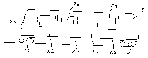
The coach body of a railway vehicle consists essentially of horizontal and
vertical panels (1, 2) with the horizontal panels (1) which form a floor as
well as a roof and the vertical panels, in particular the side panels
providing apertures (2a) which allow the installation of at least one window
and one access door. The horizontal and vertical panels (1, 2) are composed by
fibre reinforced split modules (3) with the joint running at right angle to
the longitudinal axis. Two of these modules (3) which are complementary and
juxtaposed are each time connected by a load-transmitting joint via their
horizontal panels (1) in the centre of the vehicle (4) thus forming a
longitudinal section of the coach body. The length of the coach body is made
up by the load-transmitting assembly of a number of the above mentioned
longitudinal sections by their abutment points (5) which extend at right angle
to the longitudinal axis of the vehicle.


French Abstract

Caisse de véhicule ferroviaire comprenant essentiellement des parois horizontales et des parois verticales (1, 2), dans laquelle les parois horizontales (1) forment le plancher et le toit, et les parois verticales, en particulier les parois formant les parois latérales (2), présentent des ouvertures (2a) permettant le montage d'au moins une fenêtre et d'une porte d'entrée. Les parois horizontales et verticales (1 et 2) sont formées par des modules (3) en matière plastique renforcée par des fibres, les moitiés de ces modules s'étendant, en coupe, perpendiculairement à l'axe longitudinal du véhicule. Ces modules (3), agencés deux par deux de façon complémentaire, sont assemblés de façon à assurer une transmission des forces, par leurs parois horizontales (1) se rencontrant dans la zone médiane (4) du véhicule et constituent une section longitudinale de la caisse. La longueur de la caisse résulte, en conséquence, de l'assemblage, assurant une transmission des forces, d'une pluralité des sections longitudinales précitées, à leurs points de butée (5) s'étendant perpendiculairement à l'axe longitudinal du véhicule.

Claims

Note: Claims are shown in the official language in which they were submitted.


CLAIMS
1. A coach body of a rail vehicle, comprising horizontal and
vertical walls, said horizontal walls serving to form both a floor and a
ceiling,
while said vertical walls forming side walls, said vertical walls having
cutouts
for at least one window and one boarding door, said horizontal and vertical
walls being formed by half-modules of fiber-reinforced plastic divided
sectionally crosswise to a longitudinal axis of the coach body, each two of
these half-modules which are complimentary to one another and are joined
in a force-transmitting way at said horizontal walls which meet in a middle of
the vehicle forming one longitudinal section of the coach body, and a length
of the coach body being formed accordingly by a force-transmitting
connection of a number of said longitudinal sections at abutting points at
which said longitudinal section abut against one another and which extend
all the way around in transverse direction of the vehicle, said longitudinal
sections including two longitudinal sections which extend all the way around
in a transverse direction of the coach body and have an abutting point
formed for securing accessory parts of the vehicle selected from the group
consisting of a partition, a passenger seat, and a support pole.
2. A coach body as defined in claim 1, wherein said half-
modules have four types, including one solid-surface module, one module

with a window cutout, one module with a door cutout, and one module as a
transition to a joint of a train combination.
3. A coach body as defined in claim 1, wherein said half-
modules include an inner layer, an outer layer and a core layer located
between said inner and outer layers for thermal and acoustic insulation, said
inner layer and said outer layer being composed of fiber-reinforced plastic.
4. A coach body as defined in claim 3, wherein said fiber-
reinforced plastic has a matrix material selected from the group consisting
of epoxy resins, unsaturated polyester resins, vinyl ester resins, and vinyl
resins.
5. A coach body as defined in claim 3, wherein said fiber-
reinforced plastic has fibers selected from the group consisting of glass
fibers, carbon fibers, aramide fibers, and natural fibers.
6. A coach body as defined in claim 1, wherein said half-
modules are formed as injection molded elements.
7. A coach body as defined in claim 1, wherein each of said
half-modules in its region to be joined in force-transmitting fashion to other
modules is formed so as to allow a joining technique with the use of joining

elements selected from the group consisting of screws, rivets, and
adhesives.
8. A coach body as defined in claim 1, wherein two of said
longitudinal sections extend all the way around in a transverse direction of
the coach body and have an abutting point lined with a strip.
9. A coach body as defined in claim 1, wherein said half-
modules are provided with ducts for receiving supply lines formed as cables.
10. A coach body of a rail vehicle, comprising horizontal and
vertical walls, said horizontal walls serving to form both a floor and a
ceiling,
while said vertical walls forming side walls, said vertical walls having
cutouts
for at least one window and one boarding door, said horizontal and vertical
walls being formed by half-modules of fiber-reinforced plastic divided
sectionally crosswise to a longitudinal axis of the coach body, each two of
these half-modules which are complimentary to one another and are joined
in a force-transmitting way at said horizontal walls which meet in a middle of
the vehicle forming one longitudinal section of the coach body, and a length
of the coach body being formed accordingly by a force-transmitting
connection of a number of said longitudinal sections at abutting points
extending all the way around in transverse direction of the vehicle, said half-
modules in a region of said horizontal walls on said ceiling and/or on said

floor having rectangular formations selected from the group consisting of
voids and grooves, and each receiving a belt which extends continuously
over a length of the coach body, said belt being stressable by tensile,
compressive and bending forces.
11. A coach body as defined in claim 10, wherein said belt has
fiber-reinforced plastic with longitudinally oriented endless fibers.

Description

Note: Descriptions are shown in the official language in which they were submitted.


CA 02253308 1998-10-27
FILE, ~ ' ~I'.~ i /1P~~-!is,:
~F=-~ a .'.lr~ ~I_n i n ~r~
St~ecification
Coach Body of Railway Vehicle
The invention relates to a coach body of a rail
vehicle, which substantially comprises horizontal and
vertical walls, wherein the horizontal walls serve to form
both a floor and a ceiling and the vertical walls, in
particular forming side walls, include cutouts that allow at
least one window and one boarding door to be installed.
In rail vehicles, it is well known to embody the
horizontal and vertical walls of the coach body by welded
steel construction, using rolled, square and hollow steel
sections with sheet metal welded directly onto such a
skeleton. Depending on its design, such as the number and
arrangement of windows and boarding doors, such a coach body
is as a rule suitably for only one particular application.
Any changes in this design, for instance by a different
placement of the boarding doors, means a new static concept
and often requires extensive structural adaptations. The
aforementioned steel construction of a coach body is also
complicated in terms of production and unfavorable from the
standpoint of having relatively high vehicle mass.
German Patent Disclosure DE-B 1 158 541 also discloses
a coach body of a rail vehicle in the prior art that
substantially comprises horizontal and vertical walls. The
horizontal walls serve to form both a floor and a ceiling.
The vertical walls, which in particular form side walls,
contain cutouts that allow windows and boarding doors to be
installed. The horizontal and vertical walls are formed by
half-modules of fiber-reinforced plastic divided sectionally
crosswise to the longitudinal axis of the vehicle: each of
1 AMENDED PAGE

"° CA 02253308 2001-08-09
22386-2667
these modules has a structural length equivalent to the
length of the coach body. As a result, very large equipment
is needed for manufacturing them (see Fig. 13 of DE-B 1 158
541) .
The object of the invention is to embody a coach
body of this generic type with a view to the simplest
possible economical production and a reduction in vehicle
mass, in which the coach body should en<~ble a high degree of
flexibility in designing the rail vehic:Le.
According to the invention, this object is
attained in that the horizontal and veridical walls are
formed by half-modules of fiber-reinforced plastic divided
sectionally crosswise to the longitudinal axis of the
vehicle, where two of these half module's, which are
complementary to one another and are joined in a force-
transmitting way at their horizontal wa7_ls that meet in the
vehicle middle, form one longitudinal sE:ction of the coach
body, and the length of the coach body c:an be designed
accordingly by force-transmitting connection of a number of
aforementioned longitudinal sections at their abutting
points extending all the way around in the transverse
direction of the vehicle.
Advantageous features of the invention are recited
in the dependent claims.
The advantages attainable with the subject of the
invention are in particular as follows:
The half-modules allow great flexibility in
vehicle design, because any desired configuration of a coach
body in its longitudinal and transverse directions can be
realized. The relatively short half-modules of fiber-
reinforced plastic can be produced simpl~~ and economically,
2

i
CA 02253308 2001-08-09
t
22386-2667
and compact, easily manipulated devices can be employed for
their production. Lower production costs for the coach body
are also attained because there is no need to line the
inside of the modules and to treat the outer surfaces for
applying a flat coating over a large area. A reduction in
the vehicle mass is also favorable, because energy costs for
transportation can then be saved. The modules of fiber-
reinforced plastic are free from corrosion and can thus be
used without maintenance.
The invention will be described in further detail
below in terms of an exemplary embodiment shown in principle
in the drawing. Shown are:
Fig. 1, a rail vehicle with a coach body according
to the invention in a side view;
Fig. 2, a portion of the coach body according to
the invention in a perspective view;
2a

CA 02253308 1998-10-27
WP 97/43158 PCT/DE 97/00930
Fig. 3, the section taken along the line A-A of Fig. 2:
Fig. 4, the section taken along the line B-B of Fig. 2;
Fig. 5, an alternative design, in section similar to
that of Fig. 3.
In Figs. 1 and 2, the coach body, supported on driven
or nondriven trucks 10, is put together from relatively short
half-modules 3, each of them comprising fiber-reinforced
plastic. Both the floor and the ceiling of the coach body
are formed by horizontal walls 1, and the side walls are
formed by vertical walls 2 of these modules 3. Two of these
complementary half-modules 3, joined together in force-
transmitting fashion at their horizontal walls 1 that meet in
the transverse center 4 of the vehicle, represent one
longitudinal section of the coach body. The length of the
coach body is obtained by force-transmitting joining together
of a suitable number of the aforementioned longitudinal
sections along their abutting points 5 extending all the way
around in the transverse direction of the vehicle.
The vertical walls 2 include cutouts 2a, which allow a
window - for instance in the form of a pane of glass 8
inserted as in Fig. 4 - or a boarding door to be installed.
The cutout 2a in the vertical wall 2 for installing a
boarding door may be supplemented with a recess (not shown)
inside the horizontal wall 1, so as to accommodate a set of
steps there. Aside from the above-described window modules
3.2 and door modules 3.3, solid-surface modules 3.1 and a
module 3.4 as a transition to a joint of a train connection
can selectively be used. The possibility also exists of
replacing a top part 9, shown in Fig. 1, which may also be
formed of fiber-reinforced plastic, with a further
articulated module 3.4, or conversely to replace the
articulated module 3.4 with a second top module 9. With the
3

CA 02253308 1998-10-27
WP 97/43158 PCT/DE 97/00930
aid of the above-described modules 3.1-3.4, any desired
configuration of a coach body in the longitudinal direction
and in the transverse direction can be readily realized for
instance, one long side of the coach body may have only
window modules 3.2, while the opposite long side includes two
door modules 3.3 combined with window modules 3.2.
In the present exemplary embodiment, the modules 3 have
rectangular voids 3d in the region of the horizontal walls 1
of the ceiling. In the region of the horizontal walls 1 of
the floor, the modules 3 are provided with corresponding
grooves 3e. The voids 3d and the grooves 3e each receive one
belt 7 extending continuously the length of the coach body,
and this belt can be acted upon by both tensile and
compressive forces and by bending forces. The belt 7 may be
a metal profile section or preferably may comprise fiber-
reinforced plastic with longitudinally oriented endless
fibers and can be produced for instance by pultrusion. In
terms of the static makeup of the coach body, there is a
separation between tensile and compressive loads, on the one
hand, which are transmitted with the aid of the continuous
belts 7, and thrust loads on the other, whose transmission is
effected through the modules 3.
As Figs. 3-5 show, the modules 3 are formed of an inner
layer 3a of fiber-reinforced plastic, an outer layer 3b of
the same material, and a core layer 3, disposed between these
layers, with good properties in terms of thermal and acoustic
insulation. Various lightweight construction materials are
suitable for the core layer 3c, such as balsa wood, foam
materials, and honeycomb materials. The fiber-reinforced
plastic has glass, carbon, aramide, and/or natural fibers.
As the reinforcing material, glass, carbon, aramide and/or
other reinforcing fibers can be used; the selection of the
4

CA 02253308 1998-10-27
WP 97/43158 PCT/DE 97/00930
fiber material can depend on the applicable local load on the
modules 3. It is understood that the fiber-reinforced
plastic will meet the relevant fireproofing regulations. For
the production of the modules 3, injection molding is
recommended, because with it finished surfaces that are
smooth on the inside and outside can be attained. Thus the
usual lining of the inside and painting flat coatings over
large areas of the outer surfaces before final painting as in
metal coach bodies, are accordingly unnecessary.
Each half-module, in its region to be joined in force-
transmitting fashion to other modules, is embodied to suit
the joining technique that employs screws, rivets and/or
adhesive bonding. To that end, as shown in Figs. 3-5, the
inner layer 3a and the outer layer 3b are put together; as
shown in Figs. 3 and 4, this forms an angle section 3f that
can be used for the joining using screws, rivets and adhesive
bonding. In Fig. 5, the joining is done solely by adhesive
bonding, using a reinforcing strip 3g.
The abutting point 5 of two longitudinal sections,
which extends all the way around crosswise of the vehicle,
can be lined by a strip 6, shown in Figs. 2-4, only a portion
of which is shown in Fig. 2. The abutting point 5 extending
all the way around crosswise of the vehicle can at the same
time, because of its stability, be utilized for securing
accessory parts of the vehicle, such as a partition,
passenger seat or support pole. The void, covered by the
strip 6, in the region of the abutting point 5 is suitable
for receiving supply lines, such as cables and pipes. The
half-modules 3 may also have ducts, not shown, for such
supply lines.
List of Reference Numerals

CA 02253308 1998-10-27
WP 97/43158 PCT/DE 97/00930
1 Horizontal wall
2 Vertical wall
2a Cutout for window or boarding door
3 Half-module of fiber-reinforced plastic
3.1 Solid-surface module
3.2 Module with window cutout (window module)
3.3 Module with door cutout (door module)
3.4 Module as transition to a joint of a train
connection (articulated module)
3a Inner layer
3b Outer layer
3c Core layer
3d Rectangular void
3e Rectangular groove
3f Angle section
3g Reinforcing strip
4 Transverse center of the vehicle
Abutting point, extending all the way around
crosswise of the vehicle
6 Strip
7 Belt
8 Pane of glass
9 Top part
Truck
6

Representative Drawing
A single figure which represents the drawing illustrating the invention.
Administrative Status

2024-08-01:As part of the Next Generation Patents (NGP) transition, the Canadian Patents Database (CPD) now contains a more detailed Event History, which replicates the Event Log of our new back-office solution.

Please note that "Inactive:" events refers to events no longer in use in our new back-office solution.

For a clearer understanding of the status of the application/patent presented on this page, the site Disclaimer , as well as the definitions for Patent , Event History , Maintenance Fee  and Payment History  should be consulted.

Event History

Description Date
Inactive: IPC from MCD 2006-03-12
Time Limit for Reversal Expired 2004-05-03
Letter Sent 2003-05-05
Grant by Issuance 2002-07-23
Inactive: Cover page published 2002-07-22
Inactive: Final fee received 2002-03-06
Pre-grant 2002-03-06
Notice of Allowance is Issued 2001-09-20
Letter Sent 2001-09-20
Notice of Allowance is Issued 2001-09-20
Letter Sent 2001-09-19
Inactive: Final fee received 2001-08-09
Reinstatement Requirements Deemed Compliant for All Abandonment Reasons 2001-08-09
Inactive: Adhoc Request Documented 2001-08-09
Inactive: Abandoned - No reply to Office letter 2001-05-22
Inactive: Office letter 2001-02-19
Inactive: Approved for allowance (AFA) 2001-02-08
Amendment Received - Voluntary Amendment 2000-12-14
Inactive: S.30(2) Rules - Examiner requisition 2000-09-11
Letter Sent 2000-06-13
Inactive: Multiple transfers 2000-01-20
Inactive: RFE acknowledged - Prior art enquiry 1999-03-11
All Requirements for Examination Determined Compliant 1999-02-16
Request for Examination Requirements Determined Compliant 1999-02-16
Request for Examination Received 1999-02-16
Inactive: IPC assigned 1999-01-14
Classification Modified 1999-01-14
Inactive: First IPC assigned 1999-01-14
Inactive: Notice - National entry - No RFE 1998-12-23
Application Received - PCT 1998-12-21
Application Published (Open to Public Inspection) 1997-11-20

Abandonment History

There is no abandonment history.

Maintenance Fee

The last payment was received on 2002-05-03

Note : If the full payment has not been received on or before the date indicated, a further fee may be required which may be one of the following

  • the reinstatement fee;
  • the late payment fee; or
  • additional fee to reverse deemed expiry.

Patent fees are adjusted on the 1st of January every year. The amounts above are the current amounts if received by December 31 of the current year.
Please refer to the CIPO Patent Fees web page to see all current fee amounts.

Owners on Record

Note: Records showing the ownership history in alphabetical order.

Current Owners on Record
SIEMENS DUEWAG SCHIENENFAHRZEUGE GMBH
Past Owners on Record
DIETER MUHLHAHN
KARL-JOSEF SCHRODER
MATTHIAS KOEPPE
Past Owners that do not appear in the "Owners on Record" listing will appear in other documentation within the application.
Documents

To view selected files, please enter reCAPTCHA code :


To view images, click a link in the Document Description column. To download the documents, select one or more checkboxes in the first column and then click the "Download Selected in PDF format (Zip Archive)" or the "Download Selected as Single PDF" button.

List of published and non-published patent-specific documents on the CPD .

If you have any difficulty accessing content, you can call the Client Service Centre at 1-866-997-1936 or send them an e-mail at CIPO Client Service Centre.


Document
Description 
Date
(yyyy-mm-dd) 
Number of pages   Size of Image (KB) 
Abstract 1998-10-26 1 63
Description 1998-10-26 8 318
Claims 1998-10-26 4 133
Drawings 1998-10-26 2 50
Claims 2000-12-13 4 112
Representative drawing 2002-06-17 1 6
Representative drawing 1999-01-24 1 8
Description 2001-08-08 7 282
Reminder of maintenance fee due 1999-01-04 1 110
Notice of National Entry 1998-12-22 1 192
Courtesy - Certificate of registration (related document(s)) 1998-12-22 1 115
Acknowledgement of Request for Examination 1999-03-10 1 173
Courtesy - Abandonment Letter (Office letter) 2001-07-02 1 171
Notice of Reinstatement 2001-09-18 1 176
Commissioner's Notice - Application Found Allowable 2001-09-19 1 166
Maintenance Fee Notice 2003-06-01 1 172
Correspondence 2002-03-05 1 46
PCT 1998-11-04 6 209
Fees 2002-05-02 1 38
Correspondence 2000-02-16 1 11
Correspondence 2001-02-18 1 21