Language selection

Search

Patent 2253522 Summary

Third-party information liability

Some of the information on this Web page has been provided by external sources. The Government of Canada is not responsible for the accuracy, reliability or currency of the information supplied by external sources. Users wishing to rely upon this information should consult directly with the source of the information. Content provided by external sources is not subject to official languages, privacy and accessibility requirements.

Claims and Abstract availability

Any discrepancies in the text and image of the Claims and Abstract are due to differing posting times. Text of the Claims and Abstract are posted:

  • At the time the application is open to public inspection;
  • At the time of issue of the patent (grant).
(12) Patent Application: (11) CA 2253522
(54) English Title: SCANNER-LENS-FRAME
(54) French Title: LECTEUR OPTIQUE - LENTILLE - CADRE
Status: Deemed Abandoned and Beyond the Period of Reinstatement - Pending Response to Notice of Disregarded Communication
Bibliographic Data
(51) International Patent Classification (IPC):
  • G03G 21/00 (2006.01)
  • G03G 15/00 (2006.01)
  • H04N 01/04 (2006.01)
  • H04N 01/10 (2006.01)
(72) Inventors :
  • HYMAN, MILES ANTHONY (Canada)
(73) Owners :
  • MILES ANTHONY HYMAN
(71) Applicants :
  • MILES ANTHONY HYMAN (Canada)
(74) Agent: SMART & BIGGAR LP
(74) Associate agent:
(45) Issued:
(22) Filed Date: 1998-11-09
(41) Open to Public Inspection: 2000-05-09
Examination requested: 1998-11-09
Availability of licence: N/A
Dedicated to the Public: N/A
(25) Language of filing: English

Patent Cooperation Treaty (PCT): No

(30) Application Priority Data: None

Abstracts

English Abstract


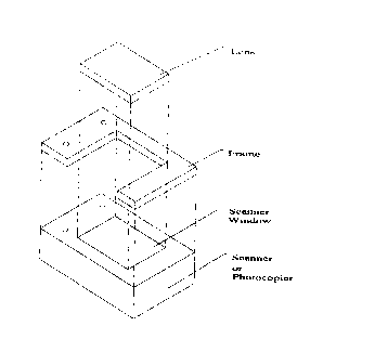
An accessory for flat bed scanners and photocopiers is provided. The accessory
allows pages from bound books, especially in the binding region to be scanned
or copied.
The accessory may comprise either a frame together with a lens, or a lens
alone. The
frame may be of varying geometrical shapes with a lens within the frame, and
with the lens
having one straight edge that may or may not be framed by a narrow frame or an
angled
frame. The frame and lens, or the lens alone sit on the top of the scanning or
photocopying
surface of the scanner or photocopier. In use, the spine of the book is placed
so that it
coincides with the unframed edge of the lens.


Claims

Note: Claims are shown in the official language in which they were submitted.


Page 6
CLAIMS
1. An attachment or accessory to flat bed scanners and photocopiers
comprising a rectangular frame housing a lens, whereby the frame borders
three sides of the lens with one side of the lens being free of a frame.
2. An attachment or accessory to flat bed scanners and photocopiers
comprising a rectangular frame housing a lens, whereby the frame borders
four sides of the lens with one side of the lens having a narrow frame.
3. An attachment or accessory to flat bed scanners and photocopiers
comprising a rectangular frame housing a lens, whereby the frame borders
four sides of the lens with the frame on the fourth side of the lens being
angled.
4. An attachment or accessory to flat bed scanners and photocopiers
comprising a frame of varying shapes housing a lens, whereby the frame
borders all sides of the lens, with one side of the lens having either a
straight
narrow frame or a straight angled frame.
5. An attachment or accessory to flat bed scanners and photocopiers
comprising a frame of varying shapes housing a lens, whereby the frame
borders all but one side of the lens, with the side of the lens not bordered
by
a frame, having a straight edge.
6. An attachment or accessory to flat bed scanners and photocopiers,
comprising a frame and lens, as defined in claims 1, 2 3, 4 and 5 in which
the frame is made of wood, metal, plastic, composite material or a composite
of materials.
7. An attachment or accessory to flat bed scanners and photocopiers,
comprising a frame and lens, as defined in claims 1, 2, 3, 4 and 5 in which
the dimensions, and shape of the frame will vary and change to
accommodate different models or makes of flat bed scanners and
photocopiers.
8. An attachment or accessory to flat bed scanners and photocopiers,
comprising a frame and lens, as defined in claims 1, 2, 3, 4 and 5, in which
the frame provides attachment points to affix the attachment or accessory to
flat bed scanner and photocopiers, as defined in claims 1, 2 3, 4 and 5 to the
flat bed scanner or photocopier and to reaffix the flat bed scanner or
photocopier's cover to the frame.

Page 7
9. An attachment or accessory to flat bed scanners and photocopiers,
comprising a frame and lens, as defined in claims 1, 2, 3, 4 and 5 in which
the frame provides no attachment points to affix either the attachment or
accessory to flat bed scanner and photocopiers, as defined in claims 1, 2, 3,
4 and 5 to the flat bed scanner or photocopier; or to reaffix the flat bed
scanner or photocopier's cover to the frame.
10. An attachment or accessory to flat bed scanners and photocopiers
comprising a lens of varying geometrical shapes with attachment devices that
enable the lens to be fixed to the surface of a flat bed scanner or
photocopier,
and the cover of the flat bed scanner or photocopier to be re-affixed to the
lens.
11. An attachment or accessory to flat bed scanners and photocopiers
comprising a frame and lens, or a lens with attachment devices as defined in
claims 1, 2, 3, 4, 5 and 10 in which the lens may be solid, hollow or a
lamination of materials.
12. An attachment or accessory to flat bed scanners and photocopiers
comprising a frame and lens, or a lens with attachment devices as defined in
claims 1, 2, 3, 4, 5 and 10 in which the surfaces of the lens may be of a
varied or differing grain or texture.
13. An attachment or accessory to flat bed scanners and photocopiers
comprising a frame and lens, or a lens with attachment devices as defined in
claims 1, 2, 3, 4, 5 and 10 in which the lens may be made out of plastic,
treated plastic, glass, or a composite of materials.
14. An attachment or accessory to flat bed scanners and photocopiers
comprising a frame and lens, or lens with attachment devices as defined in
claims 1, 2, 3, 4, 5 and 10 in which the lens may be so constructed as to fit
the entire window of the flat bed scanner or photocopier or any portion of the
window of the scanner or photocopier.
15. An attachment or accessory to flat bed scanners and photocopiers
comprising a frame and lens, or a lens with attachment devices as defined in
claims 1, 2, 3, 4, 5 and 10 in which the lens may be optically clear or
tinted.
16. An attachment or accessory to flat bed scanners and photocopiers
comprising a frame and lens, or a lens with attachment devices as defined in
claims 1, 2, 3, 4, 5 and 10 in which the lens may be tailored to pass only
certain spectrums of light or may admit polychromatic light frequencies.

17. An attachment or accessory to flat bed scanners and photocopiers
comprising a frame and lens, or a lens with attachment devices as defined in
claims 1, 2, 3, 4, 5 and 10 in which the lens may be polarized or non
polarized.
18. An attachment or accessory to flat bed scanners and photocopiers
comprising a frame and lens, or a lens with attachment devices as defined in
claims 1, 2, 3, 4, 5 and 10 in which the lens may be of varied density and
thickness.
19. An attachment or accessory to flat bed scanners and photocopiers
comprising a frame and lens, or a lens with attachment devices as defined in
claims 1, 2, 3, 4, 5 and 10 in which the lens has varying focal points.
20. An attachment or accessory to flat bed scanners and photocopiers
comprising a frame and lens, or a lens with attachment devices as defined in
claims 1, 2, 3, 4, 5 and 10 in which the lens gives rise to varying focal
lengths.

Description

Note: Descriptions are shown in the official language in which they were submitted.


CA 02253522 1998-11-09
Page 1
1 BACKGROUND OF THE INVENTION
The present invention generally relates to improvements in the scanning and
photocopying of bound documents in portrait mode.
The current design of flat bed scanners and photocopiers makes it difficult to
scan or
photocopy bound documents in portrait mode. Currently, when a person desires
to
scan or photocopy bound documents such as text books, in portrait mode, a
heavy
downward pressure is required to force the pages of the bound materials onto
the
scanner or photocopier window. This downward pressure is needed so that the
print
that is close to the binding region of the material, can be brought within the
optical
field of view of the scanner or photocopier. This increases the wear and tear
of
scanners and photocopiers and decreases the life span of the scanners or
photocopiers. The heavy downward pressure that is exerted on bound materials,
increases the stress on such materials, and decreases the longevity of such
materials.
The present invention is a frame and lens attachmentlaccessory to flat bed
scanners
and photocopiers, or a lens only attachment/accessory to flat bed scanners and
photocopiers. The present invention eliminates the need to place the heavy
downward pressure, on bound materials, that is required to force the bound
materials onto the scanner or photocopier window.
The frame is an optional component of the present invention. The frame, where
used, may have attachment points that enable it to be fixed to the top of the
scanner
or copier. Where there is no frame and only a lens is used, the lens may have
attachment devices that will enable it to be fixed firmly to the top of a flat
bed
scanner or photocopier.
The present invention will make it possible for a user to use a relatively
inexpensive
scanner or photocopier to easily scan small and large bound materials into the
binding region of the bound materials. The materials that are scanned may be
transparent or reflective. As well, the present invention will make it
possible to scan
or photocopy single sheet or spooled materials.
The present invention also makes possible a quick repositioning of the bound
material without the need to reposition the scanner or photocopier's field of
recognition. Because the present invention is an attachment to existing
scanners
and photocopiers, as opposed to a modification of scanners and photocopiers,
it can
35. be moved from scanner to scanner, from scanner to photocopier and from
photocopier to photocopier as appropriate. The attachment nature of the
present
invention also means that it can still be used when the owner of the scanner
or
photocopier upgrades to another scanner or photocopier.

CA 02253522 1998-11-09
Page 2
SUMMARY OF INVENTION
40 It is a principal object of the present invention to provide an attachment
or accessory
for flat bed scanners and photocopiers that permits the scanning and
photocopying
of bound materials in portrait mode without the need to exert a heavy downward
pressure to force the bound material to be scanned or photocopied onto the
window
of the scanner or photocopier.
45 Still another object of the invention is to provide an attachment or
accessory for flat
bed scanners and photocopiers that permits the easy scanning or photocopying
of
bound printed materials into the binding region of the printed material
A further object of the present invention is to permit bound material to be
easily
positioned parallel to the scan window of flat bed scanners and photocopiers.
50 The above and other objects of the present invention will become apparent
from a
reading of the following description taken in conjunction with the
accompanying
drawings which illustrate the preferred embodiments thereof.
BRIEF DESCRIPTION OF THE DRAWINGS
The present invention is illustrated by the attached drawings.
55. Figure 1: is a drawing of the optional frame component of the
present invention that houses the lens of the present invention. The
frame is shown with attachment points, shown as circles on left side of
the frame. The attachment points enable the frame to be attached to a
flat bed scanner or photocopier, and also enable the cover of a
scanner or photocopier to be affixed to the frame.
61. Figure 2: is a two dimensional drawing of the structure of the
present invention. The frame as shown in Figure 1, is shown in this
illustration as housing a lens. The whole invention is shown as fixed to
a scanner or photocopier by means of the attachment points. In this
illustration, the frame is shown with its end or edge extending beyond
the lens, and not enclosing the lens. The top edges of the parts of the
frame that do not enclose the lens are the Locating points B, one of
which is labeled in Figure 4.
68 Instead of being enclosed or housed in a frame, as shown in this
illustration, the lens may stand alone, but may have a variety of

CA 02253522 1998-11-09
Page 3
attachment devices that enable it to be fixed to the top of the flat bed
scanner or photocopier without the need for the frame.
72. Figure 3: is a three dimensional view of the structure of the
present invention, when it is placed on top of a scanner or
photocopier. The illustration shows the separate components of the
present invention.
76. Figure 4: is a drawing of the present invention showing the
location points when a book is placed on the present invention.
Locating point A, is the top edge or side of the lens that comes into
contact with the meeting point, in the binding region of a book or other
bound material, between adjacent pages. Locating point A allows the
binding region of the bound material to come into the optical field of
view, or scan region of the scanner or photocopier. In this illustration,
Locating point B is the top end of one of the parts of the frame that
extends beyond the edge of the lens and does not enclose any part of
the lens. Locating point B makes possible the accurate positioning
and repositioning of the printed material within the scanner or
photocopier's optical field of view. Locating point B also prevents the
bound material from slipping to either the left or the right of the
scanner of photocopier. In this illustration, the invention itself is shown
resting on a flat bed scanner or photocopier.
DESCRIPTION OF THE PREFERRED EMBODIMENTS
92. Referring to the drawings, specifically Figures 1 to 4, which illustrate
the
present invention:
94. Figure 1 is a drawing of the frame that houses the lens of the present
invention. The purpose of the frame is to provide attachment points by means
of which the present invention may be fixed to the surface of the scanner or
photocopier.
99. In the illustration, the frame is shown with attachment points, shown as
circles on one of the sides of the frame. The attachment points enable the
frame to be attached to a flat bed scanner or photocopier, and also enable
the cover of a scanner or photocopier to be affixed to the frame. The frame is
optional.
104 Instead of a frame as shown in this illustration, the lens may be held in
position on the surface of the scanner or photocopier by a variety of
attachment devices. Where a frame is employed, the dimensions of the frame

CA 02253522 1998-11-09
Page 4
and its shape will vary and change to accommodate different models or
makes of scanners and photocopiers. The frame may be made of wood,
metal plastic, composite material or a composite of materials.
106 In this illustration, the frame is shown as being rectangular in shape,
with only three sides of the rectangle having a frame. One side is free of a
frame. The frame that houses the lens may also have four sides with a
narrow fourth side. The frame may also have three straight sides, and a
fourth angled side or edge.
111. The frame may also be of other varying geometrical shapes to
accommodate the shapes of the surtaces of various makes and models of
scanner and photocopiers. If a frame is employed, whatever its shape, one
side will be free of a frame, will have an angled frame, or will have a narrow
frame.
116 Figure 2 and Figure 3 are, respectively, a two and three dimensional
illustration of the present invention as it fits atop a flat bed scanner or
photocopier. Figures 2 and 3 show the frame, together with the lens, placed
atop a flat bed scanner or photocopier or fixed to the flat bed scanner or
photocopier by way of the attachment points.
121 The lens may be made of plastic, treated plastic, glass, or a composite
of materials. The lens may be solid, hollow or a lamination of materials. The
lens may be so constructed so as to fit the entire window of the scanner or
photocopier or any portion of the window of the scanner or photocopier. The
surfaces of the lens may be of a varied or differing grain or texture. The
lens
may be of varied density or thickness and may be of different shapes. The
lens may have positioning devices attached to it to accommodate various
media. The lens may also be optically clear or tinted. The lens may also be
tailored to pass only certain spectrums of light or may admit polychromatic
light frequencies. The lens may be polarized or non polarized.
Instead of being housed in a frame, the lens may have attachment devices
that enable it to be fixed firmly to the surface of the flat bed scanner or
photocopier.
134 Figure 4 is a drawing of the present invention showing the location
points of a bound material or text book, when it is placed on the present
invention. The invention itself is shown resting on a flat bed scanner or
photocopier. The frame of the present invention provides attachment points
to affix it to the flat bed scanner or photocopier and to reaffix the scanner
or
photocopier's cover to the frame. The top edges of the lens provides locating
points to allow the binding region of the bound printed material to be brought
into the optical field of view (the scan or copy region) of the scanner or
photocopier.
143 In this illustration, Locating point A, is the top edge or side of the
lens
that comes into contact with the meeting point, in the binding region of a
book
or other bound material, between adjacent pages. Locating point A allows the

CA 02253522 1998-11-09
Page 5
binding region of the bound material to come into the optical field of view,
or
scan region of the scanner or photocopier. In this illustration, Locating
point B
is the top edge of one of the ends of the frame that extends beyond the end
of the lens and does not enclose any part of the lens. Locating point B makes
possible the accurate positioning and repositioning of the printed material in
the scanner or photocopier's optical field of view. Locating point B also
prevents the bound material from slipping off to either the left or the right
of
the scanner of photocopier.
154 In use, in order to scan or photocopy bound material, the present
invention, with or without the frame, is fixed to the surface or window of the
scanner or photocopier. The bound material to be scanned or photocopied is
then placed on the surface of the present invention so that the page to be
copied is parallel to the scanner or photocopier window. The binding region
of the material is thus brought into contact with the top edge of the lens,
the
Locating point A. Where the optional frame component is used, the
remainder of the book or bound material is lodged between the two ends of
the frame that extend beyond the lens, Locating points B. Because the
binding region of the book comes into the optical field of view of the lens,
no
downward pressure is required to scan or photocopy the page concerned in
portrait mode. When one page is copied, the bound material may be quickly
and accurately repositioned so that the next page to be scanned or copied is
parallel to the scanner of photocopier's window. The cover of the scanner or
photocopier may be attached to the frame by the attachment points.

Representative Drawing
A single figure which represents the drawing illustrating the invention.
Administrative Status

2024-08-01:As part of the Next Generation Patents (NGP) transition, the Canadian Patents Database (CPD) now contains a more detailed Event History, which replicates the Event Log of our new back-office solution.

Please note that "Inactive:" events refers to events no longer in use in our new back-office solution.

For a clearer understanding of the status of the application/patent presented on this page, the site Disclaimer , as well as the definitions for Patent , Event History , Maintenance Fee  and Payment History  should be consulted.

Event History

Description Date
Inactive: IPC from MCD 2006-03-12
Application Not Reinstated by Deadline 2002-08-12
Inactive: Dead - No reply to s.30(2) Rules requisition 2002-08-12
Deemed Abandoned - Failure to Respond to Maintenance Fee Notice 2001-11-09
Inactive: Abandoned - No reply to s.30(2) Rules requisition 2001-08-13
Inactive: S.30(2) Rules - Examiner requisition 2001-04-12
Application Published (Open to Public Inspection) 2000-05-09
Inactive: Cover page published 2000-05-08
Inactive: First IPC assigned 1999-01-15
Inactive: IPC assigned 1999-01-15
Classification Modified 1999-01-14
Inactive: IPC assigned 1999-01-14
Application Received - Regular National 1998-12-21
Inactive: Filing certificate - RFE (English) 1998-12-21
Request for Examination Requirements Determined Compliant 1998-11-09
All Requirements for Examination Determined Compliant 1998-11-09

Abandonment History

Abandonment Date Reason Reinstatement Date
2001-11-09

Maintenance Fee

The last payment was received on 2000-11-07

Note : If the full payment has not been received on or before the date indicated, a further fee may be required which may be one of the following

  • the reinstatement fee;
  • the late payment fee; or
  • additional fee to reverse deemed expiry.

Patent fees are adjusted on the 1st of January every year. The amounts above are the current amounts if received by December 31 of the current year.
Please refer to the CIPO Patent Fees web page to see all current fee amounts.

Fee History

Fee Type Anniversary Year Due Date Paid Date
Request for examination - small 1998-11-09
Application fee - small 1998-11-09
MF (application, 2nd anniv.) - small 02 2000-11-09 2000-11-07
Owners on Record

Note: Records showing the ownership history in alphabetical order.

Current Owners on Record
MILES ANTHONY HYMAN
Past Owners on Record
None
Past Owners that do not appear in the "Owners on Record" listing will appear in other documentation within the application.
Documents

To view selected files, please enter reCAPTCHA code :


To view images, click a link in the Document Description column. To download the documents, select one or more checkboxes in the first column and then click the "Download Selected in PDF format (Zip Archive)" or the "Download Selected as Single PDF" button.

List of published and non-published patent-specific documents on the CPD .

If you have any difficulty accessing content, you can call the Client Service Centre at 1-866-997-1936 or send them an e-mail at CIPO Client Service Centre.


Document
Description 
Date
(yyyy-mm-dd) 
Number of pages   Size of Image (KB) 
Abstract 1998-11-08 1 19
Description 1998-11-08 5 290
Drawings 1998-11-08 4 36
Claims 1998-11-08 3 137
Representative drawing 2000-05-02 1 7
Filing Certificate (English) 1998-12-20 1 163
Reminder of maintenance fee due 2000-07-10 1 109
Courtesy - Abandonment Letter (Maintenance Fee) 2001-12-09 1 183
Courtesy - Abandonment Letter (R30(2)) 2001-10-21 1 171
Fees 2000-11-06 1 46