Note: Descriptions are shown in the official language in which they were submitted.
CA 022~3727 1998-10-28
W O 98/38047 PCT/CA98/00164 --
STORAGE UNIT AND ~HF.I.F CONSTRUCTION THli.RFFOR
FIELD OF THE INVENTION
The present invention relates to storage units and shelf constructions for storage
units. It is considered particularly suitable for but not limited to the storage of telephone
s directories, catalogs or other similar reference materials which are relatively thick, heavy and
soft bound, and which may be referred to on frequent occasions.
BACKGROUND TO THE INVENTION
There are a variety of known storage units or stands which are used or which may
be used for the purpose of storing soft bound reference materials such as telephone
o directories, catalogs or other similar publications. These range from basic bookcase
constructions to various stacked tray constructions. Many storage units are free standing
and some of these are designed to be positioned on top of a desk, counter or the like. Some
storage units are built in units (e.g. into a wall, or into a desk). However, the available
constructions are generally not well suited for the purpose of storing soft bound
5 publications, particularly in those cases where the publication is relatively thick and heavy
and there is a need to store and retrieve the publication on frequent occasions.
Telephone directories l~plesent a good example of larger soft bound publications
which may be referred to on frequent occasions. Depending upon the region covered by a
dir~cto.~y, its thickness may readily exceed two or, in some cases, three inches. As such, it
20 cannot readily stand upright on a storage shelf. Without the inconvenience of bracing the
directory each time it is inserted back on the shelf, it will simply collapse or slip under its
own weight. The tendency to do so will often worsen with repeated usage because the
directory pages will tend to lose their overall compactness.
Consequently, telephone directories will often be laid flat on a storage shelf.
25 However, this can present an awkward situation when there is a subsequent need to remove
CA 022~3727 1998-10-28
W O 98/38047 PCTtCA98/00164 -
the directory from the shelf. Unless the directory is left protruding from the shelf (which is
itself undesirable), it can be difficult to quickly place a firm grip on the directory at a later
time. More particularly, it can be difficultfor a user to engage the thickness of the directory
between his or her thumb and the full extent of his or her fingers. Typically, the user may
s try to slide, or to lift and slide the directory using the thumb and finger tips. But, this
requires a measurable amount of strength at the finger tips - strength which may be limited
or lacking in some people, and strength which others may prefer not to exert if they had a
choice. Further, the use of one's finger tips to move or lift such a directory creates a risk of
fingernail damage.
0 On other occasions telephone directories may simply be stacked in the open, one on
top of the other, and a telephone desk set will sometimes be rested on top of the stack.
However, while the resulting collection occupies minimum volume, it is a nuisance to move
one object to retrieve another. Further, the situation invites disorgAni7~tion and clutter
following the use of a directory unless the collection is carefully restacked.
Accordingly, a primary object of the present invention is to provide a new and
improved storage unit with a construction which permits an object such as a telephone
directory to be stored for easy retrieval by an average adult user.
A further object of the present invention is to provide a new and improved storage
unit with a construction which enables an average adult user to easily place a firm grip on a
stored object such as a telephone dil G~tOI ,y which is stored in a flat position in the unit.
Yet another object of the present invention is to provide a new and improved storage
unit which may be adapted to store two or more objects such as telephone directories, both
in an organized manner and in a manner which permits easy retrieval by an average adult
user.
CA 022~3727 1998-10-28
W O 98/38047 PCT/CA98/00164 -
SUMMARY OF THE INVENTION
In accordance with a broad aspect of the present invention there is provided a storage
unit comprising a shelf and means for supporting the shelf in a horizontal position for
storing objects on the shelf. The shelf may be an elevated shelf or it may be formed from
5 the base of the storage unit. In either case, the shelf includes a front edge with a rearwardly
extending recess, the recess being sized to permit substantially the entire length of the flatly
extended fingers of an average adult user's hand to reach into the recess for grasping an
object stored on the shelf and overlying the recess.
To enable the foregoing reach, the recess preferably has a width of about 3.5 inches
0 or greater and a rearward depth of about 3 inches or greater. The thickness will obviously
depend upon the thickness of the shelf but, in a preferred embodiment where a base which
provides vertical support for the storage unit also provides the shelf space, the base
thickness and consequently the recess thickness is preferably about 3/4 inches or greater. If
the bottom of the base rests on a floor, desk, or other such surface, this thickness will
15 accommodate the thickness of the user's fingers and permit the fingers to extend above the
surface and beneath the object stored on the base.
In a preferred embodiment, the storage unit is in the form of a sectional storage unit
which comprises a lower storage section and an upper storage section stackable on the lower
section. Each section includes opposed side walls and a rear wall extending between the
20 side walls. The sectional unit further includes a shelf and means for supporting the shelf in
a horizontal position engaged between the upper and lower sections to provide a top for the
lower section and a bottom for the upper section. The lower section includes means for
slidingly en~ging the upper section when stacked on the lower section, and the shelf
includes a rearwardly extending recess as described above in its front edge.
2s Advantageously, the lower section includes a base extending between the side walls
of the section for providing vertical support for the unit, the base including a horizontal
CA 022~3727 1998-10-28
W O 98/38047 PCT/CA98/00164 -
upper surface for storing objects on the surface and a front edge with a rearwardly extending
recess as described above. When the unit includes both a recessed base and a recessed
shelf, then the sectional unit may be readily adapted to conveniently organize and store a pair
of sirnilar or related publications within an easy to reach, vertically compact, space. For
5 example, the publications could be a pair of telephone directories, or they could be a
telephone directory and a Yellow PagesTM advertising directory, the height of each storage
section being slightly greaterthan the thickness of the corresponding publication.
To further advantage the upper storage section may include means for slidingly
eng~ging a further upper storage section stacked on the first upper storage section. With the
0 further upper storage section similarly structured, the overall storage unit may be
conveniently assembled with as many upper storage sections as are required to accolllnlodate
the number of publications or other objects to be stored.
The foregoing and other features and advantages of the present invention will now
be described with reference tCJ the drawings.
15 BRIEF DESCRIPTION OF THE DRAWINGS
Fig. 1 is an orthographic view of a sectional storage unit in accordance with the
present invention.
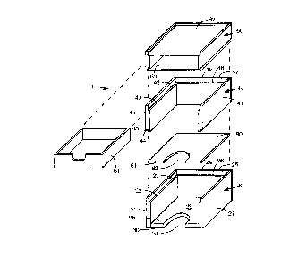
Fig. 2 is an exploded o~thographic view of the storage unit shown in Fig. 1.
Fig. 3 is a front elevation view of the rear wall in a lower storage section of the
20 storage unit shown in Fig. 1.
Fig. 4isanendelevationviewoftherearwallshown inFig. 3.
Fig. 5 is a front elevation view of a side wall in a lower storage section of the
storage unit shown in Fig. 1.
Fig. 6 is an end elevation view of the side wall shown in Fig. 5.
CA 022~3727 1998-10-28
W 098/38047 PCT/C~98/00164 -
Fig. 7 is a front elevation view of the rear wall in an upper storage section of the
storage unit shown in Fig. I .
Fig. 8 is an end elevation view of the rear wall shown in Fig. 7.
Fig. 9 is a front elevation view of a side wall in an upper storage section of the
S storageunitshowninFig. l.
Fig. 10 is an end elevation view of the side wall shown in Fig. 9.
Fig. 11 is an isometric view illustrating the use of storage shown in Fig. I .
DETAILED DESCRlPTIQN OF PREFF.RRF.I) EMBODIMENI
The storage unit generally designated l0 which is illustrated in Figs. 1 to 11 is one
0 which is considered particularly suitable for the storage and easy retrieval of publications
such as telephone directories. lt is a sectional storage unit which includes a lower storage
section generally designated 20, a first upper storage section generally design~ted 40, and a
second upper storage or drawer section generally designated 60. Storage unit 1 further
includes a shelf 80 which, when the unit is assembled, provides a top for lower section 20
lS and a bottom for upper section 40.
Lower section 20 is formed from a pair of opposed side walls 21 and a rear wall 24
which extends between the side walls. Each side wall 21 includes an inwardly facing
dovetail 22 along its top edge with an i~mer upwardly facing horizontal ledge 23. Similarly,
rear wall 24 includes an inwardly facing dovetail 25 along its top edge with an inner
upwardly facing horizontal ledge 26. Ledges 23, 26 of dovetails 22, 25 provide a means for
supporting shelf 80 in a horizontal position. Further, as is described below in more detail,
dovetails 22, 25 provide a means for slidingly engaging col-c~ol1ding dovetails along the
lower edges of upper section 40.
CA 022~3727 1998-10-28
W O 98/38047 PCT/CA98/00164
A base 28 extends between the side walls 21 of lower section 20 and contributes to
overall vertical support for storage unit 1. Base 28 includes a horizontal upper surface 29
for storing objects on the surface and a front edge 30 with a rearwardly extending recess 3 1.
For the purpose of holding a telephone directory such as directory 100 depicted in
s Fig. 11, the storage space provided by lower section 20 is preferably sized to receive the
directory lengthwise. Typically, the interior width between side walls 21 may be about 11
inches thereby serving to guide and m~in~in a lengthwise orientation as the di.e~tc 1 y is
moved into the space. The interior depth from the most forward part of front edge 30 to rear
wall 24 may be about 12 inches thereby serving to stop the directory if it is moved beyond a
I o position where its edge is flush with the forward part of edge 30. If the hei ght from upper
surface 29 to the level of ledges 23, 26 is set at about 4 inches, then the available space
within section 20 will be a compact space suitable for most if not all North American
telephone directories. Concurrently, it will allow a vertical clearance space 101 between
directory 100 and the bottom of shelf 80.
Recess 31 has an overall horseshoe shape. As will be best appreciatedfrom Fig.
11, the recess is sized to permit substantially the entire length of the flatly extended fingers
of an adult user's hand 200 to reach into the recess to grasp directory 100. Directory 100 is
stored on surface 29 of base 28 in a position which overlies the recess. To enable this
reach, recess 31 preferably has a width of about 3.5 inches or greater and a rearward depth
20 of about 3 inches or greater. Further, the recess and consequently base 28 preferably have a
thickness of about 3/4 inches or greater to accommodate the thickness of the user's fingers
between surface 29 and any flat surface on which storage unit I may be rested.
With di,~,t(s. y 100 overlying recess 31, the recess perrnits the user to quickly place a
firm grip on the directory for the purpose of removal from storage 20. This avoids the
2s awkwardness of having to manipulate the directory with one's finger tips and serves to
reduce the amount of strength required to be exerted at the finger tips.
CA 022~3727 1998-10-28
W O 98/38047 PCT/CA98/00164 --
The construction of shelf 80 is very similar to that of base 28. But, it does have
slightly more overall width and depth than base 28 in order to slidingly rest within dovetails
22, 25 on ledges 23, 26. As can be seen, shelf 80 includes a front edge 81 with a
rearwardly extending recess 82. In width and depth with respect to front edge 81, recess 82
5 is dimensioned in the same manner as recess 31 with respect to front edge 30. However,
the thickness of shelf 80 is less than that of base 28 because, unlike the base, the shelf rests
in an elevatedposition. Withclearancespace 101 noted above between directory 100 and
the bottom of shelf 80, recess 82 will readily permit substantially the entire length of the
flatly extended fingers of an adult user's hand to reach into the recess to grasp a directory
I o positioned on shelf 80 in the same manner that directory 100 is positioned on base 28.
Upper section 40 is formed from a pair of opposed side walls 41 and a rear wall 46
which extends between the side walls. Each side wall 41 includes an inwardly facing
dovetail 42 along its top edge with an inner upwardly facing horizontal ledge 43. Further,
each side wall 41 includes an outwardly facing dovetail 44 along its bottom edge with an
outer downwardly facing horizontal ledge 45. Similarly, as best seen in hg. 7 and 8, rear
wall 46 includes an inwardly facing dovetail 47 along its top edge with an irmer upwardly
facing horizontal ledge 48, and an outwardly facing dovetail 49 along its bottom edge with
an outer downwardly facing horizontal ledge 50.
Inwardly facing dovetails 22 and 25 along the top edges of walls 21 and 24 of lower
section 20 are configured to slidingly engage outwardly facing dovetails 44 and 49 along the
bottom edges of walls 41 and 46 of upper section 40. Concurrently, however, and as may
best be appreciated from Figs. I and 11, space remains to engage shelf 80 on ledges 23, 26
between the sections.
Inwardly facing dovetails 42 and 47 along the top edges of walls 41 and 46 of upper
section 40 are configured in the same manner as inwardly facing dovetails 22 and 25 along
the top edges of walls 21 and 24 of lower section 20. Accordingly, for example, section 40
could be used to carry a shelf like shelf 80 in the same manner as section 20, and a further
CA 022~3727 1998-10-28
W 098t38047 PCT/CA98/00164 -
upper section like upper section 40 could be stacked on top of the existing section 40. There
is considerable flexibility, and various options exist. In any case, and particularly where
storage unit 1 is used for the storage of telephone directories or the like, it may be
considered desirable to include a storage section such as drawer section 60 which may be
s used to store related inforrnation such as records for frequently called or elne~ lcy
numbers, notes of calls, etc.
But for the added provision of a sliding drawer 61 and top and bottoms walls 62, 63
to hold and guide the drawer, the general construction of drawer section 60 is essentially the
same as upper section 40. In this regard, and apart from relative heights, it will be observed
10 that ~igs. 7 to 10 are as representative of the construction of the side and rear walls of
section 60 as they are of section 40. With respect to relative heights, it is contemplated that a
drawer section will in most cases have an interior height less than that of section 60. But,
this is of course a matterof preference and the particular use for which the drawer is
intended. Otherwise, it will be noted that top and bottom walls 62, 63 have essentially the
5 same overall dimensions as shelf 80. They merely lack a recess like shelf 80 and, unlike
shelf 80, they forrn an integral part of a storage section.
When storage unit 1 is assembled, it will be noted that drawer section 60 serves to
provide lateral stability between side walls 41 of storage section 40 by m~int:~ining the lateral
spread between the walls. If drawer section 60 was omitted then, for the embodiment
20 shown, it would be desirable to insert a shelf in its place - a shelf with overall dimensions
like shelf 80 but with or without the recess 82 of shelf 80. Otherwise, side walls 41 may
tend to pinch together and outside bumps or knocks could weaken their joint with rear wall
46.
Storage unit I may be fabricated from a variety of materials. One suitable material is
~5 high density particle board with the components within each section being secured together
using glue and nails. But, various other materials such as wood, plastics, etc. can
obviously be used.
CA 022~3727 1998-10-28
WO 98/38047 PCT/CA98/00164 -
Based upon the foregoing, the use of storage unit I will be self-evident. It may be
conveniently positioned for easy reach on a desk, counter or other elevated structure.
Likewise, it may be conveniently positioned on-a floor. For the hoiding of publications
such as telephonedirectories, it can have a footprint which is only slightly greaterthan the
5 height and width of the directories. The vertical space occupied can be similarly compact
and a telephone desk set may be conveniently positioned on top of the unit. Thus, the
directories and the telephone become individually and easily accessible while taking up
minim~l space.
It will be understood that various means may be devised whereby the various
lo sections of a storage unit similar to storage unit 1 may slidingly engage each other when
stacked. One example would be a simple tongue and groove arrangement between the top
perimeterof a lower section and the bottom perimeterof an upper section. However, the
ability to support a shelf in a horizontal position engaged between the sections would then be
lost and separate provision would be required for shelf support. When the shelf is engaged
15 between sections as with the dovetail engagements described above, it is more difficult for
the shelf to slip forwardly out of place.
It will also be understood that the walls of any given section of storage unit 1 need
not necessarily be forrned separately and then assembled together in the manner shown in
the drawings or, if they are formed separately, that they need mate in the particular manner
20 shown in the drawings. For example, if section 40 was fabricated from plastic, it is
contemplated that the entire section could be integrally formed.
Further, while it is generally preferred that a storage unit in accordance with the
present invention should have a sectional construction to allow more flexibility in satisfying
the differing needs of differing users, it will be understood that storage units in accordance
2s with the present invention may have a solid construction with one or more storage spaces
and which is not easily separated into discrete sections.
.. . .
CA 02253727 1998-10-28
W O 98/38047 PCT/CA98/00164 -
Thus, the invention is not to be construed as limitedto the particularembodiment
which has been described. Various modifications and changes can be made to the form,
details, arrangement and pl u~o. Iion of the various parts described with reference to the
foregoing embodiment without departing from the spirit and scope of the present invention
5 as defmed in the claims which follow.
- 10 -