Note: Descriptions are shown in the official language in which they were submitted.
CA 022~3988 1998-11-12
METAL DIAPHRAGM TYPE VALVE
Field of the Invention
This invention relates to a metal diaphragm type valve
suitable for use in a fluid conveying line of, for example, a
semiconductor manufacturing plant. More particularly, the
invention relates to a seal structure providing a seal between
the inner peripheral edge of the metal diaphragm and a seat
holder extending through the diaphragm so as to result in a
minimum space in which a fluid may be trapped, and distribution
of b~n~1 ng stresses in different regions of the diaphragm
depending on whether the valve is opened or closed.
Backqround of the Invention
In the manufacture of semiconductors it is frequently
neces~ary to supply precise volumes of different fluids, say
gases, to a treatment chamber, the fluids being conveyed to the
treatment chamber in sequence through a fluid feed line
controlled by a diaphragm valve. Typically, a first fluid is
applied to the treatment chamber through the feed line after
which a purge fluid is applied to the feed line to purge any
traces of the first fluid. After purging, the second fluid is
then applied to the chamber through the feed line.
During the purging operation it is desirable to remove aq
.. ~ . . . .
CA 022~3988 1998-11-12
much as possible of the first fluid in the feed line and valve so
that the first fluid will not contaminate the second fluid. To
accomplish this, the valve lnterior should have no gaps,
crevices or 'dead air spaces' within the chamber where fluid may
be caught or trapped so that it is not purged from the valve
during the purging operation. As the degree of integration of
semiconductors increases, there is a corresponding demand for
increased fluid purity and only a very slight amount of fluid
trapped in a crevice has a serious effect on the quality of the
semiconductor product, and increases the frequency of defective
pieces.
In metal diaphragm valves, a crevice which traps fluid and
prevents complete purging is frequently found where the metal
diaphragm is mounted on a seat holder which extends through the
diaphragm.
Figs. 6 and 7 illustrate a seal structure as disclosed in
U.S. patent no. 4,750,709 for sealing the inner peripheral edge
of a diaphragm in a metal diaphragm type valve to a seat holder.
The end portion of the inner peripheral edge of a diaphragm 40 is
welded by a weld 80 to a seat holder 78, and an inner peripheral
edge portion of the diaphragm, spaced from the weld 80 by
distance D, is gripped and supported between the lower surface of
--2--
CA 022j3988 1998-11-12
a presser 82 and the upper surface of the seat holder 78 at a
region 94, thereby preventing a bending stress from being applied
to the weld 80 at the time of operation of the diaphragm.
In Figs. 6 and 7, reference numeral 100 is a body, lOOa is a
valve chamber, lOOb is a valve seat, lOOc is a fluld passage, 50
is a bonnet, 160 is a seat, 88 is a stem, 86 is a screw formed at
the lower end of the stem and 9~ is a gripping region.
The valve disclosed in United States Patent No. 4,750,709,
and shown ln Figs. 6 and 7 has several disadvantages. Since the
diaphragm 40 is gripped at region 94 spaced by a distance D from
weld zone 80, and is supported between the lower surface of the
annular presser 82 and the seat holder 78 whose entire upper
surface is formed to have a curvature, a deep annular gap Go ls
formed between the lower surface of the diaphragm and the upper
surface of the seat holder. As a result, fluid is likely to be
caught in the gap so that it is not easily purged during cleaning
of the valve. Accordingly, in this valve the so-called
replacement or purging performance of fluids is inferior.
Moreover, since a screw structure 86 is utilized to clamp
the diaphragm between seat holder 78 and the presser 82, the
screw tightening may be loosened over a long course of use, and
in such a case the gripping and supporting of the inner
--3--
CA 022~3988 1998-11-12
, ,.
peripheral edge of the diaphragm 40 may be released. As a
result, up and down movement of the seat holder 78 causes a large
bending stress to be applied to the weld zone 80. This may lead
to the formation of cracks in the inner peripheral edge of the
diaphragm.
Further, since the diaphragm 40 is gripped in the position
or region 94 spaced outwardly from the weld zone 80 by the
distance D, fluid does not normally flow into the gap G between
the lower surface of the diaphragm 40 and the upper surface of
the seat holder 78 falling within the distance D. However,
repeated vertical motion during normal valve usage causes a
change in the thickness of the diaphragm at the gripping portion
94 so that air-tightness of the gap G is lost and fluid enters
the gap where it is caught and not easily removed. As a result,
the fluid replacement or purging performance is lowered.
The valve shown in Figs. 6 and 7 has a further disadvantage.
Since the diaphragm 40 is gripped by the presser 82 and the seat
holder 78 from above and below at the annular position 94,
bending stress of the diaphragm is concentrated on one point of
the gripping position 94 as the diaphragm moves up or down. As a
result, the diaphragm cracks or is damaged in the vicinity of the
gripping position as a result of metal fatigue due to repeated
--4--
CA 022~3988 1998-11-12
movements of the diaphragm over a period of time, this damage
occurring earlier than in any other parts of the diaphragm.
Thus, it is hard to extend the life of the diaphragm.
Figs. 8 and 9 illustrate a metal diaphragm valve with a
S diaphragm seal structure as disclosed in Japanese Laid-open
Patent 114265-1996. This valve includes a valve body 100, a
valve chamber lOOa, a valve seat lOOb, fluid passages lOOc, a
bonnet 50, a valve seat 160, a bushing 51, a ball 52, a stem 53
and bonnet insert 54. In this arrangement a shaft 91a of a seat
holder 91 is inserted through a mounting hole 93a of a diaphragm
93 and a center opening in a weld metal member 90.
The inner peripheral edge of the diaphragm 93 is disposed
between an annular flat portion 90a formed on the lower surface
of the weld metal member 90 and an annular flat portion 91b
formed on the upper surface of the seat holder 91. The end
portion of the inner peripheral edge of the diaphragm and the
portions of the member 90 and the seat holder abutting the end
portions of the inner peripheral edge of the diaphragm 93 are
welded together at a weld zone ~ around the entire circumference
of the inner peripheral edge of the diaphragm thereby integrally
affixing the diaphragm, the seat holder and the weld metal
member.
CA 022~3988 1998-11-12
In the valve shown in Figs. 8 and 9, bending stress is
prevented from being applied to the weld zone W during operation
of the diaphragm 93 because movement of the inner peripheral edge
of the diaphragm immediately outward of the weld is limited or
prevented by abutment of the diaphragm against the flat portion
90a of the lower surface of the weld metal member 90 and the flat
portion 9lb of the upper surface of the seat holder 9l. This
arrangement is designed to prevent the fluid being controlled
from being caught in the gap between the inner peripheral edge of
the diaphragm and the upper surface of the seat holder.
Since the inner peripheral edge of the diaphragm 93 lies
between the annular flat portion 90a formed in the weld metal
member 90 and the annular flat portion 9lb formed in the seat
holder 9~, the gap Go formed between the lower surface of the
diaphragm and the upper surface of the seat holder is smaller in
depth as compared with the corresponding gap Go of the valve
shown in Figs. 6 and 7 although this difference is not obvious
from the figures because of the small dimensions involved. As a
result, fluid in the valve shown in Figs. 8 and 9 is less likely
to be caught in the gap Go.
Furthermore, since the inner peripheral edge of the
diaphragm 93, weld metal member 90 and seat holder 9l are affixed
--6--
,, ..... _.. ~ ..
CA 022~3988 1998-11-12
and integrated by welding, the risk of leakage of fluid from the
end portion of the inner peripheral edge of the diaphragm is much
less than in the case of the valve shown in Figs. 6 and 7 so the
sealing performance is extremely high.
S Also, since the inner peripheral edge of the diaphragm is
confined between the flat portion 90a of the weld metal 90 and
the flat portion 9lb of the seat holder 9l, if the screw of the
shaft 9la is loosened so that the seat holder 9l slightly moves
up or down, a large bending stress is not directly applied to the
weld zone W of the diaphragm. Thus, cracks are less likely to be
formed in the weld zone W of the diaphragm 93 as compared with
the diaphragm 40 of Fig. 6.
In the valve shown in Figs. 8 and 9, when the diaphragm 93
moves u~ or down, the bending stress in the diaphragm is
concentrated in the region or outermost position 94 corresponding
to the outward radial extent of the flat bottom surface 9Oa of
the weld metal member 90 and the outward radial extent of the
flat upper surface 9lb of the seat holder 9l. The flat surfaces
support diaphragm 93 radially inwardly of position 94 but the
diaphragm is free to bend outwardly of this position. As a
result, when the diaphragm 93 i8 operated repeatedly, the part of
the diaphragm in the vicinity of the position 94 suffers metal
--7--
, .... ... . . .
CA 022~3988 1998-11-12
fatigue and cracks earlier than other parts of the diaphragm and
it is hard to extend the life of the diaphragm.
In the valve shown in Figs. 8 and 9, the spacing between the
lower surface of the diaphragm 93 and the planar upper surface
9;b of the seat holder 91 is extremely small, so any fluid
accumulation in the gap G between these surfaces is minute.
However, repeated vertical motion of the diaphragm during normal
usage causes the thickness of the diaphragm to gradually
decrease, and the volume of the gap G increases. This permits a
greater volume of fluid to enter the small gap and the fluid
replacement performance of the valve is lowered.
It should be noted that since the length dimension Q (Fig.9)
of the upper flat surface portion 91b of the seat shoulder 91 is
selected to be relatively large, a relatively large mass of fluid
may enter the gap G and lowering of the fluid replacement
performance is a more serious problem.
The valve illustrated in Figs. 8 and 9 has a further
disadvantage in that it requires a large number of parts such as
ball 52, bushing 51, bonnet insert 54 and weld metal member 9~.
Assembly of these parts is complicated and difficult, and it
requlres much time and labor to complete its assembly.
--8--
, . . . . .
CA 022~3988 1998-11-12
Summary of the Invention
An object of the present invention is to provide a metal
diaphragm type valve having none of the disadvantages of the
prior art described above yet requires fewer parts, less assembly
time and is less expensive to manufacture.
Another object of the invention is to provide a metal
diaphragm type valve having a seal structure which results in
longer diaphragm life. According to this aspect of the
invention, a seat holder, a diaphragm and a deflection limiter
are welded together at the inner peripheral region surrounding a
hole in the diaphragm. The deflection limiter has an annular
flat surface faclng the upper side of the diaphragm and the seat
holder has an annular flat surface facing the bottom side of the
diaphragm. The outer diameters of the annular flat surfaces are
different so that bending stress are concentrated in a first or a
second region of the diaphragm depending on the direction in
which the diaphragm is flexed. This delays the onset of
diaphragm cracking due to metal fatigue.
A further object of the invention is to provide a metal
diaphragm type valve exhibiting excellent replacement or cleaning
performance as compared to the prior art. According to this
aspect of the invention, the deflection limiter, diaphragm and
_g_
-
CA 022~3988 1998-11-12
seat holder are welded together by a circumferential weld which
provides an air-tight seal between the diaphragm and the annular
flat surface of the seat holder, the weld extending to the outer
clrcumference of the annular flat surface of the seat holder so
that no crevice exists between the diaphragm and annular flat
surface in which fluid may be trapped.
Other objects and advantages of the invention will ~ecome
obvious upon consideration of the following description and the
accompanying drawings.
Brief Description of the Drawings
Fig. 1 is a longitudinal sectional view showing an example
of a metal diaphragm type valve according to the invention;
Fig. 2 is a longit~ n~l sectional view showing an example
of a deflection limiter used in the invention;
Fig. 3 is a magnified partial longitll~ln~l sectional view of
an inner peripheral edge of the metal diaphragm shown in Fig. l;
Fig. 4 is a magnified partial longitll~; n~l sectional vlew of
an inner peripheral edge of a metal diaphragm of a valve
according to a second embodiment of the invention;
Fig. 5 is a magnified partial longitll~;n~l sectional view of
an inner peripheral edge of a metal diaphragm of a valve
according to a third em~odiment of the invention;
-10 -
CA 022~3988 1998-11-12
Fig. 6 is a partial longitudinal sectional view of a prior
art valve as disclosed in United States Patent No. 4,750,709;
Fig. 7 is a magnified partial longitudinal sectional view of
an inner peripheral edge of the metal diaphragm shown in Fig. 6;
S Fig. 8 is a longitudinal sectional view of a prior art valve
as disclosed in Japanese Laid-open Patent 114265-1996; and,
Fig. 9 is a magnified partial longitudinal sectional view of
an inner peripheral edge of the metal diaphragm shown in Fig. 8.
Description of Preferred Embodiments
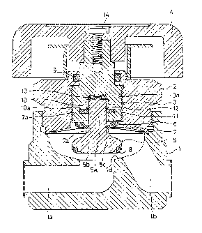
Fig. 1 is a longit-~1 n~l sectional view of a metal diaphragm
type valve employing a seal structure according to a first
embodiment of the invention wherein the inner peripheral edge of
a metal diaphragm 7, the inner peripheral edge of a deflection
limiter 6, and a seat holder 5 are integrally affixed by welding.
The weld eliminates the requirement of any mechanism for clamping
(gripping) of the inner peripheral edge of the diaphragm, as used
in the prior art.
The metal diaphragm valve comprises a body 1 having a fluid
inlet passage la, a fluid outlet passage lb, a valve chamber lc,
and a valve seat ld. A bonnet nut 2 is screwed into the body 1
and a stem 3 is screwed into and supported for vertical movement,
by the bonnet nut. A handle 4 is attached to the upper end of
-11-
.
CA 022~3988 1998-11-12
the stem 3 and a seat holder 5 is attached to the lower end of
the stem so as to move vertically therewith. A deflection
limiter 6 has a central opening and the upwardly projecting
support shaft 5a of a seat holder 5 extends through the opening.
The deflection limiter 6 rests on the diaphragm which in turn
rests on a shoulder or support step 5c provided on the lower
portion of the shaft 5a. The metal diaphragm 7 has an outer
peripheral edge gripped and supported between the body 1 and the
bonnet nut 2 as the bonnet nut is screwed into the body. The
inner peripheral edge of the diaphragm is welded to the seat
holder 5 and deflection limiter 6.
The stem 3 is made of stainless steel (SS316) in a nearly
columnar form, and an engaging recess 10, having an expanded
middle portion lOa, is formed in the lower part of the stem.
Screw threads 3a are formed on the outer circumference of
the stem 3, and engage screw threads 2a formed on the interior of
bonnet nut 2 so that the stem 3 is supported elevatably in the
bonnet nut. The stem 3 may be raised or lowered by rotating the
stem relative to the bonnet nut. The handle 4 is attached to the
stem by a screw 14 so that rotation of the handle raises or
lowers the stem relative to the bonnet nut.
An O-ring 9 is provided to prevent cont~min~nts from
-12-
CA 022~3988 1998-11-12
, . .~,
entering the valve between the bonnet nut 2 and the stem 3.
The seat holder 5 is made of metal such a9 stainless steel
(SS316L) and has, in addition to the upwardly projecting
cylindrical support shaft 5a, an expanded lower part 5b. The
support step 5c for supporting the diaphragm is formed at the
boundary of the columnar support shaft 5a and the lower part 5b.
The diaphragm support step comprises a flat annular surface
portion 5d and a smooth arcuate shoulder 5e formed continuously
therewith, as shown in Fig. 3.
A seat insert (seat) 8, made of a polymer or synthetic resin
or metal, is provided at the lower end of the lower part 5b.
The upper part of the support shaft 5a is inserted into
engaging recess 10 of the stem 3, and a washer 11 and a retaining
ring 12 secure the support shaft 5a within the expanded portion
lOa of the recess while permitting relative rotation between the
shaft and the stem. A bearing 13 may be provided between the
upper surface of support shaft 5a and the upper end surface of
recess 10 to reduce friction between the stem 3 and the support
shaft. This bearing may be omitted in some cases.
The deflection limiter 6 (Fig. 2) is made of metal such as
stainless steel (SS304L) in a circular dish form. An insertion
hole 6a is provided in the center of the deflection limiter and
-13-
CA 022~3988 1998-11-12
the support shaft 5a (Fig. 1) of the seat holder 5 extends
through the insertion hole.
The inner peripheral edge 6b of the deflection limiter 6 is
formed with a thickness t of about 2mm. The length ~ of the
peripheral edge 6b having the thickness t defines a weld zone W
(Fig. 3) where the deflection limiter is welded to the upper
surface of the metal diaphragm.
The lower side of the deflection limiter (left side as
viewed in Fig. 2) has a flat annular surface portion 6c of length
~0 larger than or nearly as large as, the length ~. A moderate
curvature 6d extends upwardly and continuously from the outer end
P of the flat portion 6c to the outer periphery of the deflection
limiter.
The ~etal diaphragm 7 is formed by overlaying a plurality of
(two or three) ultrathin metal plates (thickness: about O.1 to
0.2mm) in a dish form. The plates may be made of stainless steel
(SS316L), a Co-Ni alloy steel such as Elgiloy~, or the like.
Elgiloy~ contains C = 0.15, Mn = 1.5 to 2.5, Ni = 14 to 16, Cr =
19 to 21, Mo = 6 to 8, Be = 0.1 or less, Co = 39-41, and Fe =
remainder (all contents by wt.%). A mounting hole 7a is provided
at the center of the diaphragm for receiving the shaft 5a of the
seat holder 5. In this embodiment, the outer diameter of the
.
CA 022~3988 1998-11-12
diaphragm 7 is selected to be about 38mm.
The inner peripheral edge of the metal diaphragm 7 is, as
shown ln Fig. 3, positioned between the flat annular surface
portion 6c of the deflection limlter 6, and the flat annular
surface portion Sd of the diaphragm support step Sc on the seat
holder 5, and is welded to both the limiter and the support step.
As shown in Fig. 3, the inner peripheral edge of the
diaphragm 7, the flat portion 6c of the deflection limiter 6
abutting against the inner peripheral edge of the diaphragm 7,
and the flat portion 5d of the seat holder abutting the inner
peripheral edge of the diaphragm 7 are welded together by a weld
W. The weld is in ring form, extending around the whole
circumference of the deflection limiter 6 in the portion of
length ~. This integrally affixes, in an airtight manner, the
inner peripheral edge of the diaphragm 7, the inner peripheral
edge of the deflection limiter 6, and the flat portion 5d of the
seat holder 5.
Referring to Figs. 1 and 3, the valve operates in the
following m~nnPr. When the stem 3 is moved up or down by
rotating the handle 4, the seat holder 5 ascends or descends, and
the seat 8 contacts the valve seat ld or departs from the valve
seat and the fluid passage la is opened or closed so that fluid
-15-
CA 022j3988 1998-11-12
may flow between passages la and lb.
When the fluid passage la of the valve is open, the metal
diaphragm 7 returns to an initial state of upward curvature as
shown in Fig. 1, and almost no bending stress is applied to the
inner peripheral edge of the diaphragm. If, however, the
diaphragm 7 is pulled up at a time the valve is opened, a
downward bending stress is applied to the inner peripheral edge
of the diaphragm so that the diaphragm tends to bend downwardly
radially outwardly of the support step 5c. The resulting curved
portion of the diaphragm is supported by the arcuate shoulder 5e
on the seat holder 5. That is, the lower surface of the
diaphragm in the region A (Fig. 3) contacts and is supported by
the shoulder 5e.
On the other hand, when the valve is operated to close the
fluid passage la, an upward bending stress is applied to the
inner peripheral edge of the diaphragm. In this case, the upper
surface of the diaphragm in the region B contacts and i9
supported by the curvature 6d of the deflection limiter 6.
Thus, in the diaphragm valve of the invention, unlike the
conventional metal diaphragm type valve, the inner peripheral
edge of the diaphragm 7 is not clamped. Instead, the inner
peripheral edge of the diaphragm is supported by the curvature 6d
-16-
CA 022~3988 1998-11-12
of the deflection limiter 6 or the arcuate curvature 5e of the
seat holder 5 when the diaphragm is bent. Accordingly, bending
stress is not directly applied to the weld zone W. As a result,
cracks and the like are not formed in the weld zone.
S It should be noted that upon upward bending of the diaphragm
the bending begins at a point P where the flat surface 6c of the
deflection limiter joins the curved surface 6d, but upon downward
bending the diaphragm bends about point F where the flat portion
5d of the seat holder joins the arcuate surface 5e. Points P and
F are located at different distances (~O and (Q1) from the seat
support shaft 5a in the radial direction because the diameter of
the flat annular surface 6c of the deflection limiter is
different from the diameter of the flat annular surface 5d on the
seat holder. Thus, the diaphragm 7 bends at two different
positions A and B (Fig. 3) as compared to the conventional case
where bending occurs at the clamped portion only regardless of
the direction in which the diaphragm is flexed. Thus, the life
or durability of the diaphragm is improved substantially.
Moreover, since the weld zone W covers almost the whole area
of the flat portion 5d of the diaphragm support step 5c as shown
in Fig. 3, there is a gap G1 outward of where the weld W joins
the diaphragm and the support step 5c and the lower side of the
-17-
CA 022~3988 1998-11-12
_
diaphragm 7. This greatly enhances the fluid replacement
performance and the purging of waste gases from the valve.
In addition, since the inner peripheral edge of the
diaphragm 7, the deflection limiter 6, and the seat holder 5 are
integrally affixed in an airtight manner, the fluid in the valve
chamber lc will never leak out from the inner peripheral edge
portion of the diaphragm and the sealing performance is extremely
high.
Fig. 4 is a magnified partial view showing a second
embodiment of the invention. In this embodiment, the length ~0
of the flat portion 6c at the lower side of the deflection
limiter 6 is made shorter than in the case of Fig. 3 so that the
bending region A at the lower side of the diaphragm and the
bending region B at the upper side of the diaphragm during
operation of the diaphragm 7 are closer to each other as compared
to the embodiment of Fig. 3. Although this tends to reduce the
advantage of distributing stresses in the diaphragm depending on
the direction it is flexed, this arrangement tends to make more
equal the support provided to the diaphragm by the seat holder
and the deflection limiter.
Fig. 5 is a partial magnified view showing essential parts
of the metal diaphragm type valve according to a third embodiment
-18-
CA 022~3988 1998-11-12
of the invention. In this embodiment, the length ~0 of the flat
portion 6c at the lower side of the deflection limiter 6 is
selected longer than in the case of the first embodiment (Fig.
3), and a recess 6e is formed in the flat portion 6c, so that a
portion in the region of recess 6e does not contact the diaphragm
7.
In the embodiment of Fig. 5, the space between the bending
region A at the lower side and the bending region B at the upper
side during operation of the diaphragm 7 is wider, so that the
life span of the diaphragm is further increased.
An opening and closing durability test was conducted on a
valve constructed according to the first embodiment described
above. The diaphragm comprised two pieces of Elgiloy~ having an
outer diameter of 38mm and a thickness of 0.1 to 0.2 mm. The
fluid pressure of the fluid being controlled was 375psi. The
valve was cycled (opened and closed) at a rate of once/sec and
the diaphrasm did not crack or fail after 16470 cycles.
By contrast, the life of a conventional metal diaphragm type
valve is about 3000 cycles.
In the metal diaphragm valve of the invention, the bending
stress applied to the inner peripheral edge of the diaphragm 7
when the valve is closed is mainly supported at the lower side 6d
--19-
CA 022~3988 1998-11-12
of the deflection limiter 6, and the bending stress applied to
the inner peripheral edge when the valve is opened is mainly
supported at the arcuate shoulder 5e of the diaphragm support
step 5c. As a result, bending stress ls not directly applied to
the weld zone W of the inner peripheral edge of the diaphragm,
and cracks or the like do not form in the weld zone W.
Furthermore, the b~n~;ng stress receiving regions of the
diaphragm 7 (the regions A and B) differ and are spaced from each
other in the radial direction so that, depending on whether the
valve is opened or closed, the bending stress is dispersed in two
regions. Hence, as compared with the conventional case of where
the metal diaphragm 7 is clamped from above and below at one
position, breakage of the diaphragm i9 less likely to occur.
Moreover, as compared with the conventional case where
coupling of the seat holder and shaft is accomplished by a screw
mechanism clamping the diaphragm at one position, the number of
parts for forming the valve is smaller, and assembly of the valve
is much easier.
In addition, since the gap Gl between the lower side of the
metal diaphragm 7 and the upper side of the seat holder 5 is not
formed by a structure for clamping the diaphragm, the gap is
almost nil and very little fluid is caught therein. As a result,
-20-
CA 022~3988 1998-11-12
,
the fluid replacement performance and the cleaning/purging
performance of the inside of the valve are extremely ~nh~nced.
Although specific preferred embodiments have been described
to illustrate the novel aspects of the invention, it will be
S obvious that various additions and modifications may be made in
the described embodiments without departing from the spirit and
scope of the invention as defined by the appended claims.
We claim: