Note: Descriptions are shown in the official language in which they were submitted.
, CA 022~4281 1998-11-20
BACKGRO~ND OF THE lNv~;N-~LIoN
1. Field of the In~ention
The present invention relatès to a cooling element for shaft
furnaces provided with a refractory lining, particularly blast
furnaces. The cooling element is made of copper or a low copper
alloy and is provided with coolant ducts arranged in the interior
of the element.
2. Description o~ the Related Art
Cooling systems for the steel jackets of shaft furnaces,
particularly blast furnaces, are extensively described in "Stahl
und Eisen", 106 (1986), No. 2, pages 205-210. In addition to
cooling with so-called cooling boxes, in recent years cooling
with cooling plates, so-called staves, of cast iron and copper
has been used increasingly.
DE 39 25 280 discloses a cooling plate of grey cast iron in
which the cooling ducts are formed by cooling tubes which are
cast into the cast body. This cooling plate has the disadvantage
that, for preventing carburization, a coating of the cooling
tubes is required which impairs the thermal flux from the hot
,. . CA 022~4281 1998-11-20
side of the cooling plate or stave through the stave body and the
tube wall toward the cooling water. Accordingly, such staves
frequently reached high temperatures in excess of 760~C at which
decomposition of the pearlite occurs; cracks formed in the cast
body and the cast material in front of the cooling tubes wears
off even after a relatively short period of operation.
It has been attempted to achieve a longer durability of
these staves of cast iron by casting a plurality of cooling tubes
in the staves and to arrange these cooling tubes partially also
in different planes parallel to the hot side. This made the
staves of grey cast iron much more complicated and expensive, but
the durability of the staves did not increase to the same extent.
A significant improvement were the so-called copper staves
which are disclosed in DE 29 07 511 and are manufactured from
rolled copper material, wherein the cooling ducts are produced by
deep hole drilling parallel to the hot side. -This makes possible
an unimpeded thermal flux which is not impaired by any coating of
the tubes. Copper staves of this type are significantly cooler
on their hot sides than staves of grey cast iron, so that,
contrary to staves of grey cast iron, a stable crust of burden
material acting as insulation is formed on the hot side. This is
the reason why copper staves, even though the thermal
,. . CA 022~4281 1998-11-20
conductivity of this material is high, discharge less heat from a
blast furnace than staves of grey cast iron.
Another advantage of the copper staves is the fact that they
can be constructed thinner at about 150 mm than staves of grey
cast iron at about 250 mm. Consequently, at a given size of the
blast furnace, the useful volume is increased significantly when
copper staves are used.
However, the decisive advantage of the copper staves as
compared to staves of cast iron is the fact that they do not
exhibit the formation of cracks because of the material
properties and their surface wear is extremely low. In a long
term experiment extending over more than ten years, a material
loss of only 3 to 4 mm was observed. In the case of a rib height
of 50 mm, this results in a computed service life of about 150
years which substantially exceeds the service life of the
remaining blast furnace.
A disadvantage of the conventional copper staves is the fact
that they are still constructed of relatively substantial solid
material and, therefore, are heavy and expensive. The staves
must be processed to a significant extent because of the
necessary mechanical working on all sides, the cutting of
~- . CA 022~4281 1998-11-20
grooves, the deep hole drilling and the welding of the pipe
connections. The material removed by chip-removing processes
constitutes a substantial portion of the total weight and can be
sold only at a significantly lower price. Another disadvantage
is the fact that when deep hole drilling is carried out in excess
of 2 to 3 m depth, the duct diameters may not be less than a
certain dimension because otherwise there is the danger that the
drill runs off center. The cooling ducts produced in this manner
are larger than necessary; the same is true for the quantity of
cooling water because a minimum speed of about 1.5 m/sec is
, .
necessary for separating steam bubbles which may form at the tube
wall as a result of the high thermal load. Consequently, the
cooling water heating rates are uneconomically low.
,. CA 022~4281 1998-11-20
SUMMARY OF THE lNv~lION
Therefore, it is the primary object of the present invention
to provide a cooling element which, contrary to conventional
copper staves, uses significantly less material and requires less
processing, while still being stable and able to withstand the
rough operating conditions of a blast furnace, wherein the
cooling element can be mounted easily and has a service life
which is at least in the same order of magnitude as a blast
furnace plant.
Another object of the invention is to provide a suitable
flow cross-section for the cooling water which has a shape
deviating from the circular shape in order to achieve greater
heating rates for the cooling water without dropping below the
necessary minimum speed for the cooling water which is required
for separating and conveying away the steam bubbles which form at
the tube wall at high thermal loads.
Finally, the hot side is to be configured in such a way that
a surface is produced in an uncomplicated manner to which crusts
of burden material can adhere well.
. . CA 022~4281 1998-11-20
In accordance with the present invention, the cooling
element is composed of an extruded or rolled section which in the
interior thereof has a plurality of cooling ducts which are round
or have a shape which deviates from the circular shape. The
cooling element is provided with lateral webs. The cooling
element is equipped on the side facing away from the blast
furnace wall in vertical direction with at least one continuous
slag rib and the cooling element is equipped on the side facing
the blast furnace wall with at least one fastening rib.
In accordance with another embodiment of the present
invention, the cooling element is composed of an extruded
rectangular section having a groove and an extruded rectangular
section having a key. Cooling ducts are arranged in the
sections. The sections can be closed with an upper cover and a
lower cover, wherein in the upper cover and in the lower cover
each is laterally placed a pipe piece which is connected to the
cooling ducts of the cooling element.
While a conventional copper cooling element usually has four
parallel cooling ducts which extend in a copper block parallel to
the hot side, the cooling element according to the present
invention is composed of an extruded or rolled copper section
having an appropriately selected length, wherein the section has
. . CA 022~42X1 1998-11-20
one or more cooling ducts which are round or have a shape
deviating from the circular shape. By providing appropriate ribs
which extend from the cooling duct or ducts, the extruded or
rolled section has a sufficient stiffness necessary for
withstanding the rough operating conditions of a blast furnace;
this refers particularly to the fastening rib or ribs arranged on
the cooling element on the side facing the steel jacket of the
blast furnace. The ribs also serve for fastening the cooling
element to the steel jacket of the blast furnace. The lateral
webs of the co~per elements extending parallel to the steel
jacket of the blast furnace ensure that the complete surface area
of the steel jacket of the blast furnace is protected. The width
of the webs is selected in such a way that they overlap or extend
flush with the corresponding web of the neighboring element.
This makes it possible to also compensate for the diameter or
circumference differences in the conical portions of the steel
jacket of the blast furnace, i.e., at the bosh or the shaft. The
slag ribs on the hot side facing the interior of the furnace are
mechanically finished in such a way that they facilitate the
formation and stable adherence of a layer of solid or pasty
burden materials to the hot side of the copper cooling elements.
The copper cooling elements can be cut to the correct length
and bent on the construction site near to where they are to be
. . CA 022~4281 1998-11-20
assembled. For this purpose, the lateral webs at the upper and
lower sides of the individual copper cooling elements are
separated or removed by sawing, grinding or flame cutting, the
remaining circular or non-circular duct cross-section is bent
accordingly and is guided through the appropriate throughopening
in the steel jacket of the blast furnace. The cooling elements
are connected to the cooling circuit of the blast furnace through
intermediate pipe pieces for the cooling water flow. In order to
achieve diameters of the steel jacket openings which are as small
as possible, the duct cross-section within the steel jacket of
the blast furnace and outside thereof are returned by cold
shaping back to the round cross-section.
. .
For fastening the cooling elements to the steel jacket, the
cooling elements are provided with bores in the ribs extending
toward the steel jacket; support elements attached to the steel
jacket of the blast furnace engage in these ribs; the connection
between the ribs and the support elements is effected, for
example, by inserted and secured pins or bolts. After the
mechanical assembly, a refractory substance having a low thermal
conductivity is filled in the conventional manner into the space
behind the copper cooling elements.
,
. ~ CA 022~4281 1998-11-20
In the alternative embodiment of the present invention,
rolled or extruded copper sections are also used, wherein these
copper sections are rectangular and have at the sides thereof a
groove and key for an engaging connection between the cooling
elements.
By joining several such elements together, a continuous
copper block is formed with rectangular cooling ducts in the
block. This configuration of the cooling element sides results
in a seamless transition between the individual structural
components which is utilized for compensating for the conicitiy
of the blast furnace shaft and the blast furnace bosh.
Consequently, a continuous heat protection of the steel jacket of
the blast furnace is ensured.
Placed at the front ends of the cooling elements are similar
extruded sections having a U-shape, but with a greater cooling
duct cross-section. The cooling water enters and is discharged
through a pipe piece each at the upper portion and the lower
portion of the combined cooling element. Because the box-shaped
sections have to be joined together and the head and foot pieces
have to be manufactured, a cooling element constructed in
accordance with the present invention requires somewhat more
material and is somewhat more difficult to manufacture, however,
,. ~ CA 022~4281 1998-11-20
the cooling element according to the present invention is even
flatter than the copper cooling elements with the pipe cross-
section or crôss-sections and the attached ribs and, therefore,
can be adapted essentially to the curvature of the furnace wall.
The cooling element can be attached to the furnace wall in a
conventional manner by means of threaded blind-end bores in the
cooling element and by fastening screws extending through the
steel jacket of the furnace which can be made to be gas-tight at
the outer side by welding cover cups thereon.
-
The various features of novelty which characterize theinvention are pointed out with particularity in the claims
annexed to and forming a part of the disclosure. For a better
understanding of the invention, its operating advantages,
specific objects attained by its use, reference should be had to
the drawing and descriptive matter in which there are illustrated
and described preferred embodiments of the invention.
,. . CA 022~4281 1998-11-20
BRIEF DESCRIPTION OF THE DRAWING
In the drawing:
Fig. 1 is a cross-sectional view of a copper cooling element
with slag ribs;
Fig. 2 is a side view of a copper element with slag ribs;
Fig. 3 is a longitudinal sectional view of a copper cooling
element with slag ribs;
Fig. 4 is a cross-sectional view of a copper cooling element
composed of rectangular sections;
Fig. 5 is a side view of copper cooling elements of
rectangular sections placed one on top of the other;
Fig. 6 is a longitudinal sectional view of a copper cooling
element of rectangular sections;
Fig. 7 is a top view of the upper cover of the copper
cooling element of rectangular sections;
. CA 02254281 1998-11-20
Fig. 8 is a top view of the lower cover of the copper
cooling element of rectangular sections.
.. . CA 022~4281 1998-11-20
DESCRIPTION OF THE PREFERRED EMBODIMENTS
Fig. 1 of the drawing is a cross-sectional view of a cooling
element 1 composed of an extruded or rolled section which in the
interior thereof has one or more oblong cooling ducts 2 which may
be round or have a shape which deviates from the circular shape.
The cooling element 1 is provided with lateral webs 3 and
continuous slag ribs 4 are arranged on the side facing away from
the blast furnace wall 9 and extending in the vertical direction.
A fastening rib 5 is arranged on the side facing the blast
furnace wall 9.
The cooling element 1 is fastened by means of bolts 7 in
bores 6 of the fastening element 8, the blast furnace wall 9 and
the fastening rib 5. The space between the cooling element 1 and
the blast furnace wall 9 is filled with a refractory filling 10.
As illustrated in Fig. 2, the upper and lower ends of the
cooling element 1 with the cooling duct 2 are bent by 90~ in the
direction toward the blast furnace wall 9 and extend through
openings 19 of the blast furnace wall 9. The upper and lower
webs 3 and the slag ribs 4 continue to extend vertically and have
steps 18 at the ends thereof in order to be connected to the
. . CA 022~4281 1998-11-20
adjacent cooling element in such a way that the cooling elements
cover the entire surface area of the blast furnace. The cooling
element 1 is fastened to the blast furnace wall 8, 9 by a bolt 7
which extends through the fastening rib 5 and the fastening
element 8.
Fig. 3 of the drawing shows a longitudinal sectional view of
the cooling element 1 with an oval cooling duct 2. An elongated
fastening rib 5 is provided on the side facing the fastening
element 8 of the blast furnace wall 9. A bolt 7 is inserted
through a bore-6 in the fastening rib 5 and the fastening element
8 for fastening the cooling element to the blast furnace wall.
Fig. 4 is a top view of another alternative embodiment of a
cooling element 1 which is composed of a rectangular cooling
element 11 with a groove and a rectangular cooling element 13
with a key, wherein a cooling duct 12 is formed in each
rectangular cooling element 11 and 13.
The cooling element 1 is fastened to the steel jacket 9 of
the blast furnace by means of fastening elements 14. A filling
10 of refractory material is filled between the cooling element 1
and the steel jacket of the blast furnace.
14
CA 022~4281 1998-11-20
Fig. 5 is a side view of cooling elements 1, 11, 12, 13
fastened one above the other to the steel jacket 9 of the blast
furnace. The cooling element 1 is covered in a pressure-tight
manner by an upper cover 15 and a lower cover 17 provided with
pipe pieces 16 for the supply and discharge of coolant.
Recesses or steps 18 provided offset relative to each other
in the covers 15, 17 make possible an overlapping placement of
the cooling elements 1 at the steel jacket 9 of the blast
furnace.
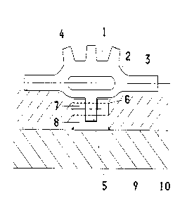
Fig. 6 is a longitudinal sectional view of a cooling element
1 which is ready for assembly. This cooling element 1 is
composed of a rectangular cooling element 11 with a groove, a
rectangular cooling element 13 with a key and with upper and
lower covers 15, 17, each provided with a pipe piece 16, and with
a recess or step 18.
The cooling water enters through the pipe piece 16 in the
lower cover 17 and, after flowing through the cooling ducts 12,
leaves through the upper cover 15, 16.
Figs. 7 and 8 are top views of the upper cover 15 and the
lower cover 17, respectively, each provided with a pipe piece 16
,. . CA 022~4281 1998-11-20
and segments of the cooling element 11 with a groove and a
cooling element 13 with a key, each including the two cooling
ducts 12.
While specific embodiments of the invention have been shown
and described in detail to illustrate the inventive principles,
it will be understood that the invention may be embodied
otherwise without departing from such principles.