Note: Descriptions are shown in the official language in which they were submitted.
CA 02254606 1998-12-17
NE-909
-1-
i TITLE OF THE INVENTION
2 "Ring Network for Sharing Protection Resource by Working
3 Communication Paths"
BACKGROUND OF THE INVENTION
Field of the Invention
6 The present invention relates generally to self-healing
7 communications networks, and more specifically to a ring topology
8 network which supports multiplex signals on protection communication
9 paths during failures by fast switching from working communication
paths.
11 Description of the Related Art
12 Ring topology networks, particularly, optical ring networks are
13 currently receiving attention because of the number of wavelengths that
14 can be multiplexed onto a single optical link is increasing due to recent
~ 5 innovative techniques. A number of technical publications deal with
16 this topic. A four-fiber ring network is discussed in a technical paper
17 "Multiwavelength Survivable Ring Network Architectures", A. F.
18 Elrefaie, Proceedings of ICC'93, pages 1245-1251,1993. According to
19 this publication, a loopback fault recovery method is described. In a
four-fiber ring network where optical links are interconnected by a
21 number of network nodes so that working rings are formed for
22 transmission of signals in opposite directions of the ring topology and
23 protection rings are formed for transmission of signals in opposite
24 directions of the ring topology. The protection rings respectively
correspond to the working rings and the direction of transmission of
26 each protection ring is also opposite to the direction of transmission of
2'7 the corresponding working ring. Optical paths are established on each
28 of the working and protection rings between network nodes. If a
29 working optical path between source and destination nodes fails, two
loopback points are formed, one on each end of the affected link of the
3 ~ working path, for connecting ends of the corresponding protection
CA 02254606 2002-06-26
71024-295
-2-
t optical path to unaffected sections of the working path so that a
2 recovery route is established between the source and destination nodes.
3 Since the loopback points are close to the location of the failure,
4 the recovery route can be quickly established by nodes adjacent to the
fault location and there is no need to exchange fault recovery messages
6 between nodes involved. However, the length of the recovery route is
'7 significantly Long. If a working path spans across one half of its ring,
8 the length of the recovery route would become one and half times the
9 whole length of the ring.
A two fiber ring network is described in a technical paper "An
Optical FDM-Based Self-Healing Ring Network Employing Arrayed
12 Waveguide Grating Filters and EDFA's with Level Equalizers", Hiromu
13 Toba et al., IEEE Journal on Selected Areas in Communications, VoL 14.
14. No. 5, pages 800-$13. In the two fiber ring network, one of the two rings
~ 5 is used as a working ring for transmission of signals in one direction of
16 the ring topology and the other for transmission of the same signals in
the opposite direction. A working path is established on the working
18 ring between two nodes and a corresponding protection path is
19 established between them on the protection ring. Under normal
2o conditions, signals from the source node are forwarded onto the
21 working path as well as onto the protection path. If the working path
22 fails, instant switching occurs at these two nodes to continue the
23 communication over the protection path.
24 Although all signals can be fully and quickly recovered on the
25 protection path, utilization
26 efficiency of the transmission mediums is Iow.
2~ SUMMARY OF THE INVENTION
28 - It is therefore an object of the present invention to provide a
29 ring topology network which requires short-length fault recovery routes
30 and ensures high efficient utilization of transmission mediums.
31 According to a first aspect of the present invention, there is
CA 02254606 1998-12-17
N E-909
-3-
1 provided a communications network comprising a plurality of
2 transmission links and a plurality of nodes for interconnecting the links
3 to form a working ring and a protection ring in a ring topology, and
4 establishing a plurality of working paths on the working ring and a
plurality of protection paths on the protection ring corresponding to the
6 plurality of working paths. In the network, one of the working paths
7 spans across first and second nodes of the plurality of nodes for
8 transmission of a signal in a first direction of the ring topology, and one
9 of the protection paths spans across the first and second nodes for
1 o transmission of a signal in a second direction of the ring topology
11 opposite to the first direction. The first and second nodes normally use
12 the working path that spans across them. Responsive to a failure of the
~ 3 working path, the nodes use the protection path that spans across them,
14 instead of the failed working path.
According to a second aspect, the present invention provides a
16 communications network comprising a plurality of transmission links,
7 and a plurality of nodes for interconnecting the links to form first and
18 second working rings and first and second protection rings in a ring
9 topology, and establishing a plurality of working paths on each of the
2o working rings and a plurality of protection paths on each of the
21 protection rings corresponding to the plurality of working paths. A first
22 working path of the first working ring spans across first and second
23 nodes for transmission of a signal in a first direction of the ring
24 topology, and a second working path of the second working ring spans
across the first and second nodes for transmission of a signal in a
26 second direction of the ring topology opposite to the first direction. A
27 first protection path on the first protection ring spans across the first
and
28 second nodes for transmission of a signal in the second direction of the
29 ring topology, and a second protection path of the second protection
ring spans across the first and second nodes for transmission of a signal
31 in the first direction of the ring topology. The first and second nodes
CA 02254606 1998-12-17
NE-909
-4-
1 normally use the first and second working paths, respectively.
2 Responsive to a failure of one of the first and second working paths, the
3 first and second nodes use a corresponding one of the first and second
4 protection paths, instead of the failed working path.
According to a third aspect, the present invention provides a
6 communications network comprising a plurality of transmission links;
7 and a plurality of nodes for interconnecting the links to form a working
8 ring and a protection ring in a ring topology, and establishing a
9 plurality of working paths on the working ring and a plurality of extra
traffic paths on the protection ring. One of the working paths spans
11 across first and second nodes for transmission of a signal in a first
~ 2 direction of the ring topology and one of the extra traffic paths spans
13 across the first and second nodes for transmission of a low-priority
14 signal in a second direction of the ring topology opposite to the first
direction. The first and second nodes normally use the working path
16 that spans across them. When a failure occurs in the working path, the
17 extra traffic path between the nodes is cleared and a short-haul
18 protection path is established for using it instead of the failed working
9 path. If the short-haul protection path is not successfully established
2o due to a further failure, other extra traffic paths are cleared and a long-
2 ~ haul protection path is established for using it instead of the failed
22 working path.
23 According to a further aspect, the present invention provides a
24 communications network in which first and second working paths are
assigned a first network resource and first and second protection paths
26 are assigned a second network resource. The first node normally uses
27 the first network resource and the first working path for transmission of
28 signals, and in response to a failure in the first ring, uses the second
29 network resource and the second protection path, instead of the first
network resource and the first working path. The second node
31 normally uses the second network resource and the second working
CA 02254606 1998-12-17
N E-909
-5-
1 path for transmission of signals, and in response to a failure of the
2 second ring, uses the first network resource and the first protection
3 path, instead of the second network resource and the second working
4 path.
According to a still further aspect, the present invention
6 provides a communications network in which first and second working
7 paths are assigned first and second network resources, respectively,
8 and first and second protection paths are assigned the second and first
9 network resources, respectively. The first node normally uses the first
0 network resource and the first working path for transmission of signals
11 and is responsive to a failure of the first ring to use the second
12 protection path instead of the first working path. The second node
~ 3 normally uses the second network resource and the second working
14 path for transmission of signals and is responsive to a failure of the
second ring to use the first protection path instead of the second
16 protection path.
17 According to a still further aspect, the present invention
~ 8 provides a network node for a ring topology network, the network
9 having first and second working rings and first and second protection
2o rings in a ring topology, and a plurality of working paths on each of the
21 working rings and a plurality of protection paths on each of the
22 protection rings corresponding to the plurality of working paths,
23 the network node comprising a first demultiplexer for receiving a
24 multiplex signal from one of the working paths for producing drop-off
signals, a first multiplexer for multiplexing add-up signals onto the
26 working path, a first path switch connected between the first
27 demultiplexer and the first multiplexer, a second demultiplexer for
28 receiving a multiplex signal from one of the protection paths for
29 producing drop-off signals, a second multiplexer for multiplexing add-
up signals onto the protection path, a second path switch connected
31 between the second demultiplexer and the second multiplexer,a
CA 02254606 1998-12-17
N E-909
-G-
1 transmit protection switch, a receive protection switch, and control
2 circuitry for monitoring the working path and controlling the transmit
3 protection switch so that one of the add-up signals is coupled to the
4 first multiplexer when no failure is detected in the working path and
coupled to the second multiplexer when a failure is detected in the
6 working path, and controlling the receive protection switch so that one
7 of the drop-off signals of the first multiplexer is received when no
8 failure is detected in the working path and one of the drop-off signals of
9 the second multiplexer is received when the failure is detected.
BRIEF DESCRIPTION OF THE DRAWINGS
~ 1 The present invention will be described in further detail with
12 reference to the accompanying drawings, in which:
13 Fig. 1 is a block diagram of a ring topology optical network
14 according to the present invention;
~ 5 Fig. 2 is a block diagram of an optical add-drop multiplexer of
6 Fig. l;
17 Fig. 3 is a flowchart of the operation of the monitor circuit of the
~ 8 add-drop multiplexer;
19 Fig. 4 is a schematic diagram illustrating multiple optical paths
established in one of the working rings and in one of the protection
21 rings of Fig. 1;
22 Fig. 5 is a schematic diagram of a two-ring topology network
23 according to a modified embodiment of the present invention;
24 Fig. 6 is a block diagram of an add-drop multiplexer of Fig. 5;
Fig. 7 is a schematic diagram showing routes followed by
26 signals of Fig. 6 that occur in the event of link failures;
2'7 Fig. 8 is a schematic diagram of a two-ring topology network
28 according to a further modification of the present invention;
29 Fig. 9 is a block diagram of an add-drop multiplexer of Fig. 8;
Fig. 10 is a schematic diagram showing routes followed by
31 signals of Fig. 9 that in the event of link failures;
CA 02254606 1998-12-17
N E-909
_7_
1 Figs. 11A and 11B are schematic diagrams of a four-ring
2 topology network according to a further embodiment of the present
3 invention;
Fig. 12 is a block diagram of an add-drop multiplexer used in
the embodiment of Figs. 11A and 11B;
6 Figs. 13A and 13B are flowcharts of the operation of the monitor
7 circuit of a destination node of Figs. 11A and 11B in the event of link
8 failures;
9 Fig. 14 is a flowchart of the operation of the monitor circuit of a
source node of Fig. 11B in the event of link failures; and
11 Figs. 15A,15B and 15C are block diagrams of optical protection
12 switches useful for universal applications for possible failures in a four-
13 ring topology network.
14 DETAILED DESCRIPTION
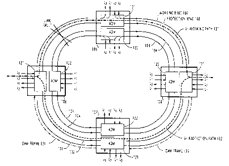
In Fig. 1, a wavelength-division multiplex (WDM) four- fiber ring
16 network of the present invention is illustrated. The network is made up
17 of a plurality of nodes 105 to 108 which interconnect optical fiber links
18 to form rings 101 to 104 in a ring topology. Rings 101 and 102 form a
19 first pair of working and protection transmission mediums,
respectively, and the rings 103 and 104 form a second pair of working
21 and protection transmission mediums, respectively. The directions of
22 transmission of the working and protection rings of each pair are
23 opposite to each other and the direction of transmission of the working
24 ring of the first pair is opposite to that of the working ring of the
second
pair.
26 Each network node has a first add-drop optical multiplexer 121
2'7 for processing optical signals which normally propagate in the
28 clockwise direction over the working ring 101 of the first pair and a
29 second ADM 122 for processing optical signals which normally
propagate in the counterclockwise direction over the working ring 103
31 of the second pair. In the event of a failure, the ADM 121 also processes
CA 02254606 1998-12-17
N E-909
_g_
1 signals propagating over the counterclockwise ring 102, while the ADM
2 122 processes signals propagating over the clockwise ring 104.
3 Each optical add-drop multiplexes of the network is connected to
4 a network element such as ATM (asynchronous transfer mode) switches
or SONET (Synchronous Optical Network) terminators to add up
6 incoming traffic signals of wavelengths ~.1 and ~ in the 1.5 ~.m region by
7 multiplexing them with other traffic signals and drop off traffic signals
8 of ~ and ~ in the 1.5 ~,rn region by demultiplexing them from other
9 traffic signals. In addition to the traffic signals, a supervisory or OAM
(operations, administration and maintenance) frame of wavelength ~,S in
11 the 1.3 ~.m region is multiplexed with the traffic signals.
~ 2 All optical add-drop multiplexers 121 and 122 of the network are
13 of identical construction. As shown in Fig. 2, each ADM 121 (122)
14 includes a working ADM processor 209 and a protection ADM
processor 210 of identical configuration, which are respectively
16 connected in the working ring 101 (103) and the protection ring 102
17 (104). Because of the identical configuration, the description that
~ 8 follows is only concerned with the ADM 121 for simplicity.
19 At the input of ADM processor 209, a WDM signal arriving on
the working ring 101 is supplied to an optical demultiplexer 300 where
21 the traffic signal is separated into wavelength components ~,1 and ~,Z
22 and fed to optical splitters 301 and 302, respectively, to drop off the
23 received signals. Optical path switches 305 and 306 are provided to
24 establish a junction point of an optical path or a source point of an
optical path for add-up signals supplied from the network element via
26 protection switches 211, 212. These path switches are controlled from an
2~ external source to exclusively supply an optical multiplexes 307 with
28 signals from the splitters 301, 302 or signals from the protection
29 switches 211 and 212.
In a similar manner, counterclockwise WDM signal propagating
31 over the protection ring 102 during a fault recovery period is supplied
CA 02254606 1998-12-17
N E-909
-9-
1 to an optical demultiplexer 300' of the ADM processor 210 where the
2 traffic signal is separated into wavelength components ~ and ~ and fed
3 to optical splitters 301' and 302', respectively. Optical path switches
4 305' and 306' are provided to establish a junction point of an optical
path or a source point of an optical path for add-up signals supplied
6 from the network element via protection switches 211, 212. These path
7 switches are controlled from an external source to exclusively supply
8 an optical multiplexes 30T with signals from the splitters 301, 302 or
9 signals from the protection switches 211 and 212.
OAM command frames of the working ring are separated by the
11 demultiplexer 300 and applied to a monitor circuit 215, where their
12 contents are examined to control optical protection switches 211, 212,
13 213 and 214. OAM command are also transmitted on the protection ring
14 102 when it is used if the working route fails. OAM command frames
on the protection ring 102 are detected by the demultiplexer 300' and
16 applied to the monitor circuit 215 to control the optical protection
17 switches 211, 212, 213 and 214 when the failed route is repaired.
18 Monitor circuit 215 also relays the received OAM frame to downstream
9 node as indicated by broken lines 250.
To the inputs of protection switches 213 and 214 are connected a
21 plurality of splitters 217 to 220. Splitters 217 and 218 extract a greater
22 portion (90%) of energy of the drop-off signals from splitters 301' and
23 301 for coupling to the protection switch 214 and supply the remainder
24 energy to the monitor circuit 215. Likewise; splitters 219 and 220 extract
a greater portion of energy of drop-off signals from splitters 302' and
26 302 for coupling to the protection switch 213 and supply the remainder
27 energy to the monitor circuit 215. In response to control signals from
28 the monitor circuit 215, the protection switch 213 selects one of the
29 outputs of splitters 219 and 220 for application to the network element,
and the protection switch 214 selects one of the outputs of splitters 218
31 and 219 for coupling to the network element.
CA 02254606 1998-12-17
N E-909
-10-
1 Fig. 3 is a flowchart of the operation of the monitor circuit 215 of
2 each add-drop multiplexer during a fault recovery process.
3 A fault recovery process begins in a network node when the
4 monitor circuit of the node determines that the bit error rate of an
incoming optical signal that terminates to its own node has dropped
6 below a predefined threshold value (step 351). If this is the case, the
7 monitor circuit recognizes that its own node is a destination node of a
8 working optical path from the source node of the monitored signal and
9 a link failure has occurred in that working path. Flow proceeds to step
352 to formulate and transmit an OAM frame to an adjacent node over
11 an unaffected section of the working ring, containing the source node
12 identifier in the destination address (DA) field of the frame, the path
13 identifier of the failed working path and the type of fault. At step 353,
14 the monitor circuit of the destination node performs protection
switching from the failed working path to a protection path pre-
16 established between the source and destination nodes.
17 If the decision at step 351 is negative or if the monitor circuit of
18 the destination node has performed protection switching at step 353,
19 flow proceeds to step 354 to monitor OAM frames. If an OAM frame
destined for another node is received, flow proceeds to step 355 to
21 forward the frame onto an unaffected section of the working ring so that
22 the frame is relayed to an adjacent node.
23 If the decision at step 354 is negative or the monitor circuit has
24 relayed an OAM frame to an adjacent node, flow proceeds to step 356 to
check to see if an OAM frame destined for its own node is received. If
26 so, the monitor circuit of the source node recognizes that a link failure
27 has occurred in a working path identified by the path identifier of the
28 received frame and performs protection switching to the pre-
29 established protection ring and returns to the starting point of the
routine. If the decision at step 356 is negative, flow returns to step 351.
31 Therefore, if a link failure occurs between nodes 105 and 106 as
CA 02254606 1998-12-17
N E-909
-11-
1 shown in Fig. 1, the WDM signal normally propagating clockwise over
2 an optical working path 131 from source node 106 to destination node
3 108 is affected and protection switching occurs at source and
4 destination nodes 106 and 108 to switch over a protection optical path
132 to transport the affected signal in the counterclockwise direction.
6 More specifically, the working path 131 is established by ADMs
7 121 of nodes 10b,105 and 108 as follows.
8 At the source node 106, the switches 305, 306 set up connections
9 between the protection switches 211, 212 and the multiplexer 307 so that
o source signals of wavelengths ~ and ~ from the network element are
11 passed through the upper positions of protection switches 211, 212 and
12 forwarded onto the working ring 101. At the intermediate node 105, the
13 path switches 305, 306 set up connections between the splitters 301, 302
14 and the multiplexer 307 to forward the received signals onto the ring
101 in the clockwise direction. At the destination node 108, the
16 protection switches 213, 214 are operated to select the outputs of
17 splitters 220 and 218 for coupling the terminating signals received via
18 splitters 301, 302 to the network element, while turning the path
19 switches 305, 306 to cut off connections between the splitters 301, 302
and the multiplexer 307.
2 ~ Optical protection path 132 is established by operating the path
22 switches 305', 306' of intermediate node 107 to set up connections
23 between the splitters 301', 302' and the multiplexer 30T. At the source
24 node 106, the path switches 305' and 306' set up connections between
the protection switches 211, 212 and the multiplexer 30T in preparation
26 for possible transmission of the source signals to the protection ring 102
27 when these protection switches are switched to the lower position.
28 At the destination node 108, the path switches 305', 306' are
29 turned off to prevent no signals from being applied from these switches
to the multiplexer 30T in preparation for possible reception of the
31 terminating signals from the protection ring 102 via the demultiplexer
CA 02254606 2002-06-26
71024-295
-12-
1 300' when the protection switches 213 and 214 are switched to their
2 lower position.
3 The operation of the flowchart of Fig. 3 will be described below
by assuming that a link failure occurs between nodes 105 and 106 on the
working path 131 as indicated in Fig. 1.
6 First, the monitor circuit 215 of the destination node 108 detects
7 the occurrence of the link failure when it determines that the bit error
8 rate of the signals from splitters 218, 220 has dropped below the
9 threshold value (step 351). Monitor circuit 215 of the destination node
i0 108 formulates an OAM frame 133, containing the identifier of source
11 node 106 and the identifier of the failed path 131 and a protection
12 switching command. This frame is transmitted over an unaffected
13 section of working ring 101 to node 107 (step 352), where the monitor
14 circuit 215 of its ADM 121 examines the destination address field
of the frame for coincidence with its own node identifier.
16 Recognizing that the frame is not destined for the node 107 (step 354), it
17 retransmits this frame to the source node 106 as an OAM frame 134 over
18 an unaffected section of working ring 101 (step 355).
19 Meanwhile, the monitor circuit 215 of the destination node 108
operates the protection switch 214 to connect the output of splitter 217
21 to the network element (step 353) so that it can receive the WDM signal
22 which will be transmitted on the protection path 132 from the source
23 node 106.
24 When the monitor circuit 215 of source node 106 receives the
OAM frame 134 (step 356), it recognizes that the frame is destined for its
26 own node and a link fault has occurred and provides switching to a
27 protection path by operating its protection switches 211, 212 (step 35~.
28 As a result, the signals from the source node 106 are coupled through
29 the protection switches 211, 212 and path switches 355', 356' and
3o multiplexed by the multiplexes 30T into a WDM signal and forwarded
31 onto the protection path 132 and transmitted in the counterclockwise
direction to the intermediate node 107 and relayed to the destination
CA 02254606 1998-12-17
N E-909
-13-
1 node 108.
2 When the link failure is repaired, the network configuration is
3 restored by switching from the protection ring to the working ring in
4 preparation for a possible link failure.
If the link failure between nodes 105 and 106 is due to a cable
6 cut, the WDM signal normally propagating counterclockwise on a
7 working path established in the ring 103 is also affected. In this case,
8 the nodes 108 and 106 acts as source and destination nodes to perform
9 the routine of Fig. 3, with node 107 also acting as an intermediate node,
to switch over the signal to a protection path pre-established in the ring
11 104.
12 It is seen that the length of protection path 132 for recovering a
~ 3 fault is significantly reduced in comparison with the prior art loopback
14 four-fiber ring network. In a similar situation to that shown in Fig.1,
~ 5 the loopback fault recovery scheme would require nodes 105 and 106 to
16 form two loopback points, one on each end of the failed link, so that a
17 recovery path is established starting from node 106, passing through
18 nodes 107 and 108 to node 105, where it is looped back to the node 108.
9 The present invention thus allows implementation of a four-fiber ring
network having a long-haul ring structure with a small number of
21 intermediate nodes.
22 If the network uses a frame format in which the bit position
23 indicates information, the destination node identifier and the path
24 identifiers may be respectively assigned first and second eight bits of
the section overhead and the command may be represented by one bit.
26 In the above-mentioned example case, only one working optical path is
27 affected by a link failure for the purpose of describing the basic
28 operation of each node during a fault recovery process. If a number of
29 optical paths are affected simultaneously, it is advantageous for a
source node to formulate an OAM frame by concatenating such bit
31 sequences in number corresponding to the number of affected paths, or
CA 02254606 1998-12-17
N E-909
-14-
1 wavelengths. Using a single command message, protection switching
2 can be performed simultaneously on as many optical paths as there are
3 different wavelengths in a fiber link.
4 Fig. 4 shows an example of path configuration of the present
invention in which a number of optical paths are established in the
6 working ring 101 using a single wavelength. Since the network is of the
7 symmetrical structure with respect to the direction of transmission, the
8 path configuration of the second pair of rings 103 and 104 is identical to
9 that of the first pair, only one pair of rings 101 and 102 is illustrated.
o As illustrated, optical paths 401 to 404 are established in the
11 clockwise working ring 101 using wavelength 7~,1. Since it is possible to
12 use other wavelengths to establish additional optical paths in the
13 network, only one wavelength is shown to describe the advantage of the
14 present invention.
Optical paths 401 to 404 are established on the working ring 101
6 between adjacent nodes in the clockwise direction of transmission.
17 Corresponding to the working optical paths 401 to 404, protection
18 optical paths 401' to 404' are respectively established in the
9 counterclockwise ring 102 in such configuration that they support their
counterparts in the event of a link failure. Specifically, protection path
21 401' extends counterclockwise from node 106 to node 105 via nodes 107
22 and 108, path 402' extending from node 105 to node 108 via nodes 105
23 and 107, path 403' extending from node 108 to 107 via nodes 105 and
24 106, and path 404' extending from node 107 to 106 via nodes 108 and
2s 105.
26 Establishment of more than two optical paths on a single
2'7 wavelength resource results in an optical ring topology network of high
28 utilization efficiency as compared with the conventional two-fiber ring
29 network where only one optical path is allowed for both working and
protection rings and the wavelength resource of the protection ring is
31 exclusively used by the working ring. In the present invention, the
CA 02254606 1998-12-17
N E-909
-15-
wavelength resource of the protection ring is not exclusively used by
2 the working ring. Rather, it is shared by the optical paths in the working
3 ring.
4 Another important feature of the present invention is that, since
the distance travelled by the OAM frame is not greater than the length
6 of the ring and since intermediate nodes are not involved in protection
7 switching, the amount of time taken to complete a fault recovery
8 process is comparable to that of the conventional SONET four-ring
9 topology network.
0 In contrast with the conventional two-fiber ring network where
11 the protection ring is always used for transporting signals in a direction
12 opposite to that of the signals on the working ring, the present
13 invention provides a further advantage in that the normally unused
4 protection ring can be used for transporting low priority signals.
~ 5 In addition, difficulty exists in the prior art WDM ring-topology
16 network to perform OAM management functions on wavelengths using
17 a bundle of optical paths as a management unit. Such wavelength
18 management can be easily achieved by using the present invention in a
19 SONET environment since a bundle of paths can be used.
2o The cost of the ring-topology network of the present invention
21 can be reduced by multiplexing additional wavelengths ~,3 and ~,4 on
22 the working and protection rings 101 and 102, instead of using rings 103
2 3 and 104.
24 One embodiment of this two-fiber ring network is shown
25 schematically in Fig. 5. Each of the working and protection rings 101
26 and 102 is identically assigned four wavelengths ~,1 to ~,4. In each ring,
27 wavelengths 7~,1 and ~,2 are used to establish working paths and
28 wavelengths ~,3 and ~,4 are used to establish protection paths. The
29 working paths in the ring 101 are used to carry optical signals in the
30 clockwise direction and those in the ring 102 are used to carry optical
31 signals in the counterclockwise direction. Thus, if the two-ring
CA 02254606 1998-12-17
NE-909
-1G-
topology network has two nodes A and B as illustrated in Fig. 5, two
2 working paths and two protection paths can be established between
3 nodes A and B in each of the rings 101 and 102. If wavelength 7~,1 is used
4 for communication between nodes A and B, they use rings 101 and 102
respectively for their normal transmission.
6 Node A is provided with protection switches 501 and 502 and a
7 wavelength converter 503, and node B is likewise provided with
8 protection switches 505 and 506 and a wavelength converter 507. During
9 normal operation, all switches are positioned to the left for transmission
1 o and reception of wavelength ~, so that the transmit signal from the
~ switch 501 of node A is sent through ring 101 and received by switch
12 506 at node B and the transmit signal from the switch 505 of node B is
13 sent through ring 102 and received by switch 502 at node A.
If node B detects the occurrence of a failure on the ring 101 by
examining its terminating signal from ring 101, it sends a command
16 message at wavelength ~,S on the ring 102 to node A and moves its
17 switch 506 to the right. In response, the node A moves its switch 501 to
18 the right. Assume that wavelength ~,3 is assigned to both nodes for their
19 transmission of signals during fault recovery time. The transmit signal
2o of node A is now coupled through the switch 501 to the wavelength
2 ~ converter 503 where its wavelength is converted from ?~,1 to ~3. The ~,3-
22 transmit signal is then applied to the protection path established on
23 wavelength ~ in the ring 102 and transmitted in the counterclockwise
24 direction. At node B, the wavelength of this signal is received through
the switch 506. Since the transmit signal of the node B is unaffected,
26 both nodes maintain their switches 502 and 505 in the left position.
27 Thus, the transmit signals of both nodes propagate in the same
28 counterclockwise direction over the ring 102 when the ring 101 fails.
29 Although the wavelength ~ from ring 102 is different from that
3 0 normally received through ring 101, the node B treats it as if it has the
31 same wavelength as that normally used.
CA 02254606 1998-12-17
NE-909
-17-
1 On the other hand, if the node A detects the occurrence of a
2 failure on the ring 102 while it is using the ring 101 for normal
3 transmission, it sends a command message on the ring 101 to node B
4 and moves its switch 502 to the right. In response, the node B moves its
switch 505 to the right. The transmit signal of node B is now coupled
6 through the switch 505 to the wavelength converter 507 where its
7 wavelength is converted from ~,1 to 7~,3. The ~,3-transmit signal is then
8 applied to the protection path established on wavelength ~,3 in the ring
9 101 and transmitted in the clockwise direction. At node A, the
wavelength of this signal is received through the switch 502. Since the
11 transmit signal of the node A is unaffected, both nodes maintain their
12 switches 501 and 506 in the left position. Thus, the transmit signals of
13 both nodes propagate in the same clockwise direction over the ring 101
14 when the ring 102 fails. Although the wavelength ~,s from ring 101 is
different from that normally received through ring 102, the node A
16 treats it as if it has the same wavelength as that normally used.
17 Fig. 6 shows details of each node of Fig. 5. Each node is provided
18 with add-drop multiplexers 600 and 610 which are respectively
19 associated with rings 101 and 102.
In the ADM 600, WDM signal on the ring 101 (102) is separated
21 by a demultiplexer 700 into four wavelength components. Wavelengths
22 ~,3 and ~,4 are supplied through splitters 701 and 702 to path switches
23 705 and 706, whereas ~,1 and ~,2 are supplied direct to path switches 703
24 and 704. Multiplexer 707 combines the outputs of the path switches 703
to 706 onto the ring 101 (102). Wavelength ~,3 and ~,4 from sputters 701
26 and 702 are respectively supplied to protection switches 619 and 620
27 via splitters 616 and 618. On the other hand, WDM signal on the ring
28 102 (101) is separated by a demultiplexer 710 of ADM 610 into four
29 wavelength components. Wavelengths 71,1 and ~ are supplied through
splitters 711 and 712 to path switches 713 and 714, whereas ~,3 and ~,4 are
31 supplied direct to path switches 715 and 716. Multiplexer 717
CA 02254606 1998-12-17
N E-909
-18-
1 multiplexes output signals of the path switches 713 to 716 onto the ring
2 102 (101).
3 Via splitters 615 and 617, wavelength signals 7~,1 and 7~.2 from
4 splitters 711 and 712 are respectively supplied to protection switches
619 and 620. Monitor circuit 630 receives replicas of the terminating
6 signals from splitters 615 to 618 to assess their quality and controls the
7 protection switches 619 and 620 to determine which one of the
8 terminating signals from rings 101 and 102 is to be supplied to the
9 network element.
Monitor circuit 630 further controls protection switches 611 and
~ 612 for coupling the transmit signals ~,1 and X1,1 of the local node to one
12 of the rings 101 and 102. When these protection switches are moved to
13 the lower position, signals ~,1 and 7~,2 are coupled to wavelength
14 converters 613 and 614 and converted to ~,3 and ~,4, respectively. The
outputs of wavelength converters 613, 614 are switched through the
16 path switches 715 and 716 to the multiplexes 717 for transmission on
17 ring 102 (101). When the protection switches 611, 612 are moved to the
18 upper position, the signals ~,1 and 7~,1 are coupled through the path
19 switches 703 and 704 to the multiplexes 707 for transmission on ring 101
(102).
21 Fig. 7 schematically shows routes followed by signals of Fig. 6 in
22 the case of node A of Fig. 5. During normal operation, transmit signal
23 7~,1 is coupled through protection switch 611 and path switch 705 and
24 forwarded onto ring 101. Terminating signal 7~,1 from ring 102 is
coupled through splitters 711 and 615 to protection switch 619 as
26 indicated by a solid thick line.
27 When the ring 101 fails, the protection switch 611 is moved to the
28 lower position, coupling the transmit signal to the wavelength
29 converter 613. Thus, the wavelength of the signal is converted to ~,3 and
transmitted through the path switch 715 to the ring 102 as indicated by a
31 thick broken line. Thus, the communicating nodes transmit their signals
CA 02254606 1998-12-17
N E-9 09
-19-
1 on different wavelengths, using the same ring 102.
2 If the ring 102 fails, instead of ring 101, the protection switch 619
3 is moved to the upper position. Since the ring 102 is not the working
4 ring of the local node, it is the remote node that switches its protection
switch 611. Thus, at the local node, the terminating signal ~,3 arrives on
6 ring 101 and is coupled through splitters 701 and 616 to protection
7 switch 619 and thence to the network element as indicated by a thick
8 broken line.
9 A modified form of the embodiment of Figs. 5 to 7 is shown in
Figs. 8, 9 and 10, in which parts corresponding in significance to those
11 in Figs. 5 to 7 are marked with the same numerals as those in Figs. 5 to
12 7.
13 As shown in Fig. 8, working optical paths are established with
14 wavelengths ~, 7~,2 on ring 101 and with wavelengths ~,3 and ~,4 on ring
102, instead of wavelengths ~ and 71,1. Protection optical paths are
16 established using wavelengths ~,3 and ~,4 on ring 101 and using ~,1 and
17 7~,2 on ring 102. This arrangement eliminates the need to use wavelength
18 converters.
19 For communication between nodes A and B, wavelengths 7v,1 and
2o ~,3 as well as rings 101 and 102 are assigned respectively to nodes A and
21 B. During normal operation, protection switches 501 and 502, at node A,
22 are arranged to transmit wavelength ~tl to ring 101 and receive
23 terminating signal ~,3 from ring 102. At node B, protection switches 505
24 and 506 are arranged to transmit wavelength ~,3 to ring 102 and receive
terminating signal ~1,~ from ring 101. During fault recovery time,
26 wavelengths ~,1 and ~,3 are also used by nodes A and B, respectively.
27 If node B detects the occurrence of a failure on the ring 101, it
28 sends an OAM frame at wavelength 71,3 on ring 102 to the node A and
29 moves its own switch 506 to the right. In response, the node A moves its
switch 501 to the right for coupling the transmit signal 7~,1 through
31 switch 501 to the protection path established on wavelength ~,1 in the
CA 02254606 1998-12-17
NE-909
-20-
1 ring 102 and transmitted in the counterclockwise direction. This signal
2 is received, at node B, through the switch 506. Since the transmit signal
3 of node B is unaffected, both nodes maintain their switches 502 and 505
4 in the left position. Thus, the transmit signals of both nodes propagate
in the same counterclockwise direction using different wavelengths
6 over the ring 102 when the ring 101 fails.
7 If the node A detects the occurrence of a failure on the ring 102
8 while it is using the ring 101 for normal transmission, it sends an OAM
9 frame at wavelength ~,1 on the ring 101 to node B and moves its switch
502 to the right. In response, the node B moves its switch 505 to the
11 right. The transmit signal ~,y at node B, is now coupled through the
12 switch 505 to the protection path established on wavelength ~ in the
13 ring 101 and transmitted in the clockwise direction. At node A, this
14 signal is received through the switch 502. Similar to Fig. 5, when the
ring 102 fails, both nodes maintain their switches 501 and 506 in the left
16 position and the transmit signals of both nodes propagate in the same
17 clockwise direction over the ring 101.
18 As illustrated in Fig. 9, each node of Fig. 8 is similar in
19 configuration to that of Fig. 6 except that wavelength converters 613 and
614 are dispensed with and splitters 711' and 712' are connected to
21 receive wavelength signals ~,3 and ~,4 from demultiplexer 710 for
22 coupling to sputters 617 and 615.
23 Routes that are followed by the signals of Fig. 9 are
24 schematically show in Fig.10 in the case of node A of Fig. 8. During
normal operation, transmit signal ~,1 is coupled through protection
26 switch 611 and path switch 705 to ring 101. Terminating signal ~ from
27 ring 102 is coupled through splitters 711 and 615 to protection switch
28 619 as indicated by a solid thick line.
29 When the ring 101 fails, the protection switch 611 is moved to the
lower position, coupling the transmit signal through path switch 713 to
3 ~ the ring 102 as indicated by a thick broken line. Thus, the
CA 02254606 1998-12-17
N E-909
-21 -
1 communicating nodes transmit their signals on wavelengths ~ and 7~,3,
2 using the same ring 102.
3 If the ring 102 fails, instead of ring 101, the protection switch 619
4 is moved to the upper position. Since the ring 102 is not the working
ring of the local node A, it is the remote node that switches its
6 protection switch 611. Thus, at the local node, the terminating signal ~,3
7 arrives on ring 101 and is coupled through splitters 701 and 616 to the
8 network element as indicated by a thick broken line.
9 The following description is again concerned with a four-fiber
o ring network. In this network, low priority signals, or extra traffic are
11 carried by protection rings 102 and 104. Fig. 11A shows one example of
~ 2 such a four-ring topology network in which extra traffic is carried on an
13 extra-traffic path 1101 on ring 104 between nodes 106 and 107 (shorter
14 side of a ring) and on a extra-traffic paths 1102,1103 and 1104 on ring
~ 5 102 between these nodes (longer side of the ring) as indicated by thick
16 solid lines.
7 Since the extra-traffic paths must be cleared before a protection
~ 8 path is established for normal traffic, complexity of protection switching
9 increases with the number of node-to-node hops and the number of
20 extra-traffic paths.
21 In addition, the shorter side of a ring between nodes 106 and 10~
22 has a smaller number of extra-traffic paths than its longer side. Thus, it
23 is advantageous to first clear the extra-traffic path on the shorter side
of
24 a ring when a working path 11 between nodes 106 and 107 fails. Extra-
25 traffic paths on the long side of the ring are cleared only if a failure
also
26 occurs on a protection path 14 or all links between nodes 106 and 107 as
27 shown in Fig. 11B.
28 Details of each of the nodes of Figs.11A and 11B are shown in
29 Fig. 12. To the working rings 101,103 are connected optical
30 demultiplexers 1201,1203 and optical multiplexers 1211, 1213. An
31 optical path switch 1221 is connected between these demultiplexers and
CA 02254606 1998-12-17
N E-9 09
-22-
1 the multiplexers. In a symmetrical relationship, a set of optical
2 demultiplexers 1201, 1203 and multiplexers 1212, 1214 are associated
3 with protection rings 102,104, with an optical path switch 1222 being
4 connected between these demultiplexers and multiplexers.
An outgoing optical protection switch 1231 is connected to the
6 inputs of all multiplexers via the path switches 1221 and 1222 and an
7 incoming optical protection switch 1232 is connected to the outputs of
8 all demultiplexers via splitters 1241-1244 and the path switches.
9 Similar to the previous embodiment, the path switches are used
to establish optical paths between nodes as well as to add up transmit
11 WDM signals to and drop off terminating WDM signals from the
12 transmission rings 101 to 104. Monitor circuit 1250 receives replicas of
13 the terminating signals from the splitters as well as OAM frames from
14 the demultiplexers to control the protection switches 1231 and 1232.
The operation of the monitor circuit 1250 of the nodes 107 and
16 106 will be described with the aid of the flowcharts of Figs. 13A,13B
17 and 14. It is assumed that the node 107 is a destination node
18 communicating with the source node 106 on the working path 11 and
9 detects a path failure caused by a link cut (see Fig. 11A) when the bit
2o error rate of the terminating signal appearing at one of the outputs of
21 demultiplexer 1201 falls below a threshold level. It is further assumed
22 that an additional link failure occurs in a protection path 14
23 simultaneously with the failure of working path 11 (see Fig. 11B).
24 As shown in Fig. 13A, when the monitor circuit 1250 of node 107
detects a higher-than-threshold bit error rate, it exits step 1301 and
26 enters step 1302 to formulate and transmit an ET-stop command
27 message onto the working path 13 to instruct the node 106 to stop
28 sending the extra traffic signal and to return an end-of-transmission
29 message when it has cleared the ET path 1101 to establish a protection
3 0 path 14.
CA 02254606 1998-12-17
NE-909
-23-
1 Node 107 then begins a timing action (step 1303) and proceeds
2 to decision step 1304 to check to see if an end-of-transmission message
3 is received from the node 106. If this message is received, flow proceeds
4 from step 1304 to step 1305 to forward a switchover command message
on the working path 13 to instruct the node 106 to switch from the failed
6 path 11 to the protection path 14. Node 107 starts a timing action at step
7 1306 and waits for a switchover complete message from the node 106
8 (step 130. If this switchover complete message is received, flow
9 proceeds from step 1307 to step 1308 to switch from the failed path 11 to
the protection path 14, and returns to the starting point of the routine.
11 If an end-of-transmission message is not received from the node
12 106 within the period of the timing action started at step 1303, or if no
13 switchover complete message is received from the node 106 within the
14 period of the timing action started at step 1306, flow proceeds from step
1310 or 1311 to decision step 1312 to check to see if an ET stop
16 command message is received from the node 106. If so, the node 107
17 clears the extra traffic path 1104 at step 1313, and starts a timing action
~ 8 at step 1314.
19 Node 107 proceeds from step 1314 to step 1315 to determine
whether a switchover command message is received from the node 106
21 through the protection ring 102.
22 If all links between nodes 106 and 10~ fail due to a cable cut, no
23 ET stop command message will be received and the decision at step
24 1312 is negative. In this case, the node 107 proceeds to step 1321 {Fig.
13B) to forward ET-stop command messages onto the ring 102 to the
26 nodes 108,105 and 106 to stop sending their extra traffic signals and
27 clear their extra-traffic paths 1102,1103 and 1104 (see Fig. 11B).
28 A timing action is then started (step 1322) to wait for end-of-
29 transmission messages from the nodes 108,105 and 106 {step 1323). If
all of these messages are received within the period of this timing
31 action, flow proceeds from step 1323 to step 1324 to forward a
CA 02254606 1998-12-17
NE-909
-24-
1 switchover command message on the ring 102 to the node 106 to
2 instruct it to switch from the failed path 11 to the protection path 12.
3 Otherwise, flow exits step 1326 and returns to the starting point of the
4 routine. At step 1325, the node 107 also switches from the failed path 11
to the protection path 12, and returns to the starting point of the routine.
6 Referring to Fig. 14, when the source node 106 receives an extra
traffic stop command message from the node 107 at step 1401, it
8 proceeds to step 1402 to clear the extra traffic path 1102. In addition, the
9 node 109 also receives this message and clears the extra traffic path
1101. Protection path 14 is thus established.
11 At step 1403, the node 106 begins a timing action and proceeds
~ 2 to decision step 1404 to check to see if a switchover command message
13 (see step 1305, Fig. 13) is received from the node 107. If so, it switches
14 from the failed path 11 to the protection path 14 (step 1405) and sends a
switchover complete message on the protection path 14 to the node 107
6 {step 1406), and returns to the starting point of the routine.
17 If the node 106 fails to receive the switchover command
18 message within the period of the timing action started at step 1403, flow
19 proceeds from step 1407 to step 1408 to forward ET-stop command
messages onto the ring 102 to the nodes 105,108 and 107 to stop
21 sending their extra traffic signals and clear their extra-traffic paths
1102,
22 1103 and 1104 (see Fig.11B).
23 A timing action is then started (step 1409) to wait for end-of-
24 transmission messages from the nodes 105,108 and 107 (step 1410). If
all of these messages are received within the period of this timing
26 action, flow proceeds from step 1410 to step 1411 to forward a
27 switchover command message on the ring 102 to the node 107 to
28 instruct it to switch from the failed path 11 to the protection path 12.
29 Otherwise, flow exits step 1413 and returns to the starting point of the
routine. At step 1412, the node 106 also switches from the failed path 11
31 to the protection path 12, and returns to the starting point of the
routine.
CA 02254606 1998-12-17
N E-9 09
- 25 -
1 Returning to Fig. 13, the node 107 receives this switchover
2 command message of step 1411 from the node 106 within the period of
3 the timing action started at step 1314, and proceeds to step 1316 to
4 switch from the failed path 11 to the protection path 12, and returns to
the starting point of the routine. If no switchover command message is
6 received within the period of the timing action started at step 1314, the
7 node 107 recognizes that no available path is present for recovering the
8 faults, and returns to the starting point of the routine from step 1317.
9 It is seen therefore that in a four-ring topology network where a
number of extra traffic paths are established on protection routes, the
11 extra traffic paths on a short protection route are first cleared to
12 establish a short protection path. If this protection path is not
~ 3 established within a prescribed interval due to an additional failure,
4 then the extra paths on a longer route are cleared to establish a longer
protection path.
6 Fig. 15A shows details of the transmit protection switch 1231 and
17 the receive protection switch 1232 of Fig. 12. Because of the
18 bidirectional characteristic of photonic devices such as optical couplers
9 and optical switches, it is advantageous for universal applications that
each of these transmit and receive protection switches can be
21 constructed of identical configuration for possible failures.
22 A multiport optical coupler, for example, can be used as an
23 optical splitter because a light beam incident on one of its ports appears
24 equally at the other ports. It can also be used as an optical combiner or
multiplexer if two or more light beams are incident on a number of
26 input ports, they are combined together and appears at an output port.
27 For simplicity, optical paths from node A to node B only are
28 illustrated in a four-ring topology network, using two working rings
29 101 and 103 and two protection rings 102 and 104. It should be
appreciated that the same four rings can also be used by optical paths
31 from node B to node A. The transmit protection switch 1231 and the
CA 02254606 1998-12-17
N E-909
-26-
1 receive protection switch 1232 are located in the nodes A and B,
2 respectively.
3 Within the node A, the optical protection switch 1231 includes a
4 pair of optical couplers 1501 and 1502 which act as optical splitters on
two transmit for dividing each signal into two routes. The outputs of
6 splitter 1501 are connected to a 1 x 3 optical switch 1503 and a 1 x 2
7 optical switch 1504 and the outputs of splitter 152 are connected to a 1 x
8 3 optical switch 1504 and a 1 x 2 optical switch 1505. These optical
9 switches are controlled by the monitor circuit 1250.
The outputs of optical switch 1503 lead to optical combiners
11 1507,1508 and 1509, the outputs of optical switch 1504 leading to
12 optical combiners 1507 and 1508. In a symmetrical configuration, the
13 outputs of optical switch 1505 lead to optical combiners 1510,1509 and
14 1508, protection paths are used by the outputs of optical switch 1505
leading to optical combiners 1510 and 1509. Optical combiners 1507 to
16 1510 are connected to rings 101,104,102 and 103, respectively.
17 Within the node B, the optical protection switch 1232 includes
18 optical sputters 1521 to 1524 respectively connected to rings 101,104,
19 102 and 103. Splitter 1521 has two outputs connected to a 3 x 1 optical
switch 1525 and a 2 x 1 optical switch 1526. Splitter 1522 has three
21 outputs connected to switches 1525,1526 and a 3 x 1 optical switch 1528.
22 The outputs of optical switches 1525 and 1526 are connected to a
23 combiner 1529. In a symmetrical manner, splitter 1524 has two outputs
24 connected to the switches 1528 and 1527, and the splitter 1523 has three
outputs connected to the switches 1525, 1527 and 1528. The outputs of
26 optical switches 1527 and 1528 are connected to a combiner 1530.
27 For normal communication, a first transmit signal from node A is
28 forwarded onto working ring 101 via switch 1503 and combiner 1507
29 and received at node B via splitter 1521 and switch 1525, as indicated by
3o a thick broken line 1541. A second transmit signal is forwarded onto
31 working ring 103 via switch 1506 and 1510 and received at node B via
CA 02254606 1998-12-17
N E-909
- 27 -
1 splitter 1524 and switch 1528, as indicated by a thick broken line 1542.
2 If a cable fault occurs and all rings that span between nodes A
3 and B are cut off as indicated in Fig.15A, the first transmit signal on
4 route 1541 is affected while the second transmit signal remains
unaffected. The monitor circuit at node B detects that the signal on
6 route 1541 has failed and examines the supervisory OAM frames
7 transmitted on wavelength 7v5 and knows that portions of all rings that
8 span across nodes A and B have failed. At node B, the switch 1525 is
9 moved to the leftmost position to receive the affected signal from
1 o protection ring 102 via splitter 1523. In addition, the node B instructs
11 the node A to move its switch 1503 to the rightmost position to forward
12 the first transmit signal onto the protection path 102 via combiner 1509.
13 In this way, an alternate route is established as indicated by a thick line
14 1550.
If a link failure occurs on the working ring 101, affecting only one
16 working path as shown in Fig.15B, the monitor circuit at node B detects
17 that the signal on route 1541 has failed and examines the supervisory
18 OAM frames and knows that the signal on route 1541 only has failed.
19 Node B causes the switch 1525 to move to the center position to receive
the affected signal from protection ring 104 via splitter 1522. In
21 addition, the node B instructs the monitor circuit at node A to move its
22 switch 1503 to the center position to forward the first transmit signal
23 onto the protection path 104 via combiner 1508. In this way, an
24 alternate route is established as indicated by a thick line 1551.
The optical protection switches can be modified as shown in Fig.
26 15C. In this modification, the splitters 1529 and 1530 of Figs. 15A and
27 15B are not used. Instead, the outputs of optical switches 1525 to 1528
28 are directly used as inputs of a network element. Monitor circuit 1250 is
29 arranged to detect a device fault in the protection switches. If the
working optical switch 1525 or 1528 fails, the monitor circuit controls
31 the spare switch 1526 or 1527 to divert the received signal from the
32 failed device.