Language selection

Search

Patent 2255240 Summary

Third-party information liability

Some of the information on this Web page has been provided by external sources. The Government of Canada is not responsible for the accuracy, reliability or currency of the information supplied by external sources. Users wishing to rely upon this information should consult directly with the source of the information. Content provided by external sources is not subject to official languages, privacy and accessibility requirements.

Claims and Abstract availability

Any discrepancies in the text and image of the Claims and Abstract are due to differing posting times. Text of the Claims and Abstract are posted:

  • At the time the application is open to public inspection;
  • At the time of issue of the patent (grant).
(12) Patent: (11) CA 2255240
(54) English Title: CONCRETE REINFORCING BAR PROTECTIVE COVER
(54) French Title: CALOTTE DE PROTECTION POUR RONDS A BETON
Status: Expired and beyond the Period of Reversal
Bibliographic Data
(51) International Patent Classification (IPC):
  • E04C 5/20 (2006.01)
  • B65D 59/06 (2006.01)
  • E04C 5/16 (2006.01)
  • E04G 21/32 (2006.01)
(72) Inventors :
  • SCHIMMELPFENNIG, JERRY D. (United States of America)
  • POWELL, MARCUS WILLIAM (United States of America)
  • SYLVAN, RICHARD (United States of America)
  • SPENNER, DOUGLAS JAMES (United States of America)
(73) Owners :
  • LOMONT MOLDING, INC. D/B/A PARAGON PRODUCTS
(71) Applicants :
  • LOMONT MOLDING, INC. D/B/A PARAGON PRODUCTS (United States of America)
(74) Agent: SMART & BIGGAR LP
(74) Associate agent:
(45) Issued: 2001-03-27
(22) Filed Date: 1998-12-02
(41) Open to Public Inspection: 1999-06-11
Examination requested: 1999-04-14
Availability of licence: N/A
Dedicated to the Public: N/A
(25) Language of filing: English

Patent Cooperation Treaty (PCT): No

(30) Application Priority Data:
Application No. Country/Territory Date
08/988,738 (United States of America) 1997-12-11

Abstracts

English Abstract


A protective cover for the ends of reinforcing bars has a cylindrical tube
having upper and lower ends. A cap is mounted on the upper end of the tube
and is comprised of a continuous circular wall extending upwardly and
outwardly from the upper end of the tube, with a bottom covering the top of
the tube. A post extends upwardly from the center of the bottom, and a
plurality of spaced rib elements are secured to and extend radially outwardly
from the post for connection to the wall. A canopy is secured to the upper edge
of the wall and extends slightly downwardly therefrom. The canopy has a
circular perimeter which has a downwardly extending circular flange
extending therearound. The ribs are tied together by secondary ribs. Friction
bars are located within the tube to create friction between the tub and a bar
upon which it is mounted.


Claims

Note: Claims are shown in the official language in which they were submitted.

What is claimed is:
1. A protective cover for covering the end of a concrete reinforcing bar,
comprising, a cylindrical tube having an open lower end and an upper end, a
cap on the upper end of said tube, said cap including a continuous circular wallextending upwardly and outwardly from the upper end of said tube and having
a bottom covering the top of said tube, a post extending upwardly from said
bottom, a plurality of spaced rib elements secured to and extending radially
outwardly from said post for connection to said wall.
2. The device of claim 1 wherein said wall has an upper edge, and a canopy
is secured to said upper edge and extends around said circular wall.
3. The device of claim 1 wherein said canopy has a circular perimeter with
a downwardly extending circular flange extending therearound.
4. The device of claim 1 wherein said ribs are tied together by secondary
ribs extending between said ribs.
5. The device of claim 2 wherein said canopy slopes downwardly and
outwardly from the upper edge of said wall.
6. The device of claim 1 wherein said protective cover is comprised of a
plastic material.
7. The device of claim 1 wherein vertical friction bars are secured within
said tube.

Description

Note: Descriptions are shown in the official language in which they were submitted.


CA 022~240 1998-12-02
TITLE: CONCRETE REINFORCING BAR PROTECTIVE COVER
BACKGROUND OF THE INVENTION
During construction of buildings, bridges and the like, it is common to
have the ends of steel reinforcing bars protruding from walls, columns and the
like during various stages of the construction. The protruding ends of the
reinforcing bars present a hazard to workmen who might fall on the bars.
Certain safety regulations in most locations now require that caps or
0 covers be placed on the ends of the protruding bars so as to protect workers
that might fall onto the bars. Occupational Safety and Health Standards
Boards (OSHA) have established certain standards for such caps to insure that
they are of sufficient strength and durability that the cap will maintain its
integrity even under all reasonable conditions that a person might fall on the
protruding bars. A typical standard would require that the caps be able to
withstand the impact of a 250 pound weight dropped from a height of 10 feet
without the protruding rod penetrating the cap. Minimum sizes of the cap are
also established so that the top of the cap is substantially greater than the
diameter of the bar on which it is mounted.
A typical existing cap for these purposes is illustrated in United States
Patent No. 5,568,708.
Some existing caps have a steel plate incorporated within a molded
plastic cap to add strength thereto and to further resist puncturing of the cap
when a load is imposed on the top of a rod. Such caps are relatively heavy for
2s handling in bulk quantities, and the shipping costs thereof are obviously
expensive. The incorporation of a metal plate in the plastic molding adds to
the expense of manufacture through both cost of material and assembly
expense.
It is, therefore, a principal object of this invention to provide a
30 reinforcing bar cover that will withstand existing drop tests without having a
steel plate inserted therein.
I

CA 022~240 1998-12-02
A further object of this invention is to provide a protective cover for
reinforcing bars that is relatively light in weight, and efficiently and
economically capable of being manufactured.
These and other objects will be apparent to those skilled in the art.
SUMMARY OF THE INVENTION
The protective cover for the ends of reinforcing bars of this invention has
a cylindrical tube having upper and lower ends. A cap is mounted on the
upper end of the tube and is comprised of a continuous circular wall extending
0 upwardly and outwardly from the upper end of the tube, with a bottom
covering the top of the tube. A post extends upwardly from the center of the
bottom, and a plurality of spaced rib elements are secured to and extend
radially outwardly from the post for connection to the wall.
A canopy is secured to the upper edge of the wall and extends slightly
downwardly therefrom. The canopy has a circular perimeter which has a
downwardly extending circular flange extending therearound. The ribs are
tied together by secondary ribs. Friction bars are located within the tube to
create friction between the tub and a bar upon which it is mounted.
BRIEF DESCRIPTION OF THE DRAWINGS
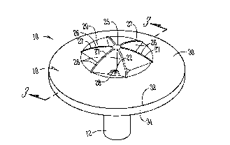
Fig. 1 is a top perspective view of the device of this invention;
Fig. 2 is a bottom perspective view thereof;
Fig. 3 is an enlarged scale sectional view taken on line 3-3 of Fig. 1;
Fig. 4 is a bottom plan view thereof; and
Fig. 5 is a top plan view thereof.
DESCRIPTION OF THE PREFERRED EMBODIMENT
The cover 10 is comprised of a vertical hollow tube 12 which has an
upper end 14 and an open lower end 16. A plurality of spaced vertically
30 disposed friction bars 17 are formed on the inner surface of tube 12 to

CA 022~240 1998-12-02
frictionally engage the end of a reinforcing bar which is inserted within the
tube.
A cap 18 is positioned on the upper end 14 of tube 12. A conically
shaped wall 20 extends upwardly and outwardly from the upper end 14 of the
tube. Wall 20 has a circular upper edge 21. A bottom 22 closes the upper end
14 of tube 12, and a center post 24 extends upwardly from the center of bottom
22. The upper end 25 of post 24 extends above the level of the upper edge 21 of
wall 20.
A plurality of flat ribs 26 with an arcuate upper edge 27 extend between
o the post 24 and the wall 20. The arcuate upper edge 27 of the ribs extends
from the upper end 25 of post 24 downwardly to the upper edge 21 of wall 20.
Secondary ribs 28 extend between adjacent ribs 26 adjacent the bottom of post
24 to further stiffen the ribs 28.
A canopy 30 extends from the upper edge 21 of wall 20 and extends in a
curved direction downwardly and outwardly away from the upper edge 21 of
the wall 20. The canopy 30 has a circular perimeter edge 32. A circular flange
34 extends uniformly downwardly from the perimeter edge 30. As shown in
Fig. 3, an upper end of a reinforcing bar 36 is forcibly inserted within the
interior of tube 12. The cover 10 thereupon protects a falling worker from
20 being injured or impaled on the upper end 38 of the bar 36.
The cover 10 is preferably comprised of a dense nylon material. The ribs
26 absorb the shock of a person falling thereon. The radial position of the ribsprevents them from collapsing. The canopy provides a surface area of at least
16 square inches, including the area occupied by the ribs 26 to provide an
25 adequate area to normally prevent substantial injury to a workman falling on
the cover.
Six ribs 26 are preferred and are spaced at 60~ apart from each other.
The ribs and the center post 24 gives an effective thickness of the cover 10 at
point of impact of approximately 3/4 inches. The secondary ribs 28 prevent the
30 ribs 26 from spreading in an impact situation.

CA 022~240 1998-12-02
The ribs 26 further strengthen the cover 10 under impact and prevent
the reinforcing bar from being able to tear through the cover if it should be
positioned slightly off center with respect to the bar. The overall conical shape
of the wall 20 helps to guide any falling object away from the rod 36 inside thes tube 12.
It is therefore seen that this invention will accomplish at least all of its
stated objectives.

Representative Drawing
A single figure which represents the drawing illustrating the invention.
Administrative Status

2024-08-01:As part of the Next Generation Patents (NGP) transition, the Canadian Patents Database (CPD) now contains a more detailed Event History, which replicates the Event Log of our new back-office solution.

Please note that "Inactive:" events refers to events no longer in use in our new back-office solution.

For a clearer understanding of the status of the application/patent presented on this page, the site Disclaimer , as well as the definitions for Patent , Event History , Maintenance Fee  and Payment History  should be consulted.

Event History

Description Date
Time Limit for Reversal Expired 2006-12-04
Inactive: IPC from MCD 2006-03-12
Letter Sent 2005-12-02
Grant by Issuance 2001-03-27
Inactive: Cover page published 2001-03-26
Pre-grant 2000-12-22
Inactive: Final fee received 2000-12-22
Notice of Allowance is Issued 2000-11-06
Letter Sent 2000-11-06
Notice of Allowance is Issued 2000-11-06
Inactive: Approved for allowance (AFA) 2000-10-25
Amendment Received - Voluntary Amendment 1999-08-05
Inactive: Cover page published 1999-07-01
Application Published (Open to Public Inspection) 1999-06-11
Letter Sent 1999-05-06
Request for Examination Received 1999-04-14
Request for Examination Requirements Determined Compliant 1999-04-14
All Requirements for Examination Determined Compliant 1999-04-14
Inactive: First IPC assigned 1999-01-27
Classification Modified 1999-01-27
Inactive: IPC assigned 1999-01-27
Inactive: Filing certificate - No RFE (English) 1999-01-12
Filing Requirements Determined Compliant 1999-01-12
Application Received - Regular National 1999-01-12

Abandonment History

There is no abandonment history.

Maintenance Fee

The last payment was received on 2000-12-01

Note : If the full payment has not been received on or before the date indicated, a further fee may be required which may be one of the following

  • the reinstatement fee;
  • the late payment fee; or
  • additional fee to reverse deemed expiry.

Please refer to the CIPO Patent Fees web page to see all current fee amounts.

Fee History

Fee Type Anniversary Year Due Date Paid Date
Application fee - standard 1998-12-02
Registration of a document 1998-12-02
Request for examination - standard 1999-04-14
MF (application, 2nd anniv.) - standard 02 2000-12-04 2000-12-01
Final fee - standard 2000-12-22
MF (patent, 3rd anniv.) - standard 2001-12-03 2001-11-26
MF (patent, 4th anniv.) - standard 2002-12-02 2002-11-19
MF (patent, 5th anniv.) - standard 2003-12-02 2003-11-17
MF (patent, 6th anniv.) - standard 2004-12-02 2004-11-08
Owners on Record

Note: Records showing the ownership history in alphabetical order.

Current Owners on Record
LOMONT MOLDING, INC. D/B/A PARAGON PRODUCTS
Past Owners on Record
DOUGLAS JAMES SPENNER
JERRY D. SCHIMMELPFENNIG
MARCUS WILLIAM POWELL
RICHARD SYLVAN
Past Owners that do not appear in the "Owners on Record" listing will appear in other documentation within the application.
Documents

To view selected files, please enter reCAPTCHA code :


To view images, click a link in the Document Description column. To download the documents, select one or more checkboxes in the first column and then click the "Download Selected in PDF format (Zip Archive)" or the "Download Selected as Single PDF" button.

List of published and non-published patent-specific documents on the CPD .

If you have any difficulty accessing content, you can call the Client Service Centre at 1-866-997-1936 or send them an e-mail at CIPO Client Service Centre.


Document
Description 
Date
(yyyy-mm-dd) 
Number of pages   Size of Image (KB) 
Abstract 1998-12-02 1 23
Description 1998-12-02 4 156
Claims 1998-12-02 1 31
Drawings 1998-12-02 3 49
Cover Page 2001-02-15 1 38
Cover Page 1999-06-25 1 39
Representative drawing 2001-02-15 1 6
Representative drawing 1999-06-25 1 7
Courtesy - Certificate of registration (related document(s)) 1999-01-12 1 115
Filing Certificate (English) 1999-01-12 1 163
Acknowledgement of Request for Examination 1999-05-06 1 179
Reminder of maintenance fee due 2000-08-03 1 109
Commissioner's Notice - Application Found Allowable 2000-11-06 1 163
Maintenance Fee Notice 2006-01-30 1 172
Correspondence 2000-12-22 1 30
Fees 2000-12-01 1 26