Note: Descriptions are shown in the official language in which they were submitted.
CA 02255258 1998-12-03
GUARD RAIL STUD ADAPTER
BACKGROUND OF THE INVENTION
1. Field of the Invention
This invention relates in general to scaffolding and shoring systems such as
those used
by building contractors, maintenance, repair personnel and others who are
required to work
on, build, paint and/or repair buildings and other structures. More
particularly this invention
relates to an attachment stud adapter for a safety guard rail for a
conventional scaffolding or
shoring system.
2. Discussion of Related Art
Conventional scaffolding or shoring systems have two spaced apart upright
members
secured in proper upright position by side crossed braces. In scaffolding
systems, floor boards
extend between the upright members and set upon horizontal supports provided
on each
upright member so that workers can stand and work on the stable, elevated,
temporary
flooring. However, workers and equipment still occasionally, for one reason or
another, fall
through the unprotected open space between the floor and the crossed braces of
the
scaffolding, resulting in serious injury. Consequently, OSHA, a federal
regulatory health and
safety agency, has imposed regulations on the industry that require suitable
safety guard rails
be installed on scaffolding systems to obstruct the open spaces between the
braces.
oao69ia.o6 2
CA 02255258 1998-12-03
In conventional shoring and scaffolding arrangements, the vertical support
elements
often are reinforced and stabilized by the use of additional crossed braces
extending between
them. Typically, these braces are secured to the vertical supports by bolt and
nut assemblies
with the bolts or studs, typically being welded or otherwise rigidly secured
in fixed positions
to the vertical support. With such arrangements, there has been at best
difficult and limited
flexibility in the positioning of the connection between the brace and the
support.
Consequently, conventional guard or safety rail constructions have their
drawbacks.
For example, installation of safety rails is often difficult, time consuming
and frustrating
because of typical, minor dimensional variations in scaffolding systems.
Furthermore,
workers often quickly assemble the scaffolding system high above the ground.
Thus, complex
guard rails and attachment devices increase the likelihood of an accident in
such an
environment. Complex attachment devices are also more likely to jam, or become
nearly
impossible to remove, when they become dirty or when corrosion sets in.
Therefore,
workmen commonly ignore the installation of safety guard rails, despite the
federal
requirements for their installation. Moreover, conventional scaffolding
systems do not have
retaining studs long enough to secure both the required cross braces and guard
rails.
One previously recognized solution, such as a guard rail which has C-shaped
attachment clamps, has the disadvantages of not being universal enough for all
applications
and having a multitude of moving parts and a relatively high cost.
0406914.06
CA 02255258 1998-12-03
The below-referenced U.S. patents disclose additional solutions that were at
least in-
part satisfactory for the purposes for which they were intended. The
disclosures of all the
below-referenced prior United States patents, in their entireties are hereby
expressly
incorporated by reference into the present application for purposes including,
but not limited
to, indicating the background of the present invention and illustrating the
state of the art.
United States Patent 4,004,393 discloses a shoring or scaffold system which
uses
demountable stacked scaffold sections, each having a pair of spaced-apart end
frames that are
demountably cross-connected with respect to each other. To provide strength
and support
rigidity, vertically adjustable, bracing members are utilized to extend from
the end frame of a
lower section across and in an interconnecting relation with an opposed end
frame of an
upper section. These bracing members have at one end a pivot mounting which
connects to
a horizontally extending connecting member of a frame of one section and at
the other end
have a latching arm which is provided with a group of spaced-apart latching
holes. The
latching holes latch with a single latching pin and latch keeper element which
are attached to
a secondary leg member of the opposed frame.
United States Patent x,145,030 discloses a guard rail post comprised of an
elongated
member having securing means comprised of a U-shaped channel and a post pin
for securing
a guard rail post to a vertical support member of the scaffold, positioning
means for
mounting the guard rail post in fixed relationship to a scaffold work
platform, and
oaob9m.ob 4
CA 02255258 1998-12-03
connecting means which includes pins having flip locks for connecting guard
rails to the post
at a fixed distance above the work platform.
United States Patent 4,430,019 discloses a wedge-and-bolt connector assembly
for
adjustably fixing a stud to a slotted thin-walled structure or the like for
use in a scaffolding
or shoring system to connect braces to vertical support elements. The support
elements have
T-slotted channels formed therein. The connector assembly includes a stud
having a
T-shaped head adapted to be received in a channel and a shank extending
through a channel
slot away from the head. The stud shank is formed of two parts, a stud section
and a
connector or extension section threadedly engaged to the stud section. The
free end of the
stud extension section may have a toggle thereon for securing the brace to the
stud shank. In
lieu of the toggle, a wedge may be provided with an L-shaped slide-lock
extension having a
first leg and a second leg. A free end of the stud is adjacent to the leg when
in the locking
position.
United States Patent 4,111,579 discloses a scaffold fitting attached to a
scaffold tube
which has a generally U-shaped clamping lever secured by a screw which passes
through an
intermediate aperture in the lever and which can be tightened to urge one end
of the layer
against a flanged member to clamp the latter directly against the scaffold
tube. The free end
of the lever has an arcuate abutment face which rests against the scaffold
tube.
0406914.06
CA 02255258 1998-12-03
In embodiments disclosed in the above-referenced patents, a device for
connecting
additional members to scaffolding and/or shoring is disclosed. Nevertheless,
these systems
generally have the disadvantage that they do not work well with a multitude of
conventional
scaffolding and/or shoring systems. Further, as indicated above, these systems
generally have
the disadvantage that they are costly and complex to manufacture and operate.
What is needed therefore is device for attaching additional members, like
guard rails,
to existing scaffolding and/or shoring systems that is simple and easy to use
in nearly any
environment. Further, what is also needed is a cost effective attachment
device for such
systems.
SUMMARY AND OBJECTS OF THE INVENTION
By way of summary, the present invention is directed to attachment device or
stud
adapter for guard rails and the like. A primary object of the invention is to
provide an
apparatus that extends the existing length of a stud on most conventional
scaffolding and/or
shoring systems. Another object of the invention is to provide an apparatus
that is
ruggedized and reliable, thereby decreasing down time and operating costs.
Another object
of the invention is to provide an apparatus that has one or more of the
characteristics
discussed above but which is relatively simple to use and manufacture using a
minimum of
equipment and labor.
04069 I 4.06 6
CA 02255258 1998-12-03
A further object of this invention is to provide a guard rail adapter of the
class
described which is dimensioned and configured to accommodate installation of
additional
members on the system despite typical dimensional variations common in
conventional
system constructions.
A further object of the present invention is to provide an attachment device
which will
permit two components to be connected to each other in a rapid and secure
manner, without
the need for tools.
In accordance with one aspect of the invention, these objects are achieved by
providing
an apparatus comprising a safety guard rail and attachment stud adapter for
conventional
system which allows the guard rail to be arranged to obstruct the open spaces
between the
cross braces and the flooring of the system in order to prevent workers from
inadvertently
falling therethrough. Along these lines, the inventive safety guard rail
adapter is configured
1 S for attachment to the standard protruding stud of a conventional vertical
or upright member
of the system. The adapter is configured to extend the length of the existing
attachment
device.
In accordance with another aspect of the invention, these objects are achieved
by providing a guard rail stud adapter, preferably consisting of a U-shaped
member, an 1-
shaped coupling member connected to at least one arm of the U-shaped member,
and a
protruding stud having a locking wing. The stud adapter has a hole which is
configured and
0406914.06 7
CA 02255258 1998-12-03
dimensioned to receive an existing stud connected to a scaffold member. The
existing stud
may also pass into a slotted hole in the U-shaped member. The arms of the U-
shaped
member are configured and dimensioned to receive a tube of the scaffold. In
the preferred
embodiment, a semi-circular recess is provided in the arms for receiving a
vertical tube of
the system. In the preferred embodiment, a semi-circular recess is provided in
the arms for
receiving a vertical tube of the system.
This invention is particularly useful because the existing studs on the system
are not
long enough to receive a multitude of cross beams which make up the
structurally supporting
crossed braces of the system and additional guard rails which may be necessary
to meet
safety compliance regulations. With the inventive attachment device, paddles
from the
crossed braces or other members may fit on the existing stud, and additional
paddles from
the guard rails may be further attached to the second stud on the guard rail
stud adapter.
The attachment device also allows additional clearance for the radii of the
cross beams and
the guard rails. The inventive attachment device is a simple and inexpensive
solution
allowing for the attachment of guard rails or other members necessary to
conform with
regulations. The adapter also has minimal moving parts making it (a) easy to
use at
dangerous altitudes and (b) less likely to be jammed when corroded or
encrusted with dirt or
grease.
These, and other, aspects and objects of the present invention will be better
appreciated
and understood when considered in conjunction with the following description
and the
0406914.06
CA 02255258 1998-12-03
accompanying drawings. It should be understood, however, that the following
description,
while indicating preferred embodiments of the present invention, is given by
way of
illustration and not of limitation. Many changes and modifications may be made
within the
scope of the present invention without departing from the spirit thereof, and
the invention
includes all such modifications.
BRIEF DESCRIPTION OF THE DRAWINGS
A clear conception of the advantages and features constituting the present
invention,
and of the construction and operation of typical mechanisms provided with the
present
invention, will become more readily apparent by referring to the exemplary,
and therefore
non-limiting, embodiments illustrated in the drawings accompanying and forming
a part of
this specification, wherein like reference numerals designate the same or
similar elements in
the several views and embodiments, and in which:
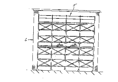
FIG. 1 illustrates a generally schematic view of a conventional scaffold
system;
FIG. 2 illustrates a perspective view of a system according to the present
invention;
FIG. 3 illustrates a side view of the system of FIG. 2 with parts removed for
clarity;
FIG. 4 illustrates an enlarged side view of a tube and a stud of the system
shown in
FIG. 3;
0406914.06
CA 02255258 1998-12-03
FIG. 5 illustrates a partially sectioned side view of system members retained
on the
tube and stud shown in FIG. 4;
FIG. 6 illustrates an isometric view of one embodiment of an adapter according
to the
present invention;
FIG. 7 illustrates a side view of the adapter of FIG. 6 attached to the tube
and stud of
FIG. 4 shown in shadow;
FIG. 8 illustrates a top view of the adapter of FIG. 7;
FIG. 9 illustrates a front elevational view of system members being retained
by a stud
on a tube and a stud on a stud adapter according to the present invention;
FIG. 10 illustrates an isometric view similar to FIG. 6 showing another
embodiment of
the adapter of the present invention retaining system members shown in shadow;
FIG. 11 illustrates a partially sectioned side view of the embodiment of FIG.
10
attached to a tube and retained by a stud shown in shadow;
FIG. 12 illustrates an isometric view of another embodiment according to the
present
invention;
0406914.06 1
CA 02255258 1998-12-03
FIG. 13 illustrates a partially sectioned side view of the embodiment of FIG.
12
attached to a tube and a stud shown in shadow;
FIG. 14 illustrates a partial rear view of the embodiment of FIG. 13 taken
from 14-14;
FIG. 15 illustrates an enlarged side view of another embodiment of a stud of
the
present invention;
FIG. 15A illustrates a side view of another embodiment of the adapter of the
present
invention;
FIG. 16A illustrates a top view of another embodiment of the adapter of the
present
invention;
FIG 16B illustrates a front view of the embodiment of FIG. 16A;
FIG 17A illustrates a top view of another embodiment of the adapter of the
present
invention;
FIG 17B illustrates a front view of the embodiment of FIG. 17A; and
FIG 17C illustrates a side view of embodiment of FIG. 17A.
oaob9ia.oe 11
CA 02255258 1998-12-03
DESCRIPTION OF PREFERRED EMBODIMENTS
The present invention and the various features and advantageous details
thereof are
explained more fully with reference to the non-limiting embodiments described
in detail in
the following description.
Referring generally to the drawings, FIGS. 1-17C, it can be seen that the
present
invention relates to scaffolding or shoring systems. Referring specifically to
FIG. l, a
conventional system 5 is shown in use next to a building 6. As shown in FIG.
2, the system, 5
of the present invention is constructed of preferably round steel system
members 12, vertical
tubes 14, and horizontal tubes 16. Planks 17, preferably of wood, aluminum, or
fiberglass, rest
on the horizontal tubes 16 to provide support for workers or equipment, as
shown in FIG. 3.
Horizontal tubes 16 are preferably connected to vertical tubes 14 by welding.
The inventive attachment device 10 of the system 5 includes first stud 19 and
guard rail
stud adapter 15 as best shown in FIG. 7. As best seen in FIGS. 4 and 5, first
stud 19 preferably
is made of metal and protrudes from vertical tube 14. First stud 19 is
preferably connected to
tube 14 by welding. First stud 19 is preferably formed by a cold forming
process and then it is
cut to the required length before it is welded to tube 14. As best shown in
FIG. 2, stud 19 is
preferably located at predetermined locations 19a on the scaffolding system 5.
Guard rail stud
adapter 15 is preferably constructed from steel and comprised of a generally U-
shaped member
20 as shown in FIG. 6. Adapter 15 is primarily formed by a stamping or
punching operation.
0406914.06 12
CA 02255258 1998-12-03
As best shown in FIG. 6, the generally U-shaped member 20 has a base portion
22, an
extending first arm 24, and extending second arm 26. The arms 24, 26
preferably extend
outwardly from the base portion 22. Preferably, the arms 24, 26 have ends 28,
28a which have
cut-outs or recesses 30, 30a in a preferably arcuate or semicircular shape to
receive the round
tubes 14 of the system 5. FIG. 8 shows a top view of adapter 15 wherein recess
30 of first end
28 of arm 24 receives vertical tube 14. The recesses 30, 30a allow the U-
shaped member 20
hold the tube 14, thus increasing the stability of the member 20 and
preventing the member
from moving when a torque is applied.
Referring to FIG. 7, preferably protruding in a direction opposite of the
first arm 24 and
second arm 26 of the U-shaped member 20 is second stud 32. Second stud 32 is
preferably
constructed from metal and welded to base portion 22 of U-shaped member 20.
However, one
skilled in the art will realize that second stud 32 may be connected by some
other means, for
example, by threads as may be first stud 19.
First stud 19 preferably has a locking wing latch 60a which includes wing 62a
which fits
in a slot (not shown) as best shown in FIG. 5. Wing 62a has a hole 58a which
receives roll pin
64a. Roll pin 64a is received in hole 63a in stud 19. The diameter of hole 58a
in wing 62a is
preferably slightly larger than the diameter of roll pin 64a to allow locking
wing latch 60a to be
swingably connected to the stud 19. Second pin 96a may fit into generally
crescent-shaped
hole 94a to further secure wing 62a to the stud 19. The crescent-shape of hole
94a gives wing
62a a significant swinging range of motion.
0406914.06 13
CA 02255258 1998-12-03
A brace 68, or some other member 12 of the system 5 may be received by stud 19
and
retained on stud 19 by locking wing latch 60a as shown in FIGS. 5, 9 and 11. A
pair of crossed
braces 68 obstruct open spaces in system 5 to prevent accidents.
Second stud 32 may have a locking wing latch 60 of a similar structure
including a hole
63, a wing 62, a roll pin 64, a generally crescent shaped hole 94, a hole 58,
and a second pin 96
as shown in FIG. 7. Second stud 32 receives guard rail 66. The locking wing
latch 60 prevents
removal of guard rails 66 and other like members 12.
In the embodiment of the inventive adapter 15 shown in FIGS. 12 - 14, second
stud 32 is
first welded to generally square-shaped spacer 52 which is then preferably
welded to U-shaped
member 20. In this embodiment, U-shaped member 20 has hole 53 configured with
a slot 53a
for receiving wing 62 of first stud 19 as shown in FIGS. 13 and 14. Spacer 52
may have a
counter-bore 54 which also dimensioned and configured to receive first stud 19
as best shown in
FIG. 14.
Referring to the embodiment in FIGS. 12-14 a generally 1-shaped coupling
member 44
may be cut from a piece of sheet metal. Coupling member 44 has a first end 46
and a second
end 48 which may be connected by welding to first arm 24 and second arm 26,
respectively, of
generally U-shaped member 20 as best shown in the embodiments in FIGS. 12 and
13. The 1-
shaped coupling member 44 preferably has a hole 56 for receiving first stud
19. Alternatively,
oao6ma.ob 14
CA 02255258 1998-12-03
as shown in the embodiments in FIGS. 6-11, the coupling member 44 may also be
bent from the
same piece of metal as U-shaped member 20.
In the embodiments shown in FIGS. 6-11, guard rail stud adapter 15 has an
extension leg
70 preferably integral with arm 24 to provide further support and clearance
for adapter 15 in
relation to tubes 14. Leg 70 may be formed as part of arm 24 during stamping.
It may also be
welded or otherwise connected to arm 24 later.
As best shown in the embodiments of FIGS. 6 and 10, coupling member 44 may
connect only to arm 26 of the U-shaped member 20 at first end 46. In these
embodiments, leg
72 extends from second end 48 of coupling member 44 to form an L-shaped member
49.
As shown best in FIGS. 6 and 10, some embodiments of the adapter 15 have a
pair of feet
78 at the end of each leg 70, 72. The feet 78 also help adapter 15 better
embrace tubes 14, as
best shown in FIG. 8. This improved embrace adds additional support and
torsion prevention
for the adapter 15. In FIG. 10, feet 78 are more pronounced and cut with
additional metal stock
for added strength.
One preferred embodiment also includes gussets 92 formed on the inside of the
U-shaped
member 20 to provide further reinforcement of arms 24, 26 relative to the base
portion 22 as
best shown in FIGS. 6-8. Preferably, gussets 92 are formed on the inside of
the U-shaped
0406914.06 1 5
CA 02255258 1998-12-03
member 20 by a stamping process. This process also forms a divot of the outer
side of U-
shaped member 20.
Refernng to FIGS. 9 and 10, guard rails 66 and crossed braces 68 preferably
include
paddles 88, 80, respectively, at each end. Within the paddles 80, 88, are
holes 82, 84,
respectively, for receiving studs 19, 32 as best shown in FIG. 9.
In the embodiment shown in Figure 6, ribs 76 are formed in adapter 15 for
further
reinforcement of the U-shaped and 1-shaped members 20 and 44, respectively.
Preferably, the
ribs 76 extend in the same direction as second stud 32 and provide support for
base portion 22
and first arm 24 as shown. In order to ease manufacture, the ribs 76 may be
conveniently
formed, preferably by cutting and bending from the same slab of metal which
forms the 1-
shaped member 44.
In the embodiments shown in FIGS. 6-11, adapter 15 has a generally central
opening 90
to receive first stud 19. In these embodiments, the adapter 15 is largely cut,
stamped, and bent
from a single piece of metal to form U-shaped member 20, the legs 70, 72 and 1-
shaped member
44. These parts are generally joined at bends 86 as shown in FIG. 7.
Another embodiment is illustrated in FIG. 15A. This embodiment is shaped
similar to
the embodiment shown in FIG 13, in that the guard rail stud adapter 15 is
comprised of a U-
shaped member 20. The generally U-shaped member 20 has base portion 22 and
first arm 24
0406914.06 16
CA 02255258 1998-12-03
and second arm 26. Between first arm 24 and second arm 26 is coupling member
44. The ends
of the coupling member 44a and 44b are inserted into slots (not shown) in the
first and second
arms, 24, 26 respectively. Once the ends 44a and 44b are inserted through the
slots they are
bent over to retain the coupling member 44 to the U-shaped member 20. Coupling
member 44
has generally S-shaped bend and has a hole 56 to receive a first stud 19. A
second stud 32
protrudes from the U-shaped member 20 as shown. First stud 19, in addition to
receiving the
guard rail stud adapter 15 may receive other members such as cross braces (not
shown).
Similarly, the second stud 32 can receive system members such as guard rails
(not shown).
FIGS 16A and 16B show another alternative embodiment of the present invention.
The
guard rail stud adapter 15 shown in FIG. 16A has a generally U-shaped portion
20, and first arm
24 and second arm 26 extending from base portion 22. Second stud 32 extends
outwardly from
base portion 22 in a direction opposite the first arm 24 and the second arm
26. As shown in 16b
hole 56 is provided in coupling member 44 which is integral with base portion
22 to receive an
existing first stud (not shown). Arms 24, 26 and base portion 22 are
configured to receive a
vertical tube (not shown) of a standard scaffolding or shoring system. Arms
24, 26 snugly
retain vertical tube to prevent movement of stud adapter 15 when in use.
Another embodiment of the inventive stud adapter 15 is shown in FIGS. 17A -
17C. In
that embodiment, as best shown in FIG. 17A, generally U-shaped member 20 has
first arm 24
and second arm 26 extending from base portion 22 of guard rail stud adapter
15. Coupling
member 44 is integral with base portion 22 has a hole 56 as best shown in FIG.
17B for
0406914.06 1 7
CA 02255258 1998-12-03
receiving first stud 19 as best shown in FIG. 17C. As shown in FIG. 17B and
17C, second stud
32 protrudes from base portion 22. As shown in FIG. 17C, guard rail 66 and
braces 68 as well
as other members may be attached to the studs 19 and 32. As mentioned above,
the members
may be secured to suds 19, 32 by alternative means such as wing nuts 98 as
shown in FIG. 17C.
In one embodiment of a stud 32b as shown in FIG. 15, wing 62b of locking wing
latch
60b has a generally oval-shaped hole 94b connected with roll pin 64b. As shown
in FIG. 15,
wing 62b can only pivot in a downward direction due to the generally upwardly
sloping shape
of the end 63a of the wing 62b and the downwardly sloping shape of slot 65b in
stud 32b. Wing
62b can also slide up and down for ease of engagement and disengagement when
in use because
of the generally exaggerated dimensions of hole 94b. Gravity tends to pull the
wing 62b
downwardly thus automatically retaining a paddle because there is more
material and more
weight at second end 62c than at end 63a.
The locking wing latch 60, 60a, 60b of the present invention is designed to
allow ease of
detachment and reattachment of cross braces 68 or guard rails 66 by the user
of the system 5
especially in dangerous environments or hazardous environments high off the
ground.
However, other configurations are imaginable to secure the scaffolding members
66, 68 to studs
19 and 32. For example, these configurations are described in U.S. Patent Nos.
3,751,081;
4,111,579; 2,832,649; 3,867,043; 5,186,568; and 2,698,552 incorporated herein
by reference.
0406914.06 1 8
CA 02255258 1998-12-03
In operation as best shown in FIG. 7, one embodiment of the guard rail stud
adapter 15 is
first attached to system 5 by being placed over existing first stud 19 (in
shadow) which
protrudes from upright vertical tube 14 (also in shadow). As best shown in
FIGS. 9 and 1 l,
system members 12 such as crossed braces 68 are slid over existing first stud
19. Then the
guard rail stud adapter 15 is slid in place. The holes 82 in the paddles 80 of
crossed braces 68
and hole 90 of the adapter 15 are properly dimensioned and configured to
receive first stud 19
as best shown in FIG. 9. U-shaped member 20 is configured and dimensioned in
such a manner
to allow the cross braces 68 to be retained without interference. Preferably
on stud 19, locking
wing latch 60a then drops into position to retain the members to the guard
rail stud adapter 15.
In this manner, the guard rail stud adapter 15 and crossed braces 68 are
safely retained to
system 5. Alternatively, locking latch 60a may be moved by hand as is known in
the art.
Once the guard rail stud adapter 15 is in place, protruding second stud 32 may
be used to
retain guard rails 66 as best shown in FIGS. 9 and 11. Paddles 88 of guard
rail 66 have holes
84 dimensioned and configured for receiving second stud 32 of adapter 15. Once
second stud
32 is placed in hole 84 of paddle 88, wing 62 of locking wing latch 60 drops
downwardly to
retain paddles 88. In one embodiment, this is accomplished by moving locking
wing 62b
downwardly as best shown in FIG. 15. In another embodiment, best shown in FIG.
15A the
wing 62 can be moved either upwardly or downwardly.
Preferably, the embodiment of inventive guard rail stud adapter 15 shown in
FIG. 6 is
about 5 '/z inches from first end 28 to second end 28a. It measures about 1
3/4 inches along each
0406914.06 19
CA 02255258 1998-12-03
end 28, 28a. From the tip of first end 28 to the base 22 of U-shaped member
20, the guard rail
stud adapter 15 measures about 3 inches. From the tip of the second end 28a to
the connection
point of the 1-shaped member 44, the leg 72 measures about 13/4 inches. First
stud 19 and
second stud 32 measure about I'/4 inches. The diameter of the opening 90 and
hole 56 is about
17/32 inches.
In the embodiments shown in FIGS. 6 - 11, the distance between arms 24, 26 is
about 1'/2
inches. In the embodiment shown in FIGS. 12 through 14, the distance between
arms 24, 26
is about 5 inches. The diameter of the recess located at the ends 28, 28a of
the legs 70, 72
is about 1 23/32 inches. The guard rail stud adapter 15 is preferably stamped
from a single
piece of plate steel about ~/s of an inch thick. The embodiments of FIGS. 1 SA-
17C are similarly
dimensioned.
Although the disclosed embodiments show gussets 92 and ribs 76 as structures
for
performing the function of strengthening the adapter 15, the structure for
strengthening can
be any other structure capable of strengthening the adapter 15, including, by
way of example,
a weldment or some other suitable structure.
Although the best mode contemplated by the inventors of carrying out the
present
invention is disclosed above, practice of the present invention is not limited
thereto. It will
be manifest that various other additions, modifications and rearrangements of
the features of
oaob9~a.o6 20
CA 02255258 1998-12-03
the present invention may be made without deviating from the spirit and scope
of the
underlying inventive concept.
For example, the adapter of the present invention can be made of any suitable
rigid
material. However, for the preferred stamping manufacturing operation
mentioned above, it
is an advantage to employ a metal material. Similarly, although metal or steel
is preferred
for the stud any material could be used in its place. In addition, other
individual components
need not be fabricated from the disclosed materials, but could be fabricated
from virtually
any suitable material.
Moreover, the individual components need not be formed in the disclosed
shapes, or
assembled in the disclosed configuration, but could be provided in virtually
any shape, and
assembled in virtually any configuration. Further, although the adapter
described herein is a
physically separate module, it will be manifest that the adapter may be
integrated into the
guard rail or cross brace with which it is associated. Furthermore, all the
disclosed features
of each disclosed embodiment can be combined with, or substituted for, the
disclosed
features of every other disclosed embodiment except where such features are
mutually
exclusive.
It is intended that the appended claims cover all such additions,
modifications and
rearrangements.
0406914.06 21