Language selection

Search

Patent 2255269 Summary

Third-party information liability

Some of the information on this Web page has been provided by external sources. The Government of Canada is not responsible for the accuracy, reliability or currency of the information supplied by external sources. Users wishing to rely upon this information should consult directly with the source of the information. Content provided by external sources is not subject to official languages, privacy and accessibility requirements.

Claims and Abstract availability

Any discrepancies in the text and image of the Claims and Abstract are due to differing posting times. Text of the Claims and Abstract are posted:

  • At the time the application is open to public inspection;
  • At the time of issue of the patent (grant).
(12) Patent Application: (11) CA 2255269
(54) English Title: IMPROVEMENTS IN GLAZED ROOFS
(54) French Title: AMELIORATIONS APPORTEES AUX TOITS ENDUITS DE VERNIS
Status: Deemed Abandoned and Beyond the Period of Reinstatement - Pending Response to Notice of Disregarded Communication
Bibliographic Data
(51) International Patent Classification (IPC):
  • E04D 03/08 (2006.01)
  • E04B 01/70 (2006.01)
  • E04D 03/06 (2006.01)
  • E04D 03/16 (2006.01)
  • E04D 13/16 (2006.01)
  • E04D 13/17 (2006.01)
(72) Inventors :
  • RICHARDSON, CHRISTOPHER (United Kingdom)
(73) Owners :
  • ULTRAFRAME (UK) LIMITED
(71) Applicants :
  • ULTRAFRAME (UK) LIMITED (United Kingdom)
(74) Agent: MARKS & CLERK
(74) Associate agent:
(45) Issued:
(22) Filed Date: 1998-12-02
(41) Open to Public Inspection: 1999-12-05
Examination requested: 2003-11-28
Availability of licence: N/A
Dedicated to the Public: N/A
(25) Language of filing: English

Patent Cooperation Treaty (PCT): No

(30) Application Priority Data:
Application No. Country/Territory Date
9812010.8 (United Kingdom) 1998-06-05

Abstracts

English Abstract


A glazed roof has a ridge and at least one free ridge end, a ventilation path
being
provided through a ridge end component.


Claims

Note: Claims are shown in the official language in which they were submitted.

5
CLAIMS
1. A glazed roof having a ridge and at least one free ridge end, a ventilation
path being
provided through a ridge end component.
2. A glazed roof as claimed in claim 1, wherein a generally vertical
ventilation tube is
provided at the ridge end.
3. A glazed roof as claimed in claim 2, wherein a finial or other decorative
cover fitted
over the ventilation tube leaving a space between edges thereof through which
air can
escape.
4. A glazed roof as claimed in claim 1, wherein the ridge end comprises a
flange
component of or mounted to a ridge beam end, the flange component being
arranged to
have ends of glazing bars connected thereto.
5. A glazed roof as claimed in claim 4, wherein a ventilation tube is mounted
through
the flange component.
6. A glazed roof as claimed in claim 5, wherein the tube and flange are a
single
component.
7. A glazed roof as claimed in claim 2, wherein a cover for the roof ridge end
has an
aperture therethrough for the ventilation tube.
8. A glazed roof as claimed in claim 7, wherein the ridge end cover is shaped
to sit on
the ventilation top.
9. A glazed roof as claimed in claim 7, wherein the aperture has a generally
central
slot connected by webs to sides of the aperture, the slot being arranged to
receive a spigot

6
or the like of a decorative component whereby the decorative component sits on
top of the
ventilation tube but has its bottom edge spaced from the cover to provide an
air passageway
therebetween.
10. A glazed roof as claimed in 2, wherein beneath the roof ridge end a cover
panel is
provided.
11. A glazed roof as claimed in claim 2, wherein the cover panel has an
aperture into or
over which the ventilation tube sits.
12. A glazed roof as claimed in claim 7, wherein over the aperture there is
provided a
hit and miss ventilator.
13. A glazed roof as claimed in claim 12, wherein the aperture is covered by a
radially
slotted cover with an associated rotatable slotted disc, whereby the disc can
be rotated
between a first position wherein respective slots of the cover and disc are
aligned to allow
air passage and a second passage wherein solid parts of the disc align with
slots of the
aperture to prevent air passage.
14. A glazed roof as claimed in claim 2, further comprising means for forced
ventilation.
15. A glazed roof as claimed in claim 14 further comprising an electrically
operated fan
within the ventilation tube to draw air through it from the conservatory.

Description

Note: Descriptions are shown in the official language in which they were submitted.


CA 02255269 1999-OS-17
~RO'IE~VTS IN GLAZED ROOFS
This invention concerns improvements in glazed roofs.
The invention is particularly concerned with conservatory roofs and, more
particularly, with means for ventilating conservatories. Conservatories are a
popular
addition to houses to pro~ride additional room with the attractions of being
light and
providing wide outwards viiews. Because conservatories are glazed extensively,
there can
be disadvantages, in that, when the weather is hot the conservatory interior
can become
very hot and when the weather is cold, the glazing is not able to retain heat.
As a
consequence of the latter condensation can form on inner surfaces of a
conservatory.
To combat these problems it is desirable to provide ventilation. One simple
form of
ventilation is to provide air passageways through the roof ridge of a
conservatory, so that
air can flow through the conservatory.
The ridge ventilation system does provide a large area over which rain ingress
is
possible i.e. along both sides of the ridge, where rain can splash upwards
from roof glazing
panels under a ridge cover and into the ridge beam. Therefore, rain baffles
and other
suitable seals have to be provided to prevent rain ingress into the
conservatory itself.
An object of this invention is to provide an alternative ventilation system
for a
glazed roof structure.
According to this invention it is proposed that, for a glazed roof having a
ridge and
at least one free ridge end, a ventilation path be provided through a ridge
end component.
Typically a Victorian or Edwardian style conservatory will have one or more
ridge
ends suitable for adoption oi-'the present invention. At such a ridge end
glazing bars extend

CA 02255269 1999-OS-17
2
downwardly and radially, a cover sits over the ridge end and a decorative
finial is mounted
on the cover. In a preferred form of the invention it is proposed that a
generally vertical
ventilation tube be provided at the ridge end. Then a finial or other
decorative cover may
be fitted over the ventilation tube leaving a space between edges thereof
through which air
can escape.
A preferred form ~~f ridge end for a glazed roof according to the invention
comprises a flange component of or mounted to a ridge beam end, the 'flange
component
being arranged to have ends of glazing bars connected thereto. The ventilation
tube is
preferably mounted through the flange component. In fact, the tube and flange
could be
made as a single component, such as a die cast component.
A cover for the roof ridge end preferably has an aperture therethrough for the
ventilation tube and is preferably shaped to sit on the ventilation tube top.
The aperture
preferably has a generally central slot connected by webs to sides of the
aperture, the slot
being arranged to receive a spigot or the like of a decorative component, such
as a finial,
whereby the decorative component ;sits on top of the ventilation tube but has
its bottom
edge spaced from the cover 1;o provide an air passageway therebetween.
Beneath the roof ridge end a cover panel is preferably provided. The cover
panel
preferably has an aperture into or over which the ventilation sits. Over the
aperture there is
preferably provided a hit and miss ventilator. Preferably the aperture is
covered by a
radially slotted cover with an associated rotatable slotted disc, whereby the
disc can be
rotated between a first position wherein respective slots of the cover and
disc are aligned to
allow air passage and a second position wherein solid parts of the disc align
with slots of
the aperture to prevent air passage.

CA 02255269 1999-OS-17
3
The ventilation system of tlhe invention may be used for natural ventilation.
In
other words when the ventilation passages are open warm air within a
conservatory will rise
and escape through the ventilation system. On the other hand forced
ventilation may be
possible with the ventilation system of the invention by providing an
electrically operated
fan or rotor within the ventilation tube to draw air through it from the
conservatory.
The invention will now be further described, by way of example only, with
reference to the accompanying drawings, in which:
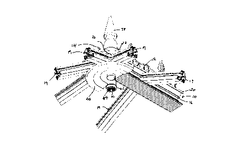
Figure 1 is a partially exploded view from below of a conservatory ridge end
with a
ventilation system;
Figure 2 is a further exploded view from below of the conservatory ridge of
Figure
1;
Figure 3 is a partially exploded view from above of the conservatory ridge end
of
Figure 1;
Figure 4 is a further explodf;d view from above of the conservatory ridge and
of
Figure l; and
Figure 5 is a section through the conservatory ridge end of Figure 1.
Referring to the accompanying drawings, the ridge end illustrated is typical
of a so-
called Victorian conservatory which has a ridge 10 with a decorative cresting
12 and a ridge
end generally designated 14 from which glazing bars 19 extend radially and
support glazing
panels (not shown) therebet<veen.
The conservatory roof ridge end comprises a ridge beam 16 having a generally
semi-circular ridge end plate 18 fixed thereto. The ridge end plate 18 slopes
downwardly
and has the glazing bars 19 attached thereto.

CA 02255269 1999-OS-17
4
Over the ridge bearn 16 is a capping 20 and at the ridge end is a generally
semi-
circular capping 22. Extending through the ridge end plate 18 is a ventilation
tube 24. The
plate 18 and tube 24 may be; made as a one-piece die cast item. Space between
ends of the
glazing bars 19 and the ventilation tube 24 is sealed with foamed plastics
material 26.
At its top the ventilation tube 24 extends through a circular aperture 28 in
the
capping 22. In the aperture 22 is a tube 30 with a closed bottom end connected
by webs 32
to sides of the aperture 28. The tube 30 receives a spigot 34 from base 36 of
finial 38, such
that there is an air space between the bottom edge of the base 36 and the
capping 22.
Beneath the ridge end is a cover plate 40. The cover plate has an aperture 42
into
which the bottom end of tb~e ventilation tube 24 extends. Covering the
aperture 42 is a
ventilation grille 44 having a plurality of radial slots 46. Rotatably mounted
above the
grille 44 is a disc 48 itself having a plurality of radial slots, whereby
alignment of the slots
of the cover and of the disc 1>ermit air passage into and through the
ventilation tube 24.
The ventilation tube 24 may be provided with an electrically operated fan or
rotor to
provide forced ventilation through tlse ventilation tube. Otherwise
ventilation occurs by
warmer air within the conservatory rising and passing through the ventilation
tube.

Representative Drawing
A single figure which represents the drawing illustrating the invention.
Administrative Status

2024-08-01:As part of the Next Generation Patents (NGP) transition, the Canadian Patents Database (CPD) now contains a more detailed Event History, which replicates the Event Log of our new back-office solution.

Please note that "Inactive:" events refers to events no longer in use in our new back-office solution.

For a clearer understanding of the status of the application/patent presented on this page, the site Disclaimer , as well as the definitions for Patent , Event History , Maintenance Fee  and Payment History  should be consulted.

Event History

Description Date
Application Not Reinstated by Deadline 2007-12-03
Time Limit for Reversal Expired 2007-12-03
Deemed Abandoned - Failure to Respond to Maintenance Fee Notice 2006-12-04
Amendment Received - Voluntary Amendment 2006-07-06
Inactive: IPC from MCD 2006-03-12
Inactive: S.30(2) Rules - Examiner requisition 2006-01-06
Amendment Received - Voluntary Amendment 2004-11-19
Letter Sent 2003-12-09
All Requirements for Examination Determined Compliant 2003-11-28
Request for Examination Received 2003-11-28
Request for Examination Requirements Determined Compliant 2003-11-28
Inactive: Cover page published 1999-12-05
Application Published (Open to Public Inspection) 1999-12-05
Letter Sent 1999-06-08
Inactive: Single transfer 1999-05-17
Inactive: Correspondence - Formalities 1999-05-17
Inactive: First IPC assigned 1999-01-27
Classification Modified 1999-01-27
Inactive: IPC assigned 1999-01-27
Inactive: Filing certificate - No RFE (English) 1999-01-12
Application Received - Regular National 1999-01-12

Abandonment History

Abandonment Date Reason Reinstatement Date
2006-12-04

Maintenance Fee

The last payment was received on 2005-12-01

Note : If the full payment has not been received on or before the date indicated, a further fee may be required which may be one of the following

  • the reinstatement fee;
  • the late payment fee; or
  • additional fee to reverse deemed expiry.

Patent fees are adjusted on the 1st of January every year. The amounts above are the current amounts if received by December 31 of the current year.
Please refer to the CIPO Patent Fees web page to see all current fee amounts.

Fee History

Fee Type Anniversary Year Due Date Paid Date
Registration of a document 1998-12-02
Application fee - standard 1998-12-02
MF (application, 2nd anniv.) - standard 02 2000-12-04 2000-11-23
MF (application, 3rd anniv.) - standard 03 2001-12-03 2001-11-29
MF (application, 4th anniv.) - standard 04 2002-12-02 2002-11-27
MF (application, 5th anniv.) - standard 05 2003-12-02 2003-11-27
Request for examination - standard 2003-11-28
MF (application, 6th anniv.) - standard 06 2004-12-02 2004-11-24
MF (application, 7th anniv.) - standard 07 2005-12-02 2005-12-01
Owners on Record

Note: Records showing the ownership history in alphabetical order.

Current Owners on Record
ULTRAFRAME (UK) LIMITED
Past Owners on Record
CHRISTOPHER RICHARDSON
Past Owners that do not appear in the "Owners on Record" listing will appear in other documentation within the application.
Documents

To view selected files, please enter reCAPTCHA code :


To view images, click a link in the Document Description column. To download the documents, select one or more checkboxes in the first column and then click the "Download Selected in PDF format (Zip Archive)" or the "Download Selected as Single PDF" button.

List of published and non-published patent-specific documents on the CPD .

If you have any difficulty accessing content, you can call the Client Service Centre at 1-866-997-1936 or send them an e-mail at CIPO Client Service Centre.


Document
Description 
Date
(yyyy-mm-dd) 
Number of pages   Size of Image (KB) 
Representative drawing 1999-11-22 1 17
Abstract 1998-12-01 1 6
Description 1998-12-01 4 148
Claims 1998-12-01 2 57
Drawings 1998-12-01 5 197
Abstract 1999-05-16 1 5
Claims 1999-05-16 2 59
Description 1999-05-16 4 155
Drawings 1999-05-16 5 177
Description 2006-07-05 4 145
Claims 2006-07-05 2 44
Filing Certificate (English) 1999-01-11 1 163
Courtesy - Certificate of registration (related document(s)) 1999-06-07 1 116
Reminder of maintenance fee due 2000-08-02 1 109
Reminder - Request for Examination 2003-08-04 1 112
Acknowledgement of Request for Examination 2003-12-08 1 188
Courtesy - Abandonment Letter (Maintenance Fee) 2007-01-28 1 176
Correspondence 1999-01-18 1 34
Correspondence 1999-05-16 13 431
Fees 2005-11-30 1 50