Note: Descriptions are shown in the official language in which they were submitted.
CA 022~270 1998-12-02
RAIL CAR TRUCK DAMPING SYSTEM
THE FIELD OF THE INVENTION
The present invention relates to darnping systems for rail cars and more
specifically to damping systems for what is known in the art as a "three-piece truck." Such a
truck has a bolster riding on two side frames and the damping system is used to restrain
5 relative movement between the bolster and the side frames. Ln such damping systems the
bolster has pockets which face the column wear surfaces of the side frame and there is a
friction wedge positioned in each pocket. The wedge is spring-loaded to bear against a
slanted wall of the bolster pocket and against the column wear plate of the side frame.
The forces acting upon such trucks during normal rail car use will cause
10 relative lateral movement between the bolster and the side frame and in the past such
movement has been restrained not only by the friction wedge, but also by what are known as
gibs which are outwardly-exten~ling projections on the bolster located on each side of the side
frame column. The present invention elimin~tes the necessity of such gibs and provides for
lateral restraint between the bolster and side frame in the form of a vertical extension on the
15 side frame column wear plate which extends into an aligned recess on the friction wedge,
with the recess being formed between spaced friction wedge surfaces which face the side
frame column wear plate.
Similarly, the forces acting upon the rail car truck will cause lateral movement
between the friction wedge and the bolster pocket, with such movement at times causing
20 damage to the sides of the bolster pocket. The present invention is also directed to
restraining friction wedge movement within the bolster pocket by the use of an extension on
. _
CA 022~270 1998-12-02
the bolster pocket wear plate, which extension fits within a recess between spaced surfaces
on the friction wedge which are in contact with the bolster pocket wear plate.
As can be seen, a rail car damping system can include both of the above
features or either one or the other. The restraints on relative movement between the bolster
5 and the side frame may be provided in the described manner, but the same friction wedge
may not have the described restraint between the wedge and the bolster pocket side walls.
Similarly, a wedge may be restrained against lateral movement in the bolster pocket and not
use the described restrain to limit lateral movement between the bolster and the side frame.
SUMl\/IARY OF THE INVENTION
The present invention relates to rail car damping systems and more specifically
to such damping systems which provide for lateral restraint between the bolster and the side
frame and restrained movement of the friction wedge within the bolster pocket.
Another purpose of the invention is to provide a bolster/pocket friction wedge
construction in which there is restraint, provided by a bolster pocket extension, to lateral
movement of the friction wedge within the bolster pocket.
Another purpose is a rail car damping system in which the side frame column
wear plate has a vertical extension which fits within a recess between spaced friction wedge
surfaces, which extension limits bolster/side frame relative movement.
Other purposes will appear in the ensuing specification, drawings and claims.
BRIEF DESCRIPTION OF THE DRAWINGS
The invention is illustrated diagr~mm~tic~lly in the following drawings
wherein:
Fig. 1 is a partial side view, in part section, illustrating the bolster side frame
CA 022~270 1998-12-02
friction wedge relationship;
Fig. 2 is a front view of the bolster pocket wear plate;
Fig. 3 is a side view of the bolster pocket wear plate;
Fig. 4 is a top view of the bolster pocket wear plate;
Fig. 5 is a partial top view of the bolster and side frame of Fig. 1;
Fig. 6 is a front view of the side fraIne column wear plate extension;
Fig. 7 is a top view of the friction wedge, and
Fig. 8 is a section along plane 8-8 of Fig. 7.
D ES Cl~lEYrIO N O F T H E P R EFE~URE D E M B O DI~IE N T
The present invention will describe a rail car damping system which may
utilize a friction wedge of the type illustrated in U.S. Patents 5,511,489 and 5,555,818, both
owned by Standard Car Truck Company of Park Ridge, Illinois, the assignee of the present
application. The disclosure of these two patents is herein incorporated by reference.
The '489 and '818 patents show what is described as a dual face friction
wedge. A friction wedge has two spaced friction surfaces. One opposes the slanted wall of
the bolster pocket and the other opposes the column wear plate of the side frame. In the
reference patents both of these surfaces are formed by spaced, generally parallel, planar
friction faces. In other words, the area of friction-contact between the wedge and both the
bolster and the side frame have been separated into two spaced surfaces, specifically for the
reasons stated in greater detail in those patents. The present invention utilizes the recess
formed between the spaced friction surfaces to provide restraints on side frame/bolster lateral
movement and/or wedge/bolster pocket lateral movement. The invention will be described in
.. ... , ... . . .. , , _
CA 022~270 1998-12-02
connection with a rail car truck in which both of these concepts are present. It should be
understood that in some applications there may be only restraint to side frame/bolster relative
movement, whereas, in other applications there may be only restraint to wedge movement
within the bolster pocket.
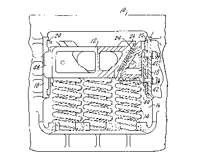
In Fig. 1, a side frame is indicated at 10 and a bolster 12 is supported on
springs 14 within a window 16 of the side frame. As indicated above, there will be two side
frames and one bolster in a three-piece truck, with the side frames being supported on the
truck wheelsets. The side frame has spaced columns 18, one on either side of the window
16. Each of these columns carries a wear plate 20. The wear plates 20 face pockets 22
0 formed at the end of the bolster. What has been described thus far is a conventional three-
piece rail car truck damping system with the friction wedge to be described damping relative
movement between the side frame and bolster. The bolster pocket 22 has a slanted face 24
and attached to this slanted face 24 is a wear plate indicated at 26 and shown specifically in
Figs. 2, 3 and 4.
The friction wedge is indicated at 28 and there will be one positioned in each
bolster pocket 22. The friction wedge 28 has a pair of spaced planar surfaces 30 with a
recess 32 formed therebetween and the faces 30 will be in contact with the bolster pocket
wear plate 26. The wear plate 26 has a generally centrally located extension or rib indicated
at 34 which is preferably welded to the wear plate. The rib 34 has a width such that the rib
0 may be positioned within the recess 32 and will only permit a very limited degree of lateral
movement between the wedge 28 and the pocket 22. This protects the walls 36 of the bolster
pocket, a location which has been known to evidence substantial wear during normal rail car
CA 022~270 1998-12-02
operation. Contact between the wedge and the bolster pocket wall tends to wear the wall,
requiring either that this surface be built up through welding or that the bolster itself be
replaced. By restraining lateral movement between the friction wedge and the bolster pocket,
such contact can be avoided and the dimensions of the rib 34 and the recess 32 are such as to
S permit a limited degree of lateral movement, but yet not sufficient lateral movement to allow
for contact between the sides of the wedge and the bolster pocket sides 36.
The column wear plate 20 will have a generally centrally located column track
40, shown in Fig. 6, which column track will be ~tt~rhed by bolts 42 to the side frame
column wear plate 20. Focusing particularly on Fig. 7, there is a recess 44 between the
0 spaced planar wear surfaces 46 of the friction wedge 28. The surfaces 46 will bear against
the column wear plate, as particularly shown in Fig. 5, providing frictional resistance to
relative vertical and lateral movement between the bolster and the side frame. The column
track 40 has a width relative to the width of the recess 44 to permit a degree of lateral
movement between the wedge and bolster and the side frame, but not such lateral movement
as to permit contact between the side frame and the gibs 48 located on the bolster at each
side of the side frame. The gibs 48 are used in a truck of this design to limit side frame
bolster relative lateral movement. However, the gibs are a point of wear on the bolster and
must be replaced after a certain length of service time. The gap or space 50 between each
gib 48 and the adjacent portion of the side frame is greater than the difference in width
'0 between the column track 40 and the recess 44. Thus, the colulnn track will prevent contact
between the side frame and the gibs 48. In some applications, the gibs may even be
elimin~t~d.
CA 022=,=,270 1998-12-02
The bolster pocket has a recess 52 on each side thereof which will
accommodate a wing 54 on each side of the wedge. The wings will prevent relative pivotal
movement between bolster and side frame from causing undesired contact between the bolster
and side frame in the area adjacent the bolster pocket.
Since the column track 40 may itself be subject to wear by contact between
this member and the sides of the recess 44, column track 40 will be bolted to the column
wear plate 20 for ease in replacement.
The invention is particularly designed to prevent wear at two locations on a
conventional three-piece rail car truck which in the past has required taking the truck out of
service for periodic maintenance. Specifically, the gibs 48 tend to wear because of excessive
side frame/bolster contact. The use of the column track which will limit such movement has
the clear advantage of elimin~ting or reducing gib wear.
Similarly, the use of the rib 34 on the bolster pocket wear plate 26 which
extends into a recess in the slanted wall facing surfaces of the friction wedge restricts lateral
movement of the wedge within the bolster pocket, thus eli",i"~ g wear to the sides of the
bolster pocket.
Whereas the preferred form of the invention has been shown and described
herein, it should be realized that there may be many modifications, substitutions and
alterations thereto.
'O