Language selection

Search

Patent 2255339 Summary

Third-party information liability

Some of the information on this Web page has been provided by external sources. The Government of Canada is not responsible for the accuracy, reliability or currency of the information supplied by external sources. Users wishing to rely upon this information should consult directly with the source of the information. Content provided by external sources is not subject to official languages, privacy and accessibility requirements.

Claims and Abstract availability

Any discrepancies in the text and image of the Claims and Abstract are due to differing posting times. Text of the Claims and Abstract are posted:

  • At the time the application is open to public inspection;
  • At the time of issue of the patent (grant).
(12) Patent Application: (11) CA 2255339
(54) English Title: BEVERAGE DISPENSING APPARATUS
(54) French Title: DISTRIBUTEUR DE BOISSONS
Status: Deemed Abandoned and Beyond the Period of Reinstatement - Pending Response to Notice of Disregarded Communication
Bibliographic Data
(51) International Patent Classification (IPC):
  • B67D 07/80 (2010.01)
  • B67D 01/00 (2006.01)
  • B67D 01/02 (2006.01)
  • B67D 01/06 (2006.01)
  • B67D 01/08 (2006.01)
(72) Inventors :
  • BUCHANAN, BRENT (Canada)
(73) Owners :
  • NEAT BREWING IDEAS INC.
(71) Applicants :
  • NEAT BREWING IDEAS INC. (Canada)
(74) Agent: OSLER, HOSKIN & HARCOURT LLP
(74) Associate agent:
(45) Issued:
(22) Filed Date: 1998-12-10
(41) Open to Public Inspection: 2000-06-10
Examination requested: 1998-12-10
Availability of licence: N/A
Dedicated to the Public: N/A
(25) Language of filing: English

Patent Cooperation Treaty (PCT): No

(30) Application Priority Data: None

Abstracts

English Abstract


A beverage dispensing apparatus consists of a housing incorporating a heat
exchanger for cooling the housing, with a housing having a suitable interior
configuration for housing one or more beverage canisters. One or more beverage
dispensing taps are mounted to the exterior of the housing. Gas delivery
conduits
permit the delivery of a pressuring gas from an external gas source, into the
beverage
canisters within the interior of the housing for pressurizing the canisters.
Pressurizing
gas may both carbonate the beverage and provide sufficient pressure for
delivery of the
beverage through the taps.


Claims

Note: Claims are shown in the official language in which they were submitted.

THE EMBODIMENTS OF THE INVENTION IN WHICH AN EXCLUSIVE
PROPERTY OR PRIVILEGE IS CLAIMED ARE DEFINED AS FOLLOWS:
1. A beverage dispensing apparatus, comprising:
a housing having an interior volume suitable for retaining at least one
beverage
canisters, and a sealable door opening suitable for removal and replacement of
said
canisters;
a beverage dispensing tap mounted to said housing;
a source of pressurizing gas; and
conduits suitable for delivering said pressurizing gas to said canisters, and
for
delivering a beverage from said canister to said beverage tap.
2. Apparatus as defined in claim 1, wherein said housing is generally
rectangular,
and said entry portal comprises a front-opening door.
3. Apparatus as defined in claim 2, wherein said at least said beverage tap is
mounted to said door.
4. Apparatus as defined in claim 1, wherein said cooling means are integral
with
said housing.
5. Apparatus as defined in claim 1, wherein said source of pressurizing gas
comprises a gas cylinder external to said housing; and an inlet opening into
said
housing for receiving said pressurizing gas from said external pressurizing
gas source,
said inlet being associated with at least one flexible conduit within the
interior of said
housing for delivering said pressurizing gas from said inlet to said at least
one beverage
canisters.
6. Apparatus as defined in claim 1, wherein said source of pressurizing gas
comprises a gas cylinder housed within said housing.

7. Apparatus as defined in claim 1, further comprising at least one well
recessed
into the floor of said housing for receiving said at least one beverage
cannister.

Description

Note: Descriptions are shown in the official language in which they were submitted.


CA 02255339 1998-12-10
-1-
BEVERAGE DISPENSING APPARATUS
Field of the Invention
The present invention relates to a refrigerated beverage dispensing apparatus.
The apparatus includes a refrigerated housing for retaining one or more
pressurized
beverage-filled canisters, with the housing incorporating beverage taps for
dispensing
the beverages.
Background of the Invention
Beverage dispensing devices are well-known for use in restaurants and bars, as
well as for home use. Typically, such devices include a beverage canister,
pressurizing
means for pressurizing the canisters and a tap for dispensing the pressurized
beverage.
Preferably, cooling means are provided to dispense the beverage in chilled
form. The
pressurizing means may conveniently comprise a gas cylinder for discharging
the
beverage canisters. The external gas cylinder conveniently discharges CO~ into
the
beverage canister, for carbonating the beverage.
By way of example, U.S. Patent No. 5,303,845 (Osawa) discloses a beverage
dispensing system whereby an external gas cylinder charges one or more
beverage
canisters, which in turn supply carbonated, pressurized beverage to a tap. An
external
cooling means cools the beverage subsequent to its discharge from the canister
and
prior to entering the tap. Similarly, U.S. Patent No. 5,115,942 (Merrill et
al.),
discloses an external C02 for charging a beverage canister, with an external
cooling
means for cooling the beverage between the canister and a remote beverage tap.
The increasing popularity of in-home preparation of wine and beer, amongst
other beverages, has created a need for a relatively simple beverage cooling
and
dispensing device, whereby beverage canisters may be charged with a
pressurizing gas
such as C02 cylinder, chilled and dispensed. It is desirable to provide a
relatively
compact unit that is suitable for in-home use, and that does not rely on a
separate

CA 02255339 1998-12-10
-2-
cooling mechanism for cooling the beverage immediately prior to dispensing
from the
tap.
Obiects of the Invention
Accordingly, it is an object of the present invention to provide an improved
beverage dispensing apparatus, wherein a single housing encloses one or more
pressurizable beverage containers and a cooling mechanism, with beverage taps
mounted to the exterior of the housing.
It is a further object to provide an improved and simplified beverage
dispensing
apparatus suitable for in-home use, and particularly suitable for dispensing
of bulk
carbonated beverages such as beer and soft drinks, as well as non-carbonated
beverages.
Summary of the Invention
In light of the foregoing objects, the present invention comprises in one
aspect
a beverage dispensing apparatus comprising a housing for retaining one or more
beverage canisters;
refrigeration means for cooling the interior of the housing to a temperature
suitable for dispensing of cooled beverages;
a source of pressurized gas;
a conduit for transmitting pressurized gas from said pressurized gas source
into
the interior of one or more of the canisters;
valve means associated with said conduit for regulating the pressure of said
gas; and
one or more beverage taps located on the exterior of the housing, and having
conduits connecting said taps with the beverage canisters whereby pressurized
beverage is dispensed from the canisters by way of the taps.
Conveniently, the housing has a front-opening door, and the taps are located
on

CA 02255339 1998-12-10
-3-
the door.
The pressurized gas source may comprise in one version a gas cannister
external to the housing, and in another version a cannister housed within the
interior of
the housing.
Preferably, the gas conduit connecting the gas inlet to the canisters
comprises
conventional flexible gas hosing. The conduit connecting the beverage taps to
the
containers conveniently comprises food-grade flexible hosing.
The invention will now be described by way of specific embodiments, including
reference to the following illustrations:
Brief Description of the Drawings
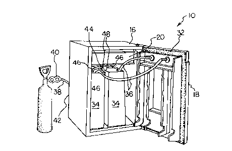
Figure 1 is a perspective view of the present apparatus in the open position,
showing the interior of the housing;
Figure 2 is a perspective view of the present apparatus in the closed
position;
Figure 3 is a view as in Figure 1, with the internal canisters removed;
Figure 4 is a rear elevational view; and
Figure 5 is a perspective view, from the front, of a second embodiment of the
invention.
Detailed Description of the Preferred Embodiments
Refernng to Figures 1 - 4, a first embodiment of the present apparatus is
denoted globally by reference number 10. The apparatus comprises a housing 16
generally similar to a conventional refiigerator, having a front-opening pivot
mounted
door 18 for access to the interior. An enclosed conventional refi-igeration
mechanism
20 within the interior of the housing maintains the interior at a selected
cool
temperature. The housing rests on slideable or rolling canisters 22. The
exterior face
24 of the door features one or more beverage taps 26 for dispensing of cooled

CA 02255339 1998-12-10
-4-
beverages. A stainless steel or molded plastic drip tray 30 is positioned
conveniently
below the taps.
A beveled molded seal 32 is disposed around the perimeter of the door to seal
the door against the entry of outside air or moisture.
The interior of the housing is sized to conveniently retain two five-gallon
sealed
stainless steel beverage canisters 34. The beverage canisters 34 are each
operatively
linked to an associated tap by means of a flexible hose 36.
The beverage dispensers are each pressurized by a charging gas such as C02,
which conveniently both carbonates the beverage and pressurizes the beverage
sufficiently for dispensing. An external gas cylinder comprises a source for
the
charging gas, and is linked to the housing by means of a gas conduit 3 8. A
pressure
regulator 40 controls the gas pressure at a selected level. The gas conduit is
operatively connected to an inlet 42 at the rear of the housing. Within the
housing, the
inlet enters a line sputter 44 for directing the gas to multiple gas hoses 46,
each of
which feeds a corresponding canister. The line splitter is associated with
valves 48 for
controlling the gas flow to a selected hose or hoses in the event only a
single canister is
housed within the device.
A molded plastic base 60 within the interior of the housing 16 contains a pair
of
wells 62 (seen more particularly in Figure 3) for receiving and supporting the
canisters
34. A second fitting comprising a capping member 64 incorporates a pair of
similar
circular recesses 66 for placement over the taps of the canisters.
In use, the user fills one or more canister with a selected beverage, and
connects to the cannister the gas hose and the beverage outlet hose. Once the
canisters have been appropriately connected, they are placed within the
housing and
the housing door is closed. The regulator is then adjusted to deliver a
selected gas

CA 02255339 1998-12-10
-5-
pressure, and sufl'lcient time is permitted to elapse for the beverage to
cool.
A second embodiment of the apparatus 79 is illustrated in Figure 5. In this
version, the charging cylinder 80 is housed within an interior compartment 82
within
the housing 16. The pressure regulator, beverage cannisters and connecting
hoses (not
shown) are arranged essentially in the same manner as the first embodiment.
Although the present invention has been described by way of a preferred
embodiment, it will be seen that numerous departs from and variations of this
described embodiment may be made by one skilled in the art to which the
invention
pertains, without departing from the spirit and scope of the claims within
this
specification.

Representative Drawing
A single figure which represents the drawing illustrating the invention.
Administrative Status

2024-08-01:As part of the Next Generation Patents (NGP) transition, the Canadian Patents Database (CPD) now contains a more detailed Event History, which replicates the Event Log of our new back-office solution.

Please note that "Inactive:" events refers to events no longer in use in our new back-office solution.

For a clearer understanding of the status of the application/patent presented on this page, the site Disclaimer , as well as the definitions for Patent , Event History , Maintenance Fee  and Payment History  should be consulted.

Event History

Description Date
Inactive: Agents merged 2013-10-24
Inactive: IPC deactivated 2011-07-29
Inactive: First IPC derived 2010-02-01
Inactive: IPC from MCD 2010-02-01
Inactive: First IPC derived 2010-01-30
Inactive: IPC expired 2010-01-01
Inactive: IPC from MCD 2006-03-12
Application Not Reinstated by Deadline 2003-03-26
Inactive: Dead - No reply to s.30(2) Rules requisition 2003-03-26
Deemed Abandoned - Failure to Respond to Maintenance Fee Notice 2002-12-10
Inactive: Abandoned - No reply to s.30(2) Rules requisition 2002-03-26
Inactive: S.30(2) Rules - Examiner requisition 2001-09-26
Application Published (Open to Public Inspection) 2000-06-10
Inactive: Cover page published 2000-06-09
Inactive: Correspondence - Formalities 1999-07-08
Inactive: Single transfer 1999-03-10
Inactive: First IPC assigned 1999-01-29
Classification Modified 1999-01-29
Inactive: IPC assigned 1999-01-29
Inactive: Filing certificate - RFE (English) 1999-01-13
Application Received - Regular National 1999-01-13
Request for Examination Requirements Determined Compliant 1998-12-10
All Requirements for Examination Determined Compliant 1998-12-10

Abandonment History

Abandonment Date Reason Reinstatement Date
2002-12-10

Maintenance Fee

The last payment was received on 2001-12-06

Note : If the full payment has not been received on or before the date indicated, a further fee may be required which may be one of the following

  • the reinstatement fee;
  • the late payment fee; or
  • additional fee to reverse deemed expiry.

Patent fees are adjusted on the 1st of January every year. The amounts above are the current amounts if received by December 31 of the current year.
Please refer to the CIPO Patent Fees web page to see all current fee amounts.

Fee History

Fee Type Anniversary Year Due Date Paid Date
Application fee - small 1998-12-10
Request for examination - small 1998-12-10
Registration of a document 1999-03-10
MF (application, 2nd anniv.) - small 02 2000-12-11 2000-12-08
MF (application, 3rd anniv.) - small 03 2001-12-10 2001-12-06
Owners on Record

Note: Records showing the ownership history in alphabetical order.

Current Owners on Record
NEAT BREWING IDEAS INC.
Past Owners on Record
BRENT BUCHANAN
Past Owners that do not appear in the "Owners on Record" listing will appear in other documentation within the application.
Documents

To view selected files, please enter reCAPTCHA code :


To view images, click a link in the Document Description column. To download the documents, select one or more checkboxes in the first column and then click the "Download Selected in PDF format (Zip Archive)" or the "Download Selected as Single PDF" button.

List of published and non-published patent-specific documents on the CPD .

If you have any difficulty accessing content, you can call the Client Service Centre at 1-866-997-1936 or send them an e-mail at CIPO Client Service Centre.


Document
Description 
Date
(yyyy-mm-dd) 
Number of pages   Size of Image (KB) 
Representative drawing 2000-06-04 1 13
Abstract 1998-12-09 1 18
Description 1998-12-09 5 197
Drawings 1998-12-09 4 74
Claims 1998-12-09 2 46
Drawings 1999-07-07 3 54
Filing Certificate (English) 1999-01-12 1 163
Courtesy - Certificate of registration (related document(s)) 1999-04-25 1 117
Reminder of maintenance fee due 2000-08-13 1 109
Courtesy - Abandonment Letter (R30(2)) 2002-06-03 1 172
Courtesy - Abandonment Letter (Maintenance Fee) 2003-01-06 1 176
Correspondence 1999-01-18 1 23
Correspondence 1999-07-07 4 92
Fees 2000-12-07 1 54
Fees 2001-12-05 1 60