Language selection

Search

Patent 2255343 Summary

Third-party information liability

Some of the information on this Web page has been provided by external sources. The Government of Canada is not responsible for the accuracy, reliability or currency of the information supplied by external sources. Users wishing to rely upon this information should consult directly with the source of the information. Content provided by external sources is not subject to official languages, privacy and accessibility requirements.

Claims and Abstract availability

Any discrepancies in the text and image of the Claims and Abstract are due to differing posting times. Text of the Claims and Abstract are posted:

  • At the time the application is open to public inspection;
  • At the time of issue of the patent (grant).
(12) Patent: (11) CA 2255343
(54) English Title: MODULAR VACUUM THERMAL PROCESSING INSTALLATION
(54) French Title: INSTALLATION MODULAIRE DE TRAITEMENT SOUS VIDE THERMIQUE
Status: Expired and beyond the Period of Reversal
Bibliographic Data
(51) International Patent Classification (IPC):
  • C21D 01/773 (2006.01)
  • C21D 01/74 (2006.01)
  • C21D 09/00 (2006.01)
  • F27B 09/02 (2006.01)
  • F27B 09/04 (2006.01)
  • F27B 09/20 (2006.01)
  • F27B 17/00 (2006.01)
(72) Inventors :
  • PELISSIER, LAURENT (France)
(73) Owners :
  • ETUDES ET CONSTRUCTIONS MECANIQUES
(71) Applicants :
  • ETUDES ET CONSTRUCTIONS MECANIQUES (France)
(74) Agent: NORTON ROSE FULBRIGHT CANADA LLP/S.E.N.C.R.L., S.R.L.
(74) Associate agent:
(45) Issued: 2006-10-17
(22) Filed Date: 1998-12-01
(41) Open to Public Inspection: 1999-06-02
Examination requested: 2003-05-23
Availability of licence: N/A
Dedicated to the Public: N/A
(25) Language of filing: English

Patent Cooperation Treaty (PCT): No

(30) Application Priority Data:
Application No. Country/Territory Date
97/15506 (France) 1997-12-02

Abstracts

English Abstract

The present invention relates to a chained thermal processing installation under rarefied atmosphere including several processing cells linked in a horizontal plane to a common air-tight chamber provided with handling means for transferring a load from one cell to another. The common chamber is a cylinder with a horizontal axis, at least one end of which is arranged to receive a module in the form of a cylindrical extension to which additional cells are connected.


French Abstract

La présente invention concerne une installation de traitement thermique à la chaîne, sous atmosphère raréfiée, comprenant plusieurs cellules de traitement reliées dans un plan horizontal à une enceinte hermétique commune, munie de moyens d'acheminement permettant de transférer une charge d'une cellule à une autre. L'enceinte commune est un cylindre avec un axe horizontal, dont au moins une extrémité peut accueillir un module sous la forme d'une rallonge cylindrique à laquelle des cellules supplémentaires sont connectées.

Claims

Note: Claims are shown in the official language in which they were submitted.

7
The embodiments of the invention in which an exclusive
property or privilege is claimed are defined as follows:
1. A chained thermal processing installation under
rarefied atmosphere including several processing cells (14, 15,
16) linked in a horizontal plane to a common air-tight chamber
provided with handling means (18, 22) for transferring a load
(24) from one cell to another, wherein the common chamber is a
cylinder with a horizontal axis (10), at least one end of which
is arranged to receive a module (8) in the form of a cylindrical
extension (10') to which additional cells (14') are connected.
2. The thermal processing installation of claim 1,
wherein at least one end of the cylinder is provided with a
removable cover (12) in place of which the module can be mounted
(8).
3. The thermal processing installation of claim 1,
wherein the handling means include a carriage (18) moving in a
direction parallel to the cylinder axis (10) and servicing the
cells by means of a telescopic element (22).
4. The thermal processing installation of claim 1,
wherein one of the cells is an oil quenching cell (30) also used
as a loading/unloading cell.
5. The thermal processing installation of claim 1,
wherein the carriage (18) moves on rails (20) attached to the
chamber (10), these rails being prolonged in the module (8) by
rails (20') attached to the module.
6. The thermal processing installation of claim 1,
wherein the module (8) is provided to be assembled by one end to
the chamber (10) and by the other end to another module.
7. The thermal processing installation of claim 2,
wherein the module (8) is open at both ends, the end which
remains open after assembly of the module to the chamber (10)
receiving an additional module or the cover (12).
8. The thermal processing installation of claim 1,
including a gas quenching cell (16) operating with nitrogen or a
mixture comprising at least 50% of nitrogen.

Description

Note: Descriptions are shown in the official language in which they were submitted.


CA 02255343 1998-12-O1
MODULAR VACUC1M THERMAL PROCESSING INSTALLATION
BACK~~iOUND OF THE INVENTION
Field of the Invention
The present invention relates to a thermal processing
installation under rarefied atmosphere including several process-
ing cells linked to a common air-tight chamber provided with
handling means for transferring a load from one cell to another.
Discussion of the Related Art
French patent application 2537260 describes such a
thermal processing installation. The processing cells are
arranged horizontally in a stellate fashion inside a cylindrical
air-tight chamber having a vertical axis. The cells are serviced
by a central handling device.
A disadvantage of known installations of this type is
that the number of processing cel:Ls is fixed. There is no possi-
bility of modifying the installation to make it have additional
processing cells.
Another disadvantage of such installations is that it
is particularly difficult to achieve maintenance operations
inside the chamber, for example to adjust the handling device.
Such an operation most often requires a complete or partial
disassembly of the handling device.

CA 02255343 1998-12-O1
2
S~urcnary of the invention
An object of the present invention is to provide a
chained thermal processing installation under rarefied atmosphere
which can receive any number of processing cells.
Another object of the present invention is to provide
such an installation which enables particularly easy maintenance
operations inside the chamber.
These objects are achieved by means of a chained ther-
mal processing installation under rarefied atmosphere including
several processing cells linked in a horizontal plane to a common
air-tight chamber provided with handling means for transferring a
load from one cell to another. The common chamber is a cylinder
with a horizontal axis, at least one end of which is arranged to
receive a module in the form of a cylindrical extension to which
additional cells are connected.
According to an embodiment of the present invention, at
least one end of the cylinder is provided with a removable cover
in place of which the module can be mounted.
According to an embodiment of the present invention,
the handling means include a carriage moving in a direction
parallel to the cylinder axis and servicing the cells by means of
a telescopic element.
According to an embodiment of the present invention,
one of the cells is an oil quenching cell also used as a load-
ing/unloading cell.
According to an embodiment of the present invention,
the carriage moves on rails attached to the chamber, these rails
being prolonged in the module by rails attached to the module.
According to an embodiment of the present invention,
the module is provided to be assembled by one end to the chamber
and by the other end to another module.
According to an embodiment of the present invention,
the module is open at both ends, the end which remains open after
assembly of the module to the chamber receiving an additional
module or the cover.

CA 02255343 1998-12-O1
3
According to an embodiment of the present invention,
the installation includes a gas quenching cell operating with
nitrogen or a mixture comprising at least 50~ of nitrogen.
The foregoing objects, features and advantages of the
present invention will be discussed in detail in the following
non-limiting description of specific embodiments in connection
with the accompanying drawings.
Brief Description of the Drawings
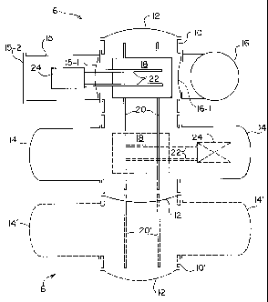
Fig. 1 schematically shows a top view of a chained
thermal processing installation according to the present inven
tion;
Fig. 2 very schematically shows a side cross-section
view of the installation of Fig. l; and
Fig. 3 shows a side cross-section view of an alterna-
tive of the installation of Fig, 1.
Detailed Description
To be able to use any number of processing cells in a
chained thermal processing installation, the present invention
provides a modular installation. The modularity is made possible
by a specific structure of the installation.
Fig. 1 illustrates a basic module 6 of an installation
according to the present invention and in dotted lines an
additional module 8.
Basic module 6 includes an air-tight chamber 10 in the
form of a cylinder of horizontal axis. Both ends of cylinder 10,
provided with flanges, are closed by removable air-tight covers
12. The processing cells are laterally connected to cylinder 10
and are located in a same horizontal plane. As an example, Fig. 1
illustrates two thermal processing cells 14 arranged facing each
other, a loading/unloading cell 15, and a gas quenching cell 16
arranged facing the loading/unloading cell 15.
As can be better seen in Fig. 2, cylindrical chamber 10
includes lateral cylindrical extensions 10-1 provided with
flanges enabling the tight attachment of the processing cells,
for example, by means of bolts.

CA 02255343 1998-12-O1
4
Conventionally, the openings for communication of ther-
mal processing cells 14 with chamber 10 are provided with doors
(not shown) which are heat insulating but not air-tight. Indeed,
the pressure which is created in chamber 10, on the order of 5
millibars, is that which must be present in processing cells 14.
Conversely, loading/unloading cell 15 and gas quenching cell 16
are provided with air-tight doors, respectively 15-1 and 16-1, at
their openings for communication with chamber 10. Indeed,
loading/unloading cell 15 includes an outer door 15-2 for insert-
ing the loads to be processed into the installation. It must thus
be possible to submit cell 15 to the atmospheric pressure without
disturbing the atmosphere of chamber 10. Similarly, a pressure
higher than the atmospheric pressure is present in cell 16 during
quenching operations.
A handling device is in the form of a carriage 18
moving in a direction parallel to the axis of cylinder 10.
Carriage 18 moves, for example, on rails 20 extending along the
entire length of cylinder 10. Carriage 18 is provided with a
telescopic fork 22 which can extend on either side of carriage 18
to the centers of cells 14 to 16 to pick up and deposit a load
being processed.
In Fig. 1, carriage 18 is located at the level of cells
15 and 16, and telescopic fork 22 penetrates into cell 15 to pick
up a load 24. Of course, cell 15 has previously been submitted to
the pressure of chamber 10 to allow door 15-1 to open. As shown
in Fig. 2, load 24 is laid on supports 26 elevating load 24 with
respect to the bottom of the cell and enabling fork 22 to pass
under the load. Fork 22 is raised to lift up load 24 from
supports 26, then drawn back to bring load 24 onto carriage 18.
Then, carriage 18 moves in front of the desired cell, for
example, to the position shown in dotted lines. Fork 22 is then
drawn out and lowered to deposit load 24 in the cell.
In the basic installation of Fig. 1 (shown in full
line), the two cells 14 are, for example, carburizing cells,
which will enable the processing of two loads 24 practically at

CA 02255343 1998-12-O1
the same time. The single quenching cell 16 will suffice since
the quenching operation is particularly fast as compared to
carburizing operations.
If the yield of the installation should be increased or
5 if it is desired to perform other processings, additional
processing cells are required. In this case, a module 8 shown in
dotted lines in Fig. 1 is assembled to the basic installation.
Module 8 includes a cylindrical portion 10' which is assembled in
the continuity of cylindrical chamber 10 in place of one of
covers 12. The removed cover 12 may be used to close the free end
of cylindrical portion 10'. Module 8 may be comprised, as shown,
of only two additional cells 14' connected facing each other to
cylindrical portion 10'.
Of course, additional modules may be assembled to the
free ends of module 8 and basic module 6 in place of covers 12.
Several modules may thus be assembled in cascade to create a
thermal processing installation adapted to the user's needs.
In the case where carriage 18 is mounted on rails 20,
as shown, module 8 may include rails 20' which connect to rails
20 when module 8 is assembled to the basic installation.
To operate in chamber 1.0 or 10', it is sufficient to
remove one or both covers 12, which opens a corridor enabling a
person to penetrate into the installation and to easily perform
the necessary operations on handling device 18, 22, and on the
cells. In case of need, the handling device is moved to one side
or the other of the chamber.
As shown in Fig. 2, the installation may include a
loading/unloading cell 15 and a gas quenching cell 16. A gas
quenching is appropriate for a great number of materials. To
obtain the right compromise between the power required to stir
the hardening gas and the variety of the materials which can be
gas-quenched, nitrogen or a mixture containing at least 500 of
nitrogen is used.
Nevertheless, some materials require an oil quenching.

CA 02255343 1998-12-O1
6
Fig. 3 shows a side cross-section view of an instal-
lation of the type of Fig. 1, comprising an oil quenching cell
30. Cell 30 may advantageously replace loading/unloading cell 15
of Figs. 1 and 2. Oil quenching cell 30 then comprises an outer
door 30-1 used to extract and introduce loads 24 in the
installation. Cell 30 further includes an elevator 32 enabling
maintaining the load at a height adapted to handling device 18,
22 and to immerge load 24 in an oil bath 34.
This disposition is advantageous because, since the
quenching operation is the last one, the processed load 24 may
directly be extracted, which cancels the time of travel from a
quenching cell to the loading/unloading cell. The additional cost
of a dedicated loading/unloading cell is also avoided.
Of course, oil quenching cell 30 is provided, like
loading/unloading cell 15, with an air-tight door (not shown)
meant to isolate it from chamber 10 to enable loading/unloading
operations at atmospheric pressure without affecting the pressure
present in chamber 10.
Handling device 18, 22 i.s driven by conventional means.
2 0 For example, carriage 18 may move along rails 20 by means of an
integrated electric motor provided with a pinion which is in mesh
with a rack arranged in a direction parallel to the rails.
Telescopic fork 22 may be extended and retracted by a chain or
lever system. The raising and lowering of the fork may be
obtained by a cam or eccentric system.
Of course, the present invention is likely to have
various alterations, modifications, and improvements which will
readily occur to those skilled in the art. Such alterations,
modifications, and improvements a:re intended to be part of this
disclosure, and are intended to be within the spirit and the
scope of the present invention. Accordingly, the foregoing
description is by way of example only and is not intended to be
limiting. The present invention is limited only as defined in the
following claims and the equivalents thereto.

Representative Drawing
A single figure which represents the drawing illustrating the invention.
Administrative Status

2024-08-01:As part of the Next Generation Patents (NGP) transition, the Canadian Patents Database (CPD) now contains a more detailed Event History, which replicates the Event Log of our new back-office solution.

Please note that "Inactive:" events refers to events no longer in use in our new back-office solution.

For a clearer understanding of the status of the application/patent presented on this page, the site Disclaimer , as well as the definitions for Patent , Event History , Maintenance Fee  and Payment History  should be consulted.

Event History

Description Date
Time Limit for Reversal Expired 2013-12-03
Letter Sent 2012-12-03
Inactive: Late MF processed 2009-01-12
Letter Sent 2008-12-01
Grant by Issuance 2006-10-17
Inactive: Cover page published 2006-10-16
Inactive: Office letter 2006-09-21
Inactive: Corrective payment - s.78.6 Act 2006-08-23
Pre-grant 2006-08-01
Inactive: Final fee received 2006-08-01
Letter Sent 2006-05-18
Inactive: Correspondence - Transfer 2006-03-20
Inactive: IPC from MCD 2006-03-12
Notice of Allowance is Issued 2006-02-24
Letter Sent 2006-02-24
Notice of Allowance is Issued 2006-02-24
Inactive: Approved for allowance (AFA) 2005-11-29
Inactive: IPC assigned 2005-09-07
Inactive: IPC assigned 2005-09-06
Letter Sent 2003-07-02
Request for Examination Requirements Determined Compliant 2003-05-23
All Requirements for Examination Determined Compliant 2003-05-23
Request for Examination Received 2003-05-23
Inactive: Entity size changed 2001-12-06
Inactive: Inventor deleted 1999-10-01
Inactive: Correspondence - Formalities 1999-10-01
Letter Sent 1999-10-01
Inactive: Filing certificate - No RFE (English) 1999-10-01
Inactive: Correspondence - Formalities 1999-09-30
Inactive: Correspondence - Formalities 1999-08-31
Inactive: Single transfer 1999-08-31
Inactive: Cover page published 1999-06-03
Application Published (Open to Public Inspection) 1999-06-02
Classification Modified 1999-01-28
Inactive: First IPC assigned 1999-01-28
Inactive: IPC assigned 1999-01-28
Inactive: Courtesy letter - Evidence 1999-01-19
Inactive: Filing certificate - No RFE (English) 1999-01-14
Application Received - Regular National 1999-01-13

Abandonment History

There is no abandonment history.

Maintenance Fee

The last payment was received on 2005-11-22

Note : If the full payment has not been received on or before the date indicated, a further fee may be required which may be one of the following

  • the reinstatement fee;
  • the late payment fee; or
  • additional fee to reverse deemed expiry.

Patent fees are adjusted on the 1st of January every year. The amounts above are the current amounts if received by December 31 of the current year.
Please refer to the CIPO Patent Fees web page to see all current fee amounts.

Owners on Record

Note: Records showing the ownership history in alphabetical order.

Current Owners on Record
ETUDES ET CONSTRUCTIONS MECANIQUES
Past Owners on Record
LAURENT PELISSIER
Past Owners that do not appear in the "Owners on Record" listing will appear in other documentation within the application.
Documents

To view selected files, please enter reCAPTCHA code :


To view images, click a link in the Document Description column (Temporarily unavailable). To download the documents, select one or more checkboxes in the first column and then click the "Download Selected in PDF format (Zip Archive)" or the "Download Selected as Single PDF" button.

List of published and non-published patent-specific documents on the CPD .

If you have any difficulty accessing content, you can call the Client Service Centre at 1-866-997-1936 or send them an e-mail at CIPO Client Service Centre.

({010=All Documents, 020=As Filed, 030=As Open to Public Inspection, 040=At Issuance, 050=Examination, 060=Incoming Correspondence, 070=Miscellaneous, 080=Outgoing Correspondence, 090=Payment})


Document
Description 
Date
(yyyy-mm-dd) 
Number of pages   Size of Image (KB) 
Representative drawing 1999-06-02 1 7
Description 1998-11-30 6 279
Abstract 1998-11-30 1 16
Claims 1998-11-30 1 48
Drawings 1998-11-30 2 31
Representative drawing 2006-09-19 1 8
Filing Certificate (English) 1999-01-13 1 163
Courtesy - Certificate of registration (related document(s)) 1999-09-30 1 140
Filing Certificate (English) 1999-09-30 1 175
Reminder of maintenance fee due 2000-08-01 1 109
Acknowledgement of Request for Examination 2003-07-01 1 173
Commissioner's Notice - Application Found Allowable 2006-02-23 1 162
Maintenance Fee Notice 2009-01-11 1 171
Late Payment Acknowledgement 2009-02-02 1 164
Maintenance Fee Notice 2013-01-13 1 170
Correspondence 1999-01-18 1 32
Correspondence 1999-08-30 4 138
Correspondence 1999-09-29 3 84
Correspondence 1999-09-30 3 81
Correspondence 2006-02-01 1 17
Correspondence 2006-07-31 1 35
Correspondence 2006-09-20 1 20
Fees 2009-01-11 2 66