Language selection

Search

Patent 2255365 Summary

Third-party information liability

Some of the information on this Web page has been provided by external sources. The Government of Canada is not responsible for the accuracy, reliability or currency of the information supplied by external sources. Users wishing to rely upon this information should consult directly with the source of the information. Content provided by external sources is not subject to official languages, privacy and accessibility requirements.

Claims and Abstract availability

Any discrepancies in the text and image of the Claims and Abstract are due to differing posting times. Text of the Claims and Abstract are posted:

  • At the time the application is open to public inspection;
  • At the time of issue of the patent (grant).
(12) Patent: (11) CA 2255365
(54) English Title: COMMINUTING APPARATUS
(54) French Title: APPAREIL DE COMMINUTION
Status: Deemed expired
Bibliographic Data
(51) International Patent Classification (IPC):
  • B02C 13/20 (2006.01)
  • B02C 18/14 (2006.01)
  • B02C 18/18 (2006.01)
  • B27L 11/00 (2006.01)
(72) Inventors :
  • KOTTMANN, NORBERT (Germany)
(73) Owners :
  • EUREC TECHNOLOGY GMBH (Germany (Democratic Republic))
(71) Applicants :
  • KOTTMANN, NORBERT (Germany)
(74) Agent: FETHERSTONHAUGH & CO.
(74) Associate agent:
(45) Issued: 2004-05-25
(22) Filed Date: 1998-12-09
(41) Open to Public Inspection: 2000-04-21
Examination requested: 1999-12-09
Availability of licence: N/A
(25) Language of filing: English

Patent Cooperation Treaty (PCT): No

(30) Application Priority Data:
Application No. Country/Territory Date
198 47 886 0 Germany 1998-10-21

Abstracts

English Abstract


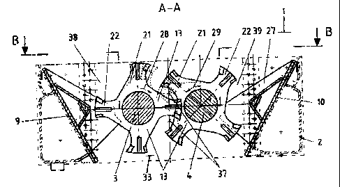
A comminuting apparatus has a housing and a crushing area. The
housing includes left and right bearing plates, left and right reinforcing,
bearing
and holdback plates, each with clearing and crushing prongs. The crushing unit
includes left and right crushing shafts which are rotationally supported by
the
housing are interconnected to rotate in opposite directions, synchronously.
Each
crushing shaft includes a number of radially-extending tool carries having
tool
heads which carry clearing devices and front and rear wear inserts, in seats
within the tool heads. The crushing unit can be configured to provide clearing
spacing between adjacent clearing devices of adjacent tool carriers, or to
provide
an overlap thereof. The clearing and crushing prongs are arranged between
each of the tool carriers. An intermediate crushing area is formed between the
left anti right crushing shafts. The tool carriers can include relatively high
and
low tool heads to provide differing peripheral rates of rotation for the tools
which define inner and outer spheres of actions.


Claims

Note: Claims are shown in the official language in which they were submitted.


I Claim:

1. A comminuting apparatus comprising a housing and a crushing
area, the housing including a left bearing plate, a right bearing plate, a
left
reinforcing, bearing and holdback plate with clearing and crushing prongs and
a right reinforcing, bearing and holdback plate with clearing and crushing
prongs and comprising a left crushing shaft and a right crushing shaft, each
rotationally supported by the housing, each crushing shaft including a number
of tool carriers having tool heads which have clearing devices in clearing
seats,
front wear inserts in front wear insert seats and rear wear inserts in rear
wear
insert seats.
2. Comminuting apparatus according to claim 1, wherein the left
crushing shaft is equipped with tool carriers and the right crushing shaft
with
tool carriers.
3. Comminuting apparatus according to claim 1, wherein a tool
carrier has tool heads whereby the number of tool heads also determine the
grain size of the output.
4. Comminuting apparatus according to claim 1, wherein a
clearing and crushing prong is arranged between each of the tool carriers in
the
left crushing area.
5. Comminuting apparatus according to claim 1, wherein a
clearing and crushing prong is arranged between each of the tool carriers in
the
right crushing area.


7


6. Comminuting apparatus according to claim 1, wherein an
intermediate crushing area, formed by the left crushing shaft and the right
crushing shaft, is located in the crushing area, the left crushing shaft
crushes in
the operating direction of rotation and the right crushing shaft crushes in
the
opposite direction of rotation and both shafts move synchronously in opposite
direction.
7. Comminuting apparatus according to claim 1, wherein an
intermediate crushing area, formed by the left crushing shaft and the right
crushing shaft, is located in the crushing area, the left crushing shaft
crushes in
the operating direction of rotation and the right crushing shaft crushes in
the
opposite direction of rotation, a clearing spacing is formed between the
clearing devices of the left crushing shaft and the clearing devices of the
right
crushing shaft and both shafts move synchronously in opposite direction.
8. Comminuting apparatus according to claim 1, wherein a left
crushing area is formed in the crushing area and the left crushing area
comprises the left crushing shaft with tool carriers and clearing devices and
crushers, with the left bearing plate, the left reinforcing, bearing and
holdback
plate as well as the left clearing and crushing prongs, whereby the clearing
and
crushing prongs extend between the tool carriers.
9. Comminuting apparatus according to claim 1, wherein a right
crushing area is formed in the crushing area and the right crushing area
comprises the right crushing shaft with toot carriers and clearing devices and
crushers, with the right bearing plate, the right reinforcing, bearing and
holdback plate as well as the right clearing and crushing prongs, whereby the
clearing and crushing prongs extend between the tool carriers.


8


10. Comminuting apparatus according to claim 1, wherein the
width of the clearing and crushing prongs is variable and that, with a low
number of tool carriers per crushing shaft, with an operating direction of
rotation of the shafts in opposite directions in the left and right crushing
area, a
different grain size of the output is obtained than in the intermediate
crushing
area, that is that the grain size and throughput capacity are determined by
the
selection of the operational direction of rotation of the crushing shafts.
11. Comminuting apparatus according to claim 1, wherein the
clearing angle is less or greater than 0°.
12. Comminuting apparatus according to claim 1, wherein clearing
devices consist of an impact-resistant material.
13. Comminuting apparatus according to claim 1, wherein the
clearing device is fastened to the tool carrier by welding, screwing or
pinning.
14. Comminuting apparatus according to claim 1, wherein the
front wear insert and the rear wear insert consist of an impact-resistant
material.
15. Comminuting apparatus according to claim 1, wherein the tool
carrier has a high tool head and one or more low tool heads.
16. Comminuting apparatus according to claim 1, wherein the tool
carrier can have one or more high tool heads and one or more low tool heads in
any order desired.


9


17. Comminuting apparatus according to claim 16, wherein the low
tool heads and the high tool heads of the tool carrier create inner and outer
spheres of action, respectively, when the tool carrier is rotating.
18. Comminuting apparatus according to claim 17, wherein the
clearing devices fastened in the high tool heads are positioned within the
outer
sphere of action and wherein the clearing devices fastened in the low tool
heads are positioned within the inner sphere of action.
19. Comminuting apparatus according to claim 1, wherein the
difference between an inside active diameter and an outside active diameter is
greater than 1 millimeter thereby providing desirable tearing behaviour due to
the varying peripheral speed of the tool heads.
20. Comminuting apparatus according to claim 1, wherein the
rotational speed of the left crushing shaft and the right crushing shaft is
between 0 and 60 revolutions/minute.
21. Comminuting apparatus according to claim 1, wherein the
throughput of the crushing unit can be regulated according to the desired
throughput quantity by means of the variable speed.
22. Comminuting apparatus according to claim 1, wherein the
crushing burr is determined by the speed selection.

Description

Note: Descriptions are shown in the official language in which they were submitted.


CA 02255365 2000-O1-20
1208-002PCA
Comminuting Apparatus
Field of the invention
The invention concerns a comminuting apparatus for wood, refuse and
other r? eakable, tearable or workable waste.
Background
Slowly running crushing devices or crushing plants with 2 parallel tool
shafts that have disk-like tool carriers with mounted or installed crushing
tools,
are known from the prior art.
The crushing devices or crushing installations of this type have numerous
drawbacks, because they primarily crush or comminute the material in only one
operating direction of rotation of the crushing shafts and thus only in a
single
working range and, especially during the crushing of refuse, are only cleared
from adhered materials during the reversal of rotation. A mode of operation of
this type results in that a relatively large amount of material becomes
compressed between the shafts which, in turn, negatively affects the feeding
characteristics of the crushing devices, reduces the throughput and negatively
affects the power input required for crushing the material.
Brief descri tion
The object of the invention is a crushing unit of the aforementioned type
that reduces and eliminates the disadvantages of the prior art, has a simple
structure and has a low technological demand and space requirement, whereby
the routine expenditures during practical use are low. The novel crushing unit
preferably has 3 crushing areas and can operate in either direction of
rotation of
the tool shafts during crushing or tearing or reduction of the volume during
1

CA 02255365 2000-O1-20
working of non-breakable or non-tearable materials. The novel crushing unit is
thus in the form of a reciprocating unit and is useful for various crushings.
More particularly, an ol;,iect of the invention is to provide a crushing unit
that
can optionally carry out two different methods of operation corresponding to
the
properties of the material to be crushed.
These objects are met by the present invention, wherein the
communicating apparatus has a housing and a crushing area therein, and
wherein the housing comains a left bearing plate, a right bearing plate, a
left
reinforcing, supporting and holdback plate with clearing and crushing prongs
and
a right reinforcing, supporting and holdback plate with clearing and crushing
prongs. The housing has a bearing area and a coupling area, the bearing area
has a support and a right bearing, and the coupling area has a left outer
coupling part and a right outer coupling part, both being attached to the
crushing shafts. The crushing unit has a left crushing shaft and a right
crushing
shaft, the left and right clearing and crushing prongs, whereby the left
crushing
shaft is accommodated by the left fixed bearing and has a left outer coupling
half that is accommodated by a left coupling pin, and the right crushing shaft
is
accommodated by the right fixed bearing, and has a right outer coupling half
that is accommodated by a right coupling pin, and tool carriers sit on the
crushing shafts and have tool heads that in turn have clearing devices in
clearing
seats, front wear inserts in front insert seats and rear wear inserts in rear
insert
seats.
Brief description of the drawing
The invention is described in greater detail with reference being had to
the attached drawing, in which:
Fig. 1 is a cross-sectional view of a complete arrangement of the
2

CA 02255365 2000-O1-20
comminuting apparatus of the present invention, in a front view
looking from the section A - A in Figure 2;
Fig. 2 is a plan view of the apparatus in the Cirection B - B in Figure l;
S
Fig. 3 is a schematic side elevation of a tool carrier;
Fig. 4 is a schematic front elevation of the tool carrier of Fig. 3;
Fig. 5 is a schematic front elevation of the tool carrier as an unfinished
part, in a front view,
Fig. 6 is a schematic detail of the complete tool carrier arrangment as a
detail X from Fig. 1; and
Fig. 7 is another plan view of the apparatus along the section B - B in
Figure 1, showing clearing spacings.
Detailed description of the invention
As shown in Figs. 1 - 4, the crushing unit 1 (or ~omminuting apparatus)
of the present includes left and right crushing shafts 3, 4 rotationally
supported
by a housing 2. The crushing shafts 3, 4 carry a number of tool carriers 13
(e.g., 3-10) which extend radially outwardly from the shafts 3, 4.
The shafts 3, 4 are interconnected to synchronously rotate in opposite
directions, and the crushing unit 1 is operable in two modes whereby in one
mode material is drawn between the two shafts, and in the other mode, material
is drawn between each shaft and the outside walls of the housing. The left and
right crushing shafts 3, 4 are rotationally supported by left and right fixed
3

CA 02255365 2000-O1-20
bearings 5, 6 and left and right coupling members 7, 8, which coupling members
are accommodated by left and right coupling pins 42, 43. The shafts 3, 4 are
interconnected to rotate in opposite directions as depicted in Fig. 1.
Preferably, the crushing unit 1 is operated such that the rotational rate of
the crushing shafts 3, 4 is between 0 and 60 revolutions per minute and most
suitably between 0 and 30 revolutions per minute. It can be appreciated that
the throughput of the crushing unit 1 (and the crushing burr) can be regulated
by adjusting the rotational rate of the shafts 3, 4.
Each tool carrier 13 includes a number of tool heads (21, 22) each of
which supports a front and rear wear insert 17, 18, and supports a clearing
device 15. As shown in Figs. 2 and 4, the clearing devices 15 are aligned
substantially perpendicular to the tool carriers 13 and extend outwardly from
the
tool carriers 13 in a direction substantially parallel to the longitudinal
axes of the
crushing shafts 3, 4.
As best seen in Fig. S, each heads 21, 22 of the tool carriers 13 includes
a clearing seat 16 for receiving a clearing tool 15, and front and rear wear
insert
seats 18, 19, for receiving the front and rear wear inserts, respectively.
The heads of the tool carriers 13 can have different radial heights such
that for example a relatively high tool 21 is followed, angularly by a
relatively
low tool head 22. The clearing devices 15 do not exceed the radial height of
the tool heads 21, 22 such that the low and high tool heads 21, 22 of a
rotating
tool carrier 13 create inner and outer spheres of action 30, 31, also
indicated as
inside and outside active diameters 40, 41. Preferably, the radial difference
between the inside and outside diameters 40, 41 is greater than 1 mm to
provide
a certain amount of variance in the peripheral speeds of high and low tool
4

CA 02255365 2000-O1-20
heads to provide desirable tearing to the work material.
As shown ir. Fig. 4, the clearing tool 13 preferably has a clearing bevel 26
on the radially outside surface thereof. The clearing bevel 26 preferably
forms
an angle which is nit equal to zero. The clearing devices can be comprised of
impact-resistant material ark can be fastened to the tool carrier by any
suitable
method such as welding, screwing or pinning. Also, the clearing devices 15
preferably do not have any knife-shaped or wedge-shaped formatters.
The housing 2 includes left and right bearing plates 9, 10, left and right
bearing and holdback plates 11, 12, and left and right clearing and crushing
prongs 27. The left and right bearing plates 9, 10 are inclined downwardly and
inwardly toward the crushing shafts 3, 4. The left and right clearing and
crushing prongs 27 extend inwardly from the bearing panels 9, 10 to between
adjacent tool carriers 13 and between the clearing devices 15 attached
thereto.
The left and right bearing and holdback plates extend inwardly from the left
and
right bearing plates 9, 10, between the clearing and crushing prongs 27.
The crushing unit 2 has a crushing area 33 which is divided into left and
right crushing areas 38, 39, and an intermediate crushing area 37. The
intermediate crushing area 37 is defined by the left and right crushing shafts
3,
4. Material is comminuted in the intermediate crushing area 37 when the
crushing unit 1 is operated in a first mode wherein the left and right shafts
3, 4
rotate in opposite, inward directions of rotation 28, 29 (as depicted in Fig.
1).
The left crushing area 38 is defined by the left crushing shafts and the
left bearing plate, left bearing and clearing plate 11 and the left clearing
and
crushing prongs 27. The right crushing area 39 is defined in a similar manner.
5

CA 02255365 2000-O1-20
Material is comminuted in the left and right crushing areas 38, 39 when
the crushing unit 1 is operated in a second mode wherein the left and right
shafts rotate in opposite outward directions ~~f rotation. (reverse of Fig.
1).
As shown in Fig. 1, the crushing unit 1 can be configured such that a
clearing space 46 exists between adjacent portions of clearing devices 15 of
adjacent tool carriers 13. Alternatively, as shown in Fig. 1, the crushing
unit 1
can be configured such that adjacent clearing devices 15 overlap.
As seen in Figs. 2 and 7, the tool carriers 13 of the left and right
crushing shafts 3, 4 are arranged in interleaved fashion such that the
clearance
between adjacent tool carriers 13 in the intermediate crushing area 37 is less
than the clearance between the tool carriers 13 and the adjacent clearing and
crushing prongs 27 in the left and right crushing areas 38, 39. Thus, it can
be
appreciated that the crushing unit 1 can be operated to produce different
comminution characteristics simply by operating the crushing unit 1 in one of
the
two modes of operation discussed above, without adjusting or changing the
configuration of any of the components of the crushing unit 1.
6

Representative Drawing
A single figure which represents the drawing illustrating the invention.
Administrative Status

For a clearer understanding of the status of the application/patent presented on this page, the site Disclaimer , as well as the definitions for Patent , Administrative Status , Maintenance Fee  and Payment History  should be consulted.

Administrative Status

Title Date
Forecasted Issue Date 2004-05-25
(22) Filed 1998-12-09
Examination Requested 1999-12-09
(41) Open to Public Inspection 2000-04-21
(45) Issued 2004-05-25
Deemed Expired 2012-12-10

Abandonment History

There is no abandonment history.

Payment History

Fee Type Anniversary Year Due Date Amount Paid Paid Date
Application Fee $150.00 1998-12-09
Request for Examination $200.00 1999-12-09
Maintenance Fee - Application - New Act 2 2000-12-11 $50.00 2000-11-02
Maintenance Fee - Application - New Act 3 2001-12-10 $50.00 2001-10-12
Maintenance Fee - Application - New Act 4 2002-12-09 $100.00 2002-11-05
Maintenance Fee - Application - New Act 5 2003-12-09 $150.00 2003-09-08
Registration of a document - section 124 $100.00 2003-12-01
Final Fee $300.00 2004-03-11
Maintenance Fee - Patent - New Act 6 2004-12-09 $200.00 2004-11-16
Maintenance Fee - Patent - New Act 7 2005-12-09 $200.00 2005-11-23
Maintenance Fee - Patent - New Act 8 2006-12-11 $200.00 2006-12-11
Maintenance Fee - Patent - New Act 9 2007-12-10 $400.00 2008-01-07
Maintenance Fee - Patent - New Act 10 2008-12-09 $250.00 2008-11-06
Maintenance Fee - Patent - New Act 11 2009-12-09 $250.00 2009-11-16
Maintenance Fee - Patent - New Act 12 2010-12-09 $250.00 2010-11-08
Owners on Record

Note: Records showing the ownership history in alphabetical order.

Current Owners on Record
EUREC TECHNOLOGY GMBH
Past Owners on Record
KOTTMANN, NORBERT
Past Owners that do not appear in the "Owners on Record" listing will appear in other documentation within the application.
Documents

To view selected files, please enter reCAPTCHA code :


To view images, click a link in the Document Description column. To download the documents, select one or more checkboxes in the first column and then click the "Download Selected in PDF format (Zip Archive)" or the "Download Selected as Single PDF" button.

List of published and non-published patent-specific documents on the CPD .

If you have any difficulty accessing content, you can call the Client Service Centre at 1-866-997-1936 or send them an e-mail at CIPO Client Service Centre.


Document
Description 
Date
(yyyy-mm-dd) 
Number of pages   Size of Image (KB) 
Representative Drawing 2000-04-13 1 17
Claims 2003-09-04 4 146
Drawings 2003-09-04 5 136
Cover Page 2000-04-13 1 29
Drawings 2000-01-20 5 142
Abstract 2000-01-20 1 29
Claims 2000-01-20 4 146
Description 2000-01-20 6 241
Cover Page 2000-10-30 1 45
Description 1998-12-09 4 116
Claims 1998-12-09 6 192
Drawings 1998-12-09 5 189
Representative Drawing 2004-04-22 1 19
Cover Page 2004-04-22 1 54
Correspondence 1999-01-19 1 29
Assignment 1998-12-09 3 113
Prosecution-Amendment 1999-12-09 1 29
Prosecution-Amendment 1999-12-09 2 66
Correspondence 2000-01-20 18 644
Assignment 1998-12-09 4 166
Correspondence 2000-11-02 1 27
Correspondence 2001-09-20 1 40
Prosecution-Amendment 2003-03-04 2 46
Prosecution-Amendment 2003-09-04 12 379
Fees 2003-09-08 1 36
Assignment 2003-12-01 2 69
Fees 2000-11-02 1 45
Correspondence 2004-03-11 1 21
Fees 2008-01-07 1 34
Fees 2008-11-06 1 38
Fees 2009-11-16 1 36