Note: Descriptions are shown in the official language in which they were submitted.
CA 02255377 1998-12-09
TITLE OF THE INVENTION
Method of Repairing an Existing Pipeline
Including a Main Pipe and a Branch Pipe
BACKGROUND OF THE INVENTION
The present invention relates to a method of repairing
an existing pipeline, particularly to a method of repairing
an existing underground pipeline including a main pipe
and a branch pipe.
There have been known various sorts of methods
for repairing an existing underground pipeline not
involving excavation. One of them is to repair an
existing pipe by coating the internal surface thereof
with a resin, as disclosed by the applicant in Japanese
Patent Application Laid No. 4-114773.
In the method according to Japanese Patent
Application Laid-open No. 4-114773, an existing old pipe to
be repaired is a gas service pipe buried underground, which
is extending from a gas main on road side to a user' s house .
At first , a gas meter attached at an outer end of a gas
service pipe is removed therefrom so that said outer end
is exposed to become an open end. Then, a predetermined
amount of liquid resin is introduced into the service
pipe. Subsequently, a predetermined amount of a
pressurized liquid is introduced into theservice pipe,so
that the liquid resin is forced to flow forward along the
pipe in a plug-flow until it arrives at an inner end of the
pipe. Afterwards, a suction equipment such as a suction
1
CA 02255377 1998-12-09
pump is connected to the open end of the service pipe,
said suction pump is then driven to produce a suction force
to draw the liquid back out of the service pipe. In
this way, the liquid resin is caused to flow back from the
inner end of the pipe and moves through the entire length
thereof , thereby coating the pipe internal surface with the
liquid resin and forming a desired resin lining layer
thereon.
However, the above-discussed method has been proved
to have at least the following problems.
Namely, an amount of a pressurized liquid necessary
to force the liquid resin to move forward in the service pipe
is usually calculated by taking into account a pipe length,
a pipe diameter and a volume of the liquid resin . In practice ,
the pipe length is defined to be a distance extending from
the above open end to the above inner end ( a position involving
a service tee adjacent to a gas main) , and such distance
is measured in advance with the use of an acoustic wave
pipe length measuring device.
However, the above-discussed method is found to
be difficult for treating a gas service pipe involving a
branch pipe (which is a further pipe branching from the
service pipe). Namely, when the above method is used to
repair an existing service pipe involving a branch pipe,
an acoustic wave emitted into the service pipe for
measuring its length ( extending from the above open end to
the above inner end) will be undesirably dispersed into
the branch pipe . As a result , some undesired reflected
2
CA 02255377 1998-12-09
waves will also be picked up, making it difficult to perform
a correct measurement of the length of the service pipe
which is to be repaired in a resin lining treatment.
Moreover, when a liquid resin and a pressurized liquid
are moving in the service pipe, they will undesirably flow
into the branch pipe. Thus, it is in fact impossible to
perform a desired resin lining treatment on an existing gas
service pipe if it includes a branch pipe.
SUMMARY OF THE INVENTION
It is an object of the present invention to provide
a pipeline lining method capable of properly treating
and repairing an existing pipeline including a main pipe
and a branch pipe, so as to solve the above-mentioned
problems peculiar to the above-mentioned prior art.
According to the present invention, there is provided
a method of repairing an existing pipeline including a main
pipe and a branch pipe, said method comprising the
steps of : introducing a first lining pig, a first batch of
a resin, a first resin transporting pig, a first
liquid absorbing material and a first liquid blocking pig
into the branch pipe and supplying a first batch of a liquid
into the branch pipe until the first lining pig
reaches a branching position adjacent to the main pipe;
introducing a second lining pig, a second batch of a resin,
asecond resin transporting pig, asecond liquid absorbing
material and a second liquid blocking pig into the main pipe
and supplying a second batch of a liquid into the main
3
CA 02255377 1998-12-09
pipe until the second lining pig reaches an inner end
thereof ; drawing back the second batch of the liquid out
of the main pipe so as to cause the second batch of the resin
to move back toward an open end of the main pipe , thereby
forming a resin lining layer on the internal surface of the
main pipe; drawing back the first batch of the liquid out
of the branch pipe so as to cause the first batch of the
resin to move back toward an open end of the branch pipe,
thereby forming a resin lining layer on the internal
surface of the branch pipe.
In one aspect of the present invention, prior
to introducing the first lining pig and the first batch
of a resin into the branch pipe , an acoustic wave is emitted
into the branch pipe from a pipe length measuring device
attached at the open end thereof , the acoustic wave is then
reflected from the inner wall of the main pipe and received
by the pipe length measuring device, thereby obtaining a
measured value representing the length of the branch pipe .
In another aspect of the present invention, under
a condition in which the branching position is blocked by
the first lining pig and at a time prior to introducing the
second lining pig and the second batch of a resin into the
main pipe, an acoustic wave is emitted into the main pipe
from a pipe length measuring device attached at the open
end thereof , the acoustic wave is then reflected from the
inner end of the main pipe and received by the pipe length
measuring device, thereby obtaining a measured value
representing the length of the main pipe.
4
CA 02255377 1998-12-09
In a further aspect of the present invention, the first
batch of the liquid has a predetermined amount which
is calculated by subtracting,from the total internal volume
of the branch pipe, the volumes of the first lining pig,
the first batch of a resin, the first resin transporting pig,
the first liquid absorbing material and the first liquid
blocking pig.
In a still further aspect of the present invention, the
first batch of the liquid is controlled in a manner such that
once the predetermined amount has been introduced into
the branch pipe, the liquid supply is stopped so that the
first lining pig will stop at the branching position
adjacent to the main pipe, thereby blocking the branching
position so as to isolate the branch pipe from the main pipe.
In one more aspect of the present invention, the second
batch of resin has an amount calculated in accordance with
the length and diameter of the main pipe and is made sufficient
to cover a length extending from the inner end of the main
pipe to the branching position so as to block said
branching position, thereby preventing the second batch of
liquid from invading into the branch pipe once the second
batch of resin has reached the inner end of the main pipe.
In fact, the method of the present invention may also
be used to repair an existing pipeline including a main pipe
and a plurality of branch pipes, by adding further steps
similar to the above corresponding steps needed for the branch
pipe.
The above objects and features of the present invention
5
CA 02255377 1998-12-09
will become better understood from the following
description with reference to the accompanying drawings.
BRIEF DESCRIPTION OF DRAWINGS
Fig. 1 is an explanatory view illustrating an
existing pipeline including a main pipe and a branch pipe.
Fig. 2 is an explanatory view illustrating that
the length of the branch pipe is being measured with the use
of an acoustic wave pipe length measuring device.
Fig. 3 is an explanatory view illustrating that a resin
and a liquid have been introduced into the branch pipe
and that the length of the main pipe is being measured with
the use of the same acoustic wave pipe length measuring
device.
Fig. 4 is an explanatory view illustrating that a resin
and a pressurized liquid have been introduced into the
main pipe.
Fig. 5 is an explanatory view illustrating that the resin
and the liquid are being drawn back so as to coat the internal
surface of the main pipe with a resin lining layer.
Fig. 6 is an explanatory view illustrating that the resin
and the liquid are being drawn back so as to coat the internal
surface of the branch pipe with a resin lining layer.
DETAILED DESCRIPTION OF THE PREFERRED EMBODIMENTS
Fig. lshows an existing pipeline (a gas service pipe
involving a branch pipe) to be treated and repaired in
a method of the present invention. As shown in Fig. 1, a
6
i i
CA 02255377 2002-09-05
gas main 1 is buried underground on a road side 10, a gas
service pipe (hereinafter referred to as main pipe) 12 is
extending from the gas main 1 through a service tee 11. Such
a main pipe 12 involves a branch pipe 13. In fact, both the
main pipe 12 and the branch pipe 13 are extending to user s
houses.
The method of the present invention will be described in
detail below.
At step 1, as shown in Fig. 2, an outer end 14 of the
branch pipe 13 is exposed so as to become an open end, an
acoustic wave pipe length measuring device 2 is attached to
said open end 14. Then, the measuring device 2 is operated
to emit an acoustic wave having a low frequency into the
branch pipe 13. The acoustic wave is then reflected from the
inner wall of the main pipe 12 in the vicinity of a branching
position 12~ and is received by the measuring device 2,
thereby obtaining a measured value representing the length of
the branch pipe 13.
At step 2 , as shown in Fig . 3 , a 1 fining pig 3 , a
batch of liquid resin A, a resin transporting pig 31, a
liquid absorbing material 32, a liquid blocking pig 33,
are introduced into the branch pipe 13 through the open
end 14. Here, the batch of resin A has an amount
calculated in view of the length and diameter of the
branch pipe 13. The resin, the pigs and the absorbing
material are introduced into the branch 13, with the use of
a pressurized liquid W having a predetermined amount which
is calculated by subtracting a total volume (including the
7
CA 02255377 1998-12-09
lining pig 3, resin A, the resin transporting pig 31, the
liquid absorbing material 32 and the liquid blocking pig 33 )
from the total internal volume of the branch pipe 13.
Referring to Fig. 3, a system for supplying the liquid
W into the branch pipe 13 includes a liquid tank 4, a
liquid pump 41 and a liquid flow controlling device 42 , all
of which are connected in series by way of hoses 43, 44 and
45.
In particular, the liquid flow controlling device 42 is
adapted to control the amount of a supplied liquid W, in
a manner such that once the above predetermined amount of
liquid W has been introduced into the branch pipe 13, the
pump 41 will be stopped so that the lining pig 3 may stop
just at a branching position 12' adjacent to the main pipe
12. In this way, the branch pipe 13 may be completely
isolated from the main pipe 12.
Referring again to Fig . 3 , with the branch pipe 13 being
isolated from the main pipe 12 by virtue of the lining pig
3, the outer end of the main pipe 12 is exposed so as to
become an open end 15, the acoustic wave pipe length measuring
device 2 is attached to said open end 15. Then, the
measuring device 2 is operated to emit an acoustic wave
having a low frequency into the main pipe 12 . The acoustic
wave is then reflected from the service tee 11 and is
received by the measuring device 2, thereby obtaining
a measured value representing the length of the main pipe
12.
At this moment, since the branching position 12'
8
CA 02255377 1998-12-09
is blocked by the lining pig 3, the main pipe 12 is allowed
to be treated as if it is a pipe not involving the branch
pipe 13, thereby preventing an acoustic wave from dispersing
into the branch pipe 13 (so as to avoid picking up some
undesired reflected waves) and thus ensuring a correct
measurement of the length of the main pipe 12 which is to
be repaired in the resin lining treatment.
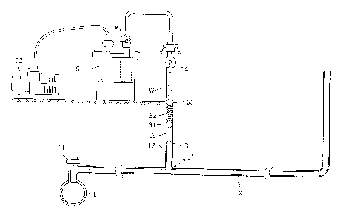
At step 3, as shown in Fig. 4, a lining pig 3' , a second
batch of liquid resin A', a resin transporting pig 31',
a liquid absorbing material 32' , a liquid blocking pig 33' ,
are introduced into the main pipe 12 through the open end 15
with the use of a pressurized liquid W' . Here, the second
batch of resin A' has an amount calculated in view of the length
and diameter of the main pipe 12 and is made sufficient to
cover a length extending from the service tee 11 to the
branching position 12' so as to block the branching position
12' . In this way, after the resin A' has reached the service
tee 11 at the inner end of the main pipe 12, it is sure to
prevent the liquid W' from invading into the branch pipel3.
On the other hand, the pressurized liquid W' has a
predetermined amount which is calculated by subtracting a
total volume (including the lining pig 3', resin A', the
resin transporting pig 31', the liquid absorbing material
32' and the liquid blocking pig 33' ) from the total internal
volume of the main pipe 12.
Referring to Fig. 4, a system for supplying the liquid
W' into the main pipe 12 is just the same as that used
for in j ecting the liquid W into the branch pipe 13 , i . a . ,
9
CA 02255377 1998-12-09
said system includes a liquid tank 4, a liquid pump 41 and
a liquid flow controlling device 42, which are connected in
series by way of hoses 43, 44 and 45.
With the use of a pushing force of the pressurized liquid
W', the lining pig 3', the liquid resin A', the
resin transporting pig 31', the liquid absorbing material
32' , the liquid blocking pig 33' , are all moved forward in
the main pipe 12 until the lining pig 3' arrives at the
service tee 11.
At step 4, as shown in Fig. 5, a pig receiving device
9, a liquid recovering tank 51, a suction pump 52, are
connected in series to the open end 15 of the main pipe 12 ,
thereby forming a suction system for the resin lining
treatment. Then, the suction system is actuated by driving
the suction pump 52 , so as to draw back the liquid W' from
the main pipe 12. With the backward movement of the
liquid W' toward the open end 15 of the main pipe 12, the
resin transporting pig 33', the liquid absorbing material
32', the liquid blocking pig 31', the resin A' and the
lining pig 3' , are all caused to move back towards the open
end 15 of the main pipe 12.
At this moment, since the branching position 12'
is blocked by the lining pig 3 , the main pipe 12 is allowed
to be treated as if it does not involve the branch
pipe 13. Therefore, it becomes possible to prevent the
resin A' from flowing into the branch pipe 13, ensuring
a proper resin lining treatment on the main pipe 12. In
this way, a desired resin lining layer having a uniform
CA 02255377 1998-12-09
thickness may be formed on the internal surface of the main
pipe 12, thereby easily accomplishing the operation of the
resin lining treatment on the main pipe 12.
At step 5 , as shown in Fig . 6 , the pig receiving device
9 , the liquid recovering tank 51, the suction pump 52 , are
connected in series to the open end 14 of the branch pipe 13 ,
thereby forming the same suction system for the resin
lining treatment on the branch pipe 13. Then, the suction
system is actuated by driving the suction pump 52 , so as to
draw back the liquid W from the branch pipe 13. Similarly,
with the backward movement of the liquid W toward the open
end 14 of the branch pipe 13 , the liquid blocking pig 33 ,
the liquid absorbing material 32, the resin transporting
pig 31, the resin A and the lining pig 3 , are all caused
to move back towards the open end 14 of the branch pipe 13.
In this way, a desired resin lining layer having a uniform
thickness may be formed on the internal surface of the branch
pipe 13 , thereby finishing the operation of the resin lining
treatment on the branch pipe 13.
Although it has been described in the above
embodiment that the method of the present invention is
useful for repairing an existing pipeline including a main
pipe and a branch pipe, it is also possible that the
method of the present invention may be used to repair an
existing pipeline including a main pipe and a plurality of
branch pipes , by adding further steps simillar to the above
step 1 ( shown in Fig. 2 ) and step 2 ( shown in Fig. 3 ) after
the completion of the steps 1 and 2 , and by adding further
11
CA 02255377 1998-12-09
steps similar to the above step 5 (shown in Fig. 6) after the
completion of the step 5.
As can be understood from the above description, with
the use of the method according to the present invention,
it has become possible to properly treat and repair an
existing pipeline including a main pipe and one or more
branch pipes, without causing any trouble in the resin
lining treatment, thereby improving the efficiency of
repairing an existing old pipeline and thus reducing a
repairing cost.
While the presently preferred embodiments of the
this invention have been shown and described above, it is
to be understood that these disclosures are for the
purpose of illustration and that various changes and
modifications may be made without departing from the scope
of the invention as set forth in the appended claims.
12