Note: Descriptions are shown in the official language in which they were submitted.
CA 02255461 1998-12-10
A Circuit To Provide Backup Telephone Service For A
Multiple Service Access System Using A Twisted Pair
Field of the Invention
This invention discloses a backup system to provide telephone service for a
subscriber in a wideband communications link layer interface between various
digital
networks and new wideband local loop systems connecting subscribers. More
particularly
it relates to such a system in which such local loops employ metal conductors
as the
medium for such wideband local loops.
Background of the Invention
As deregulation of the telephone industry continues and as companies prepare
to
enter the local telephone access market, there is a need to offer new and
innovative
services that distinguish common carriers from their competitors. This cannot
be
accomplished without introducing new local access network architectures that
will be
able to support these new and innovative services.
Conventionally, customer premises telephone and/or data connections contain
splitters for separating analog voice calls from other data services such as
Ethernet
transported over digital subscriber line (DSL) modems. Voice band data and
voice signals
are sent through a communications switch in a central or local office to an
interexchange
carrier or Internet service provider. DSL data is sent through a digital
subscriber loop
asynchronous mode (DSLAM) switch which may include a muter. The DSLAM switch
connects many lines and routes the digital data to a telephone company's
digital switch.
A major problem with this configuration is that interexchange carriers
attempting
to penetrate the local telephone company's territory must lease trunk lines
from the local
telephone company switch to the interexchange company's network for digital
traffic.
Furthermore, the Internet service provider must lease a modem from the local
phone
CA 02255461 1998-12-10
2
company in the DSLAM switch and route its data through the local phone
company's
digital switch. Thus, the local phone company leases and/or provides a
significant amount
of equipment, driving up the cost of entry for any other company trying to
provide local
telephone services and making it difficult for the interexchange companies to
differentiate
their services. Furthermore, since DSL modem technology is not standardized,
in order to
ensure compatibility, the DSL modem provided by the local telephone company
must
also be provided to the end user in the customer premises equipment (CPE).
Additionally,
since the network is not completely controlled by the interexchange companies,
it is
difficult to for the interexchange companies to provide data at committed
deliver rates.
Any performance improvements implemented by the interexchange companies may
not
be realized by their customers, because the capabilities of the local
telephone company
equipment may or may not meet their performance needs. Thus, it is difficult
for the
interexchange companies to convince potential customers to switch to their
equipment or
to use their services. These factors ensure the continued market presence of
the local
telephone company.
As part of this system, there is a need for improved architectures, services
and
equipment utilized to allow the interexchange companies to offer more products
and
services to customers. DSL technology, one type of communication system that
can use
conventional twisted pair wiring, for which a large infrastructure is in
place, holds the
promise of providing high bandwidth communication into any telephone
subscriber's
home or business. However, such high throughput subscriber links require
properly
functioning systems at both ends of the subscriber link. The possibility of a
power outage
or equipment failure is always present. The prior art does not adequately
address the
problem of providing backup service for such high speed links.
Summary of the Invention
In order to provide an improved network, it is desirable for the interexchange
companies to have access to at least one of the twisted-pair lines connecting
each of the
individual users to the local telephone network before the lines are routed
through the
CA 02255461 1998-12-10
conventional local telephone network equipment. It is preferable to have
access to these
lines prior to the sputter and modem technology offered by the local service
providers.
By having access to the twisted-pair wires entering the customer's premises,
interexchange companies can offer better services by providing higher
bandwidth,
improving the capabilities of the customer premises equipment, and lowering
overall
system costs to the customer by enhancing competition between local exchange
carriers
and interexchange carriers.
The new architecture may utilize a video phone and/or other devices to provide
new services to an end user; an intelligent services director (ISD) disposed
near the
customer's premises for multiplexing and coordinating many digital services
onto a single
twisted-pair line; a facilities management platform (FMP) disposed in the
local telephone
network's central office for routing data to an appropriate interexchange
company
network; and a network server platform (NSP) coupled to the FMP for providing
new and
innovative services to the customer and for distinguishing services provided
by the
interexchange companies from those services provided by the local telephone
network.
As part of this system, one aspect of the invention provides a so-called FMP
which provides a link between the local loop to the customer premises ISD
(which may
also be located remotely from the customer premises) and the interexchange
company
network.
Briefly, in summary, a subscriber link to a central office which employs data
compression, forward error correction, and advanced modulation techniques and
to
connect subscribers to multiple communications networks to provide an array of
services.
A device provides normal telephone service in the event of an equipment
failure. At the
subscriber end, a server called an intelligent services director (ISD)
provides multiple
independent connections for telephones which ordinarily connect to multiple
access
virtual circuits generated on the subscriber link over a twisted pair. A
device called a
facilities management platform (FMP) at the central office end of the link,
among other
things, provides interfacing of the subscriber link to various networks
including a digital
CA 02255461 2001-09-27
4
subscriber loop (DLC) and packet switched networks. Ordinarily telephones
connected to
the ISD require power and correctly functioning modems and controllers in the
ISD and
the FMP to have access to the outside world. A fail-safe mechanism, however
allows at
least one chosen phone to function in the event of a failure. The chosen phone
must be
capable of pulse or DTMF dialing. The connection through which it operate can
be
switched directly to the twisted pair media connecting to the FMP. At the FMP,
the
twisted pair is switched to tie the connection directly to a line card of the
DLC.
In accordance with one aspect of the present invention there is provided a
fail safe
mechanism for a subscriber link over a conductor connecting a subscriber
server with at
least one telephone device to a telephone network facility, comprising: a fail
safe
connection in said subscriber server for said at least one telephone device,
said fail safe
connection being switchable between a normal position connecting said at least
one
telephone device to said subscriber server and a backup position connecting
directly to
said conductor; said telephone network facility having a telephone network
termination
configured to connect an analog telephone; a network interface terminating a
link layer of
said subscriber link at said telephone network facility;
a switch on said network interface such that said conductor is switchable
between said
network interface and said termination, whereby said at least one telephone
device is
connectable to said telephone network termination when said fail safe
connection is in
said backup position; and an analog interface in one of said subscriber server
and said at
least one telephone device connected to permit said at least one telephone to
function as
an analog telephone.
Brief Description of the DraWln$S
The foregoing summary of the invention, as well as the following detailed
description of preferred embodiments, is better understood when read in
conjunction with
the accompanying drawings, which are included by way of example, and not by
way of
limitation with regard to the claimed invention.
Fig. 1 illustrates an embodiment of a hybrid fiber twisted pair local loop
architecture.
Fig. 2 is a block diagram of an embodiment of an intelligent services director
consistent with the architecture shown in Fig. 1.
CA 02255461 2001-09-27
4a
Fig. 3A and 3B illustrate an embodiment of a video phone consistent with the
architecture shown in Fig. 1.
Fig. 4A is a block diagram of an embodiment of a facilities management
platform
consistent with the architecture shown in Fig. 1.
Fig. 4B illustrates a block diagram of an embodiment of a network server
platform consistent with the architecture shown in Fig. 1.
Fig. 5 illustrates life line components of the FMP.
Fig. 6 illustrates life line components of the ISD.
Detailed Description of Preferred Embodiments
The following description provides an overview of how the primary subject of
this
application, a life-line support system, fits into an overall network
architecture. Referring
CA 02255461 1998-12-10
to Fig. l, a first exemplary communication network architecture employing a
hybrid fiber,
twisted-pair (HFTP) local loop 1 architecture is shown. An intelligent
services director
(ISD) 22 may be coupled to a central office 34 via a twisted-pair wire 30, a
connector
block 26, and/or a main distribution frame (MDF) 28. The ISD 22 and the
central or local
office 34 may communicate with each other using, for example, framed, time
division,
frequency-division, synchronous, asynchronous and/or spread spectrum formats,
but in
exemplary embodiments uses DSL modem technology. The central office 34
preferably
includes a facilities management platform (FMP) 32 for processing data
exchanged across
the twisted-pair wire 30. The FMP 32 may be configured to support plain old
telephone
service (POTS) by handling voice signals digitized by the ISD 22 in various
ways. Voice
data can be multiplexed directly onto the digital backplane of a PSTN or
modified digital
loop carrier or it can be formatted for transmission directly on a digital
(for example,
interexchange) network which may be optical or ATM. Ultimately voice data may
be
received by a remote PSTN 46 and transmitted to a called party or through a
remote FMP
32 to the called party. Demodulation of the subscriber link signal (e.g., DSL)
is handled by
a, for example, tethered virtual radio channel (TVRC) modem (shown in Fig.
4A). Non-
voice data may be output to a high speed backbone network (e.g., a fiber-optic
network)
such as an asynchronous transfer mode (ATM) switching network.
The FMP 32 may process data and/or analog/digitized voice between customer
premise equipment (CPE) 10 and any number of networks. For example, the FMP 32
may
be interconnected with a synchronous optical network (SONET) 42 for
interconnection to
any number of additional networks such as an InterSpan backbone 48, the PSTN
46, a
public switch switching network (e.g. call setup SS7-type network 44), and/or
a network
server platform (NSP) 36. Alternatively, the FMP 32 may be directly connected
to any of
these networks. One or more FMPs 32 may be connected directly to the high
speed
backbone network (e.g., direct fiber connection with the SONET network 42) or
they may
be linked via a trunk line (e.g., trunks 40 or 42) to one or more additional
networks. FMP
32 may also interconnect with other FMP 32 units to limit traffic on other
network
facilities for calls destined for nearby FMPs 32. Moreover, calls between two
subscribers
CA 02255461 1998-12-10
'- 6
linked to the same FMP 32 may communicate through the FMP 32 without being
linked to
any of the other network facilities. In addition, the FMP 32 may provide
internal caching to
limit the burden on the external network facilities. For example, a movie
might be cached
during certain time of the day if one particular movie is being requested by
many
subscribers at around the same time.
Although the possibly massive demands of a cache for user data may make it
economically unfeasible to cache data such as movies, the FMP 32 would,
preferably, have
an internal memory or other data storage that would contain information about
each
subscriber to which it is linked. For example, a subscriber may not subscribe
to all the
services the FMP 32 makes available. For example, one subscriber might want
its calls,
where possible, handled by the interexchange carrier by directly routing them
through one
of the digital networks (e.g., ATM) owned by the interexchange carrier or
other owner of
the FMP 32. Another subscriber may prefer to go through the local phone
company
through the modified DLC 87 for at least some calls depending on the pricing
and features
offered by the competing carriers. This data is preferably stored on such an
internal storage
at the FM 32. Such data could be updated by the NSP 46 as required. Storing
such data,
aside from saving bandwidth of external networks, will also speed the handling
of calls.
The NSP 36 may provide a massive cache storage for various information that
may
be provided across the SONET net 42 to the FMP 32 and out to the ISD 22. The
NSP 36
and the FMP 32 may collectively define an access network server complex 38.
The NSP 36
may be interconnected with multiple FMPs 32. Furthermore, each FMP 32 may
interconnect with one or more ISDs 22. The NSP 36 may be located anywhere but
is
preferably located in a point-of presence facility. The NSP 36 may further act
as a gateway
to, for example, any number of additional services. The major tasks of the NSP
46 is to
handle connection management, act as an application launcher and provide
operations
administration maintenance & provisioning.
The ISD 22 may be interconnected to various devices such as a videophone 130,
other digital phones 18, set-top devices, computers, and/or other devices
comprising the
customer premise equipment 10. The customer premise equipment 10 may
individually or
CA 02255461 1998-12-10
collectively serve as a local network computer at the customer site. Applets
may be
downloaded from the NSP 36 into some or all of the individual devices within
the
customer premise equipment 10. Where applets are provided by the NSP 36, the
programming of the applets may be updated such that the applets are be
continually
configured to the latest software version by the interexchange carrier. In
this way, the CPE
may be kept up to date by simply re-loading updated applets. In addition,
certain applets
may be resident on any of the CPE 10. These resident applets may be
periodically
reinitialized by simply sending a request from, for example, a digital phone
18 and/or a
videophone 130 to the FMP 32 and thereafter to the NSP 36 for reinitialization
and
10 downloading of new applets. To ensure wide spread availability of the new
features made
possible by the present architecture, the customer premise equipment may be
provided to
end users either at a subsidized cost or given away for free, with the cost of
the equipment
being amortized over the services sold to the user through the equipment.
Referring to Fig. 2, the ISD 22 may connect with a variety of devices
including
analog and digital voice telephones 15, 18; digital videophones 130, devices
for monitoring
home security, meter reading devices (not shown), utilities devices (not
shown), facsimile
devices 16, personal computers 14, and/or other digital or analog devices.
Some or all of
these devices may be connected with the ISD 22 via any suitable mechanism such
as a
single and/or multiple twisted-pair wires and/or a wireless connection. For
example, a
number of digital devices may be mufti-dropped on a single twisted-pair
connection.
Similarly, analog phones and other analog devices may be mufti-dropped using
conventional techniques.
The ISD 22 may be located within the home/business or mounted exterior to the
home/business. The ISD 22 may operate from electrical power supplied by the
local or
central office 34 and/or from the customer's power supplied by the customer's
power
company. Where the ISD 22 includes a modem, it may be desirable to power the
ISD 22
with supplemental power from the home in order to provide sufficient power to
enable the
optimal operation of the modem.
CA 02255461 1998-12-10
8
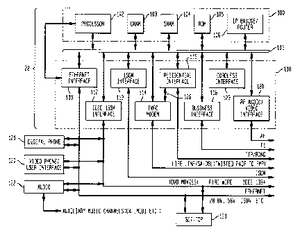
As shown in Fig. 2, in some embodiments the ISD 22 may include a controller
100
which may have any of a variety of elements such as a central processing unit
102, a
DRAM 103, an SRAM 104, a ROM 105 and/or an Internet protocol (IP) bridge
router 106
connecting the controller 100 to a system bus 111. The system bus 111 may be
connected
with a variety of network interface devices 110. The network interface devices
110 may be
variously configured to include an integrated services digital network (ISDN)
interface
113, an Ethernet interface 119 (e.g., for 28.8 kbs data, 56 kbs data, or
ISDN), an IEEE
1394 Afire wire@ interface 112 (e.g., for digital a videodisc device (DVD)), a
TVRC
modem interface 114 (e.g., for a digital subscriber line (DSL) modem), a
residential
interface 114, (e.g., standard POTS phone systems such as tip ring), a
business interface
116 (e.g., a T1 line and/or PABX interface), a radio frequency (RF)
audio/video interface
120 (e.g., a cable television connection), and a cordless phone interface 123
(e.g., a 900
MHZ transceiver). Connected to one of the network interfaces and/or the system
bus 111
may be any number of devices such as an audio interface 122 (e.g., for digital
audio, digital
telephones, digital audio tape (DAT) recorders/players, music for restaurants,
MIDI
interface, DVD, etc.), a digital phone 121, a videophone / user interface 130,
a television
set-top device 131 and/or other devices. Where the network interface is
utilized, it may be
desirable to use, for example, the IEEE 1394 interface 112 and/or the Ethernet
interface
119.
The ISD 22 may be variously configured to provide any number of suitable
services. For example, the ISD 22 may offer high fidelity radio channels by
allowing the
user to select a particular channel and obtaining a digitized radio channel
from a remote
location and outputting the digital audio, for example, on audio interface
122, video phone
130, and/or digital phones 121. A digital telephone may be connected to the
audio interface
122 such that a user may select any one of a number of digital radio cable
channels by
simply having the user push a cable channel button on the telephone and have
the speaker
phone output particular channels. The telephone may be preprogramed to provide
the radio
channels at a particular time, such as a wake up call for bedroom mounted
telephone, or
elsewhere in the house. The user may select any number of services on the
video phone
CA 02255461 1998-12-10
9
and/or other user interface such as a cable set-top device. These services may
include any
number of suitable services such as weather, headlines in the news, stock
quotes,
neighborhood community services information, ticket information, restaurant
information,
service directories (e.g., yellow pages), call conferencing, billing systems,
mailing systems,
coupons, advertisements, maps, classes, Internet, pay-per-view (PPV), and/or
other
services using any suitable user interface such as the audio interface 122,
the video phone /
user interface 130, digital phones, 121 and/or another suitable device such as
a settop 131.
In further embodiments, the ISD 22 may be configured as an IP proxy server
such
that each of the devices connected to the server utilize transmission control
protocol /
Internet protocol (TCP/IP) protocol. This configuration allows any device
associated with
the ISD 22 to access the Internet via an IP connection through the FMP 32.
Where the ISD
22 is configured as an IP proxy server, it may accommodate additional devices
that do not
support the TCP/IP protocol. In this embodiment, the ISD 22 may have a
proprietary or
conventional interface connecting the ISD 22 to any associated device such as
to the set top
box 131, the personal computer 14, the video telephone 130, the digital
telephone 18,
and/or some other end user device.
In still further embodiments, the ISD 22 may be compatible with multicast
broadcast services where multicast information is broadcast by a central
location and/or
other server on one of the networks connected to the FMP 32, e.g., an ATM-
switched
network. The ISD 22 may download the multicast information via the FMP 32 to
any of
the devices connected to the ISD 22. The ISD 22 and/or CPE 10 devices may
selectively
filter the information in accordance with a specific customer user's
preferences. For
example, one user may select all country music broadcasts on a particular day
while
another user may select financial information. The ISD 22 and/or any of the
CPE 10
devices may also be programmed to store information representing users'
preferences
and/or the received uni-cast or multicast information in memory or other
storage media for
later replay. Thus, for example, video clips or movies may be multicast to all
customers in
the community with certain users being preconfigured to select the desired
video clip/
movie in real time for immediate viewing and/or into storage for later
viewing.
CA 02255461 1998-12-10
Referring to Fig. 3A, a videophone 130 may include a touch screen display 141
and
soft keys 142 around the perimeter of the display 141. The display may be
responsive to
touch, pressure, and/or light input. Some or all of the soft keys 142 may be
programmable
and may vary in function depending upon, for example, the applet being run by
the
5 videophone 130. The function of each soft key may be displayed next to the
key on the
display 141. The functions of the soft keys 142 may also be manually changed
by the user
by pressing scroll buttons 143. The videophone 140 may also include a handset
144 (which
may be connected via a cord or wireless connection to the rest of the
videophone and/or
directly to the ISD), a keypad 150, a video camera 145, a credit card reader
146, a smart
10 card slot 147, a microphone 149, a motion and/or light detector 148, built-
in speakers)
155, a printer/scanner/facsimile 152, and/or external speakers 154 (e.g.,
stereo speakers). A
keyboard 153 and/or a postage scale 151 may also be connected to the
videophone 130.
Any or all of the above-mentioned items may be integrated with the videophone
unit itself
or may be physically separate from the videophone unit. A block diagram of the
video
phone unit is shown in Fig. 3B. Referring to Fig. 3B, in addition to the items
above, the
video phone 130 may also include a signal processor 171, high speed interface
circuitry
172, memory 173, power supply 174, all interconnected via a controller 170.
When the videophone 130 is used as a video telephone, the display 141 may
include one or more video windows) 160 for viewing a person to whom a user is
speaking
and/or showing the picture seen by the person on the other end of the video
phone. The
display may also include a dialed-telephone-number window 161 for displaying
the phone
number dialed, a virtual keypad 162, virtual buttons 163 for performing
various telephone
functions, service directory icons 165, a mail icon 164, and/or various other
service icons
166 which may be used, for example, for obtaining coupons or connecting with
an
operator. Any or all of these items may be displayed as virtual buttons and/or
graphic icons
and may be arranged in any combination. Additionally, any number of other
display
features may be shown on the video phone in accordance with one or more of the
applications incorporated by reference below.
CA 02255461 1998-12-10
11
Referring to Fig. 4A, the FMP 32 may coordinate the flow of data packets,
separate
voice signals from other signals, perform line monitoring and switching
functions, and/or
convert between analog and digital signals. The FMP 32 may process data sent
from the
CPE 10 to the central or local office 34 by separating and reconstructing
analog voice
signals, data, and control frames. The FMP 32 may process data sent from the
central or
local office 34 to the CPE 10 by separating control messages from user
information, and
configure this information into segments for transport across the digital
subscriber loop.
The FMP 32 may also terminate all link layers associated with the digital
subscriber loop.
In some embodiments, the FMP 32 may include an access module 70 and a digital
loop carrier 87. The access module 70 may include a line protector 71, a cross-
connector
73, a plurality of TVRC modems 80, a plurality of digital filters 82, a
controller
multiplexes 84, and/or a muter and facilities interface 86. The digital loop
carrier 87 may
include a plurality of line cards 96, a time domain multiplexing (TDM)
multiplexes (MUX)
88, a TDM bus 90, a controller 92, and/or a facilities interface 94.
During normal operations, digital signals on the subscriber lines 30 (e.g.,
twisted-
pair lines) containing both voice and data may be received by the TVRC modems
80 via
the line protector 71 and the cross-connector 73. Preferably, the line
protector 71 includes
lightning blocks for grounding power surges due to lightning or other stray
voltage surges.
The TVRC modems 80 may send the digital voice and/or data signals to the
controller
multiplexes 84 and the digital filters 82. The digital filters 82 may separate
the voice
signals from the digital data signals, and the controller multiplexes 84 may
then multiplex
the voice signals and/or data signals received from the digital filters 82.
The controller
multiplexes 84 may then send multiplexed voice signals to the TDM MUX 88 and
the data
signals to the routes and facilities interface 86 for transmission to one or
more external
networks. The TDM MUX 88 may multiplex the voice signals from the controller
multiplexes 84 and/or send the voice signals to the TDM bus 90, which may then
send the
digital voice signals to the controller 92 and then to the facilities
interface 94 for
transmission to one or more external networks. Alternatively, voice data may
be
repackaged by controller & multiplexes 84 for application directly to any of
various digital
CA 02255461 1998-12-10
12
networks without going through modified DLC 87. Both the muter and facilities
interface
86 and the facilities interface 94 may convert between electrical signals and
optical signals
when a fiber optic link is utilized.
When there is a failure of the digital data link (e.g., if there is a failure
of the TVRC
modems 80 at the FMP 32 or the TVRC modem 114 at the ISD 22), only analog
voice
signals might be sent over the subscriber lines 30. In such a case, the analog
voice signals
may be directly routed to the line cards 96, bypassing the TVRC modems 80, the
digital
filters 82, the controller multiplexer 84, and the TDM MUX 88. Thus, voice
communication is ensured despite a failure of the digital data link. The line
cards 96 may
convert the analog voice signals into digital format (e.g., TDM format) and
send the
digitized voice data onto the TDM bus 90 and eventually through the controller
92 and the
facilities interface 94 for transmission to one or more external networks.
Refernng to Fig. 4B, the NSP 36 may be variously configured to provide any
number of services provided by a server such as information services, Internet
services,
pay-per-view movie services, data-base services, commercial services, and/or
other
suitable services. In the embodiment shown in Fig. 4B, the NSP 36 includes a
muter 185
having a backbone 180 (e.g., a fiber distributed data interface (FDDI)
backbone) that
interconnects a management server 182, an information/database server 183,
and/or one or
more application server clusters 184. The NSP 36 may be connected via the
muter 185 by a
link 181 to one or more external networks, NSPs 36, and/or an FMPs 32. The
information/data base server 183 may perform storage and/or database
functions. The
application server cluster 184 may maintain and control the downloading of
applets to the
ISD 22. The NSP 36 may also include a voice/call processor 186 configured to
handle call
and data routing functions, set-up functions, distributed operating system
functions, voice
recognition functions for spoken commands input from any of the ISD connected
devices
as well as other functions.
Referring again to Figs. 1 and 4A, as mentioned, the FMP 32 serves a link-
layer
termination for the high-speed subscriber data link, for example, a DSL link
between the
ISD 22 at a customer premise and the digital network of an interexchange
carrier (shown in
CA 02255461 1998-12-10
13
Fig. 1). The FMP 32 communicates with the ISD 22, receiving signaling data,
user data,
and voice data over (preferably) a high speed DSL link. The signaling data
tells the FMP
32 how to handle (route) the voice and user data. There are two major routing
alternatives,
to route as a normal call through the modified DLC 87 or to route directly
through the
interexchange carrier network by converting the user and voice data directly
from the
format of the subscriber link to the format of the interexchange carrier
network used. In
the latter case, a dialogue between the FMP 32 and the NSP 46 may be
established to
inform the NSP 46 that a call is impending or terminated and to request that
it allocate or
deallocate bandwidth of the network accordingly. The following is a detailed
description of
the elements of a preferred embodiment of the FMP 32.
FMP 32 receives digital data over a twisted pair connection (preferred, but
could be
any other medium) which terminates at a line protection block 71. In an
embodiment, the
FMP 32 supports DSL communication with the ISD 22. The termination to which
twisted
pair wiring connects the ISD 22 with the FMP 32 is responsible for terminating
the DSL
link. This includes providing Borscht as well as DSL modem functions.
During normal operation the DSL Facilities Termination subsystem is
responsible
for providing over-voltage protection. This is the same as in a convention
wire termination.
In addition, the FMP 32 includes DSL modems or TVRC modems 80 to convert
analog
symbols to digital data and vice versa using for example M-PSK or M-QAM
modulation/demodulation. These techniques are described in the literature and
applications
incorporated by reference in the present application.
Another function of the FMP 32 is to provide in-service testing/monitoring of
the
ISD facility. This aspect stems from the fact that the FMP 32 stands in the
shoes of the
DLC it supplements.
On the network side of the modems, data must be framed before being modulated
to be transmit over the DSL link. Other preparations include encoding for
forward error
correction (for data not suited to retransmission such as voice data) and
interleaving (to
reduce drastic effects of impulsive noise or fading).
CA 02255461 1998-12-10
14
The final output of the termination/modem subsystem is a stream of DSL frames
containing higher-layer protocol data. In the CPR-to-network direction. The
controller &
multiplexer 84 processes the DSL frames it receives from the Facilities
Termination
subsystem to terminate any link layers associated with the DSL segment of the
connection,
(in an embodiment) re-construct (e.g. IPv6) packets from the DSL frames, and
separate
(IP) packets containing voice, data, and signaling (call-routing or data
routing)
information.
In an embodiment of the invention, for purposes of transmitting voice data
directly
from an external digital network (as opposed to through modified DLC 87) data
containing
voice (for example, in voice-packets) are delivered by the controller &
multiplexer 84 to a
packet-to-circuit translation subsystem (not shown separately) by an internal
network
system (also not shown separately). User data packets are delivered to/from
the external
networks (which can be interexchange carrier networks or any other external
network) and
signaling packets to/from the subscriber signaling subsystem of the external
network where
user data or voice data are routed directly as packets or to/from controller
92 where user or
voice data are routed through modified DLC 87.
In the network-to-CPE direction, the controller & multiplexer 84 processes the
packets it receives from all subscriber signaling and external routing
subsystems. This
involves multiplexing (at the packet level) voice, data and subscriber
signaling packets
bound for a single DSL link. It also involves mapping packets onto DSL frames,
and
terminating the FMP-side of any link layers associated with the DSL link.
Packets
traveling in the network-to-CPE direction are sent directly to the DSL
termination for
delivery to ISD 22.
For purposes of transferring data between its subsystems, such as within the
controller & multiplexer 84, voice, data, and signaling packets are
transported via an
internal routing system (not shown separately) that is at least logically, and
perhaps
physically also, distinct from the external networks with which the FMP 32
communicates.
This is useful for reliability, security, and availability reasons.
CA 02255461 1998-12-10
In Fig. 4A, various elements of the FMP 32, which could be on a single plug-in
card that accommodates terminations for four subscribers lines, are shown.
Each of the
four subscribers can be connected to a respective (any) one of five TVRC
modems 80
(TVRC or DSL preferred, but could be any type of digital modem) via a cross-
connector
5 switch. In the event of a failure of one of modems the ISD 22 indicated by,
for example,
irregular communications detected in controller & multiplexer 84 or controller
92, cross
connector 73 will switch the subscriber from the suspected bad TVRC modem to a
spare
one of the five TVRC modems 80. The FMP 32 could employ failure indicators
(not
shown) to advise maintenance personnel that a modem has been switched out and
that it
10 should be replaced. TVRC modems 80 are high speed digital modems with the
ability to
transmit and receive data at rates of 1 Mbit or more using advanced
modulation, error-
correction coding, and data compression techniques. These are preferred known
technologies and are described in other references including some of the
copending
applications incorporated by reference in the present application. No
particular technology
15 or technique is identified with modems 80 and more advanced technologies
may be
employed with the present invention.
Referring now also to Figs. 5 and 6, a lifeline may be provided for continuous
telephone service in the event of a power failure at the CPE 10. The lifeline
may be utilized
to connect the ISD 22 to the local telecommunications company's modified DLC
87, for
example in the FMP 32 located in the central office 34. The five modem
connections to the
cross connector 73 are switchable to respective connections to five line cards
to provide
telephone service (life line service) in the event that the ISD 22 becomes
inoperative. In a
conventional digital loop carrier (as opposed to modified DLC 87) the line
cards connect
over twisted pairs to POTS to interface the digital backplane 90 and the
analog POTS. In
the modified DLC 87, they serve the same purpose when the line card is
switched-in and
the TVRC modem switched-out due to failure of a connected ISD 22. That is, the
line
cards serve as the terminations of the analog phone lines providing power to
the telephones
via a battery, supplying the ringing voltage power, out of service testing and
supervision of
the subscriber terminal as well as interfacing the digital communications on
the TDM
CA 02255461 1998-12-10
16
backplane 90 to the analog system of the calling/called POT. Thus, in the
event of failure
of an ISD 22, the FMP, for that particular line, acts like a conventional DLC
because the
entire access module 70 and its features and the modified aspects of the DLC
87 are
bypassed. In the event of a failure at the customer premises, battery supply
to the
subscriber line, out-of service testing, ringing voltage supply, and
supervision of
subscriber terminals are also provided.
Referring now more particularly to Fig. 5, a termination facility for
subscriber lines
30 of access module 70 provides, in addition to line protection 71 and cross
connector 73, a
line monitor and controller 82. The latter may be a separate component or it
may be a
programmed function of controller & multiplexer 84. Line monitor controller 82
controls
the life line switches 78 which, although shown schematically as SPDT
switches, are
preferably DPDT switches. When a subscriber link is lost due to malfunction, a
corresponding one of life line switches 78 is tripped from a position in which
it connects
the subscriber line to the modem 80 to a position in which it connects a
respective line card
96. A corresponding life line switch 144 in the ISD 22 disconnects an analog
telephone
121 from the tip ring interface 142 and connects the analog phone 121 directly
to the
subscriber lines 30. In these positions, the analog phone 121 is connected to
the line card
96 as in ordinary telephone service so that the DLC 87 supplies battery backed
up power,
ringing, DTMF decoding, etc. This configuration provides normal telephone
service
through the analog telephone 121.
Referring particularly to Fig. 6, in the ISD 22 the life line switch 144 is
controlled
by a line monitor controller 141. The latter may be a separate part of the ISD
22 (preferably
powered by battery in the even of a power outage) or it may be a function of
an ISD
controller 145 that controls the various functions of the ISD described
elsewhere in the
present application and in the copending applications incorporated by
reference. The line
monitoring facilities 141 and 82 controlling the life line switches 78 and 144
may monitor
the integrity of the subscriber link by various means. In one preferred
implementation,
these line monitors are battery powered components that listen for a message
generated
from the opposite end of the subscriber link 30 and, if they don't receive it
within a period
CA 02255461 1998-12-10
17
of time, they go to the default life-line-connected states. The switches would
also have a
power-off state connecting the life line circuit.
Referring now to Fig. 7, another embodiment of the life line service is shown.
In
this embodiment, the analog telephone is connected permanently to the line
card of the
DLC 87 of the FMP 32. In this case, since the frequencies normally used by the
plain old
telephone service (POTS) range up to only about 4 kHz, the range used by the
modems can
simply avoid this portion without being substantially limited. So, for
example, the modem
124 and 80 may use only the frequency range above 100kHz . This range would
leave the
range used by ISDN service available too. Power can still be supplied through
the
subscriber link 30. Thus, in the embodiment of life line service shown in Fig.
7, one or
more regular telephones are connected to the subscriber twisted pair line
(shown
schematically as a single line, although in practice it is usually two twisted
conductors).
The subscriber twisted pair is connected to the line card 96 as in normal
telephone service
and the available frequencies above the range used by the POTS are used for
the multiple
access subscriber link discussed in this specification and in the related
applications.
Under normal operation, the TVRC modems 80 demodulate a symbol (e.g., QAM,
PSK, etc.) generated on the subscriber lines 30 to output subscriber data
including voice,
signaling, and user data, and apply the resulting data stream to the digital
filters 82. As
discussed above, the digital data from the ISDs 22 contain voice, digital
information, and
signaling from, potentially, many different subscriber equipment all
multiplexed into the
same data stream, preferably a packet-based protocol as discussed above. At a
time when a
call is just being dialed by the user, the data stream will contain signaling
information
(unless a voice-activated dialing feature is being used as discussed further
below). At other
times, signaling data may be generated automatically by subscriber equipment
such as a
settop unit in the process of ordering a movie.
Call setup may be performed in a way that bypasses the normal interaction
between
the regular DLC (not shown) and the modified DLC 87 because the ISD 22 may
send call
signaling data as digital information to the FMP 32. Thus, there may be no
need to
interpret DTMF tones or dialing pulse. The FMP 32 may interact through the
controller 92
CA 02255461 1998-12-10
18
set up the call conventionally through the modified DLC 87 by way of the TDM
multiplexer 88. Or the signaling data from the subscriber link may be
transmitted in the
form of DTMF tones which are interpreted either through a DLC facility or by a
detector in
FMP 32. The direct mechanism for handling signaling data is preferred because
DTMF
tones would take up bandwidth unnecessarily.
Alternatively, calls can be routed directly to the digital network as packet
data, for
example. In such a process, where calls are placed digitally through the
packet network,
signaling information may be sent to the NSP 46 along with control information
informing
the NSP 46 that a virtual circuit for a call is requested. If it is a voice
call, a high priority
must be given to the virtual circuit and the NSP 46 must make sure the
bandwidth is
available. At the time a call is made which is to be routed directly from the
FMP 32
through the packet-switched networks (e.g., SONET or ATM), the FMP 32 may be
handling data to and from the subscribers. At the time the request for a high
priority voice
channel is made, the ISD 22 has already de-allocated bandwidth assigned for
data
transmission to make room for the higher priority voice transmission. The FMP
32
communicates the demand for high priority bandwidth to the NSP 46 and the NSP
36 may
deallocate bandwidth formerly dedicated to data transmission (the same data
for which
bandwidth was de-allocated by the ISD 22) as it, at the same time, allocates
bandwidth for
the high priority call. This may involve a transmission from the FMP 32 to the
NSP 46
telling the NSP 46 that less low-priority data bandwidth is needed in the
current call and
high priority bandwidth is needed for the new voice call. The NSP 46 then
responds by
allocating or identifying available circuits (virtual) and providing the
appropriate signaling.
When the voice call is finished, similar dialogue between the FMP 32 and NSP
46 takes
place. The termination of the call is detected by the FMP 32 and a message
sent to the NSP
46 informing it that additional bandwidth is needed for data communications
and no (or
less) bandwidth for the voice call.
In the preferred embodiment, the voice and digital information is time domain
multiplexed (TDM) in the digital data stream applied to the digital filters
82. This
embodiment makes it simple and efficient to provide high priority to voice
CA 02255461 1998-12-10
19
communications by the ISD 22 by providing a bandwidth on demand as discussed
elsewhere in this application and in related applications incorporated by
reference in this
application. In the TDM system of the preferred embodiment, it is also
convenient to filter
out digitally voice data from the demodulated data streams and apply this data
directly to
the TDM backplane 90. The latter requires some discussion regarding routing.
The TDM multiplexes 88 takes the place of multiple line cards. As mentioned,
it is
the job of the line cards 96 in a conventional DLC to convert voice data to
digital data and
apply it to the TDM backplane 90. In so doing, it will also be the job of the
control 92 and
the facilities interface 94 to handle circuit (TDM) to/from packet conversion.
In
conventional DLCs voice data also includes DTMF tones which are decoded in the
line
cards 96 and used by the controller 92 for call setup. The same job is
performed by the
TDM multiplexes 88. Instead of DTMF tones, the routing data (called number,
call
origination data, signaling, etc.) are applied in digital form directly to the
TDM backplane
90 for handling by the controller 92. Thus, TDM multiplexes 88 creates the
appearance of
being a line card (or set of line cards) to the controller and other
facilities from the TDM
backplane 90 and out through the interexchange network. The TDM multiplexes
can be
plugged as a single card directly into the TDM backplane 90. To the core
network (the
conventional switched network such as connected through the DLC), all
equipment
including the NSP 46, the FMP 32 appears to be a conventional DLC. This is
advantageous, since there is minimal impact to the remainder of the network
when the
equipment is integrated into the network. This configuration provides a
seamless interface
between the fully digital telephone linked through the ISD 22 and the modified
DLC 87. It
also provides a system that allows packet switched voice and data to work side
by side and
together with traditional digital loop carrier equipment.
In the preferred embodiment, in the CO to CPE direction, the FMP 32 performs
the
following functions. First, the FMP 32 breaks up the control messages and
packets
containing user data into segments that fit into the DSL frames. Secondly, the
FMP 32
multiplexes these frames together with frames containing speech so that the
can be
transported to the ISD 22 over the DSL link. Third, the FMP 32 terminates all
link layers
CA 02255461 1998-12-10
associated with the DSL segment of the connection. The reverse happens in the
CPE to CO
direction. Fig. 5 shows how the access module takes information from the DSL
modems
201 and places the voice V1, V2, etc. and data D1, D2, etc. into frames 203,
then
multiplexes the frames 203. Consider a scenario where data is fed to the TVRC
modems
5 201 and a voice call comes in. Assume that 1 Mbps is available for
information transfer via
the TVRC modems 201. Prior to the incoming call, all 1 Mbps is used up.
However, as
soon as a voice call comes in, since voice has a higher priority that data, a
64 Kbps channel
(slot) is deallocated from data usage and is allocated for voice. If a second
voice call comes
in, then another data channel will be deallocated from data usage and
allocated for voice.
10 As the voice call gets terminated, then the allocated voice slots will be
reallocated to use by
data. Hence, the system dynamically allocates bandwidth in real time to
maximize
information transfer. Note that this time domain multiplexing could be
performed with
frequency domain multiplexing, as with a multitone channel, as well.
Within the local access side of the local loop, multiple FMPs 32 may be
grouped
15 and served by a single NSP 46. Each FMP 32 is in turn interconnected to a
plurality of
ISDs which serves the subscribers in a given local loop. Usually, the NSP 46
will be
located in an AT&T Point-of Presence (POP). However, this might not be
possible in all
areas and it could possibly be co-located with other equipment, depending on
space
availability.
20 Although, as discussed above, the TDM multiplexer 90 allows a seamless
interface
between the "old technology" DLC and "new technology" employing the access
module 70
and the modified DLC 87 and other elements of the architecture described here
and in
related applications, substantial modifications to software of the controller
92 will provide
additional features. These features are discussed here, elsewhere in this
application, and in
the related application incorporated by reference in this application. For
example, when
multiple calls to the same called party are made, the modified DLC 87 must
handle such
calls differently. In a conventional setup, a message would be sent by the DLC
87 that the
called party is off hook. In the current system of the invention, the called
party may still
receive additional calls to the same party. Another example of how software
modifications
CA 02255461 1998-12-10
21
for handling of voice calls is provided by the voice-activated call example
that follows,
after a discussion of the interaction between the NSP 36 and the FMP 32. Note
that the
details of such software modifications are not necessary to discuss in detail
as such are
quite straightforward to implement.
To illustrate the interaction between the various components of the instant
invention, a voice dialing scenario will be described. When a subscriber picks
up the
telephone and if no digits have been dialed after a specified period of time
has elapsed, the
ISD 22 may start digitizing the voice information into data, for example, 64
Kbps -law
PCM data. The voce samples are then stored in a wave file, which is
subsequently
I O transmitted to the FMP 32. On receipt by the FMP 32, the FMP 32 will
forward the
information to the NSP 36. The NSP 36 will attempt to authenticate the request
by
ensuring that the subscriber does indeed have a subscription to the voice
dialing service.
The NSP 36 can determine the identity of the subscriber by looking at the
address in a
certain field of the packet. The NSP 36 can therefore interpret the
information in the wave
15 files and take the appropriate action. Let us assume that subscriber John
wanted to call
another subscriber Paul. The NSP 36 will also attempt to determine who is Paul
as defined
by John. Once the telephone number for John has been determined, the NSP 36
will inform
the FMP 32 to set up a call to John's number. The FMP 32 will then go through
the
facilities interface 94 to set up the call. In an embodiment, this would be
over TR303
20 interface and the signal would be sent to a DLC to request the local
Serving Office to
indicate the appropriate ports to use for setting up the call. The FMP 32 has
its own DTMF
and tone generator which is used for signaling when the interexchange carrier
network is to
be bypassed in routing a call. For example, the FMP 32 may be connected to a
switched
network that requires the generation of DTMF signals to set up a call. Such a
call can be
25 handled through the FMP 32.
Note that there is a significant advantage implicit in the preferred design.
The voice
dialing service may be provided by a different company from the one that
actually connects
the call. There is no need to pay for the Local Exchange Carrier (LEC) for
providing such a
CA 02255461 1998-12-10
22
service and it can all be done with a single facility. Similar services, such
as speed dialing,
that the LEC provides can now be made available locally.
In the case where there is an incoming call, say from the PSTN, the FMP will
get
the information from the DLC. The information will be dispatched over the
signaling
channel to the NSP 36. The NSP 36 will instruct the FMP 32 with the
information on how
the call should be terminated. On receiving this message, the FMP 32 will send
the
appropriate signaling message to the ISD 22. The ISD 22 "knows" which phones
are in use
and which ones are not. As a result, it will apply ring to a phone that is
free.
In the CPE to CO direction, data "left over" after filtering of voice data is
accomplished by the digital filters 84 is transmitted by the access module to
the
interexchange network. This data includes routing data as well as content. The
link layer
interface is provided by the controller and multiplexes 84 of the access
module 70. Thus,
for example, if the exported data is to be transmitted over an external ISDN
interface, the
data from digital filters 82 would be formatted and timed to be applied to
such an interface
by the controller and multiplexes 84 of the access module 70.
In the disclosure of the instant invention, Tethered Virtual Radio Channel
(TVRC)
is the preferred modulation technique. However, the instant invention is not
limited to the
use of TVRC modulation technology. However, TVRC would prove to be a major
advantage over other proposed schemes, since it provides an alternate to
interleaving which
is used to overcome impairments such as noise and interference and which
results in
unacceptable delays.
In addition to monitoring the link between the ISD 22 and the FMP 32 for
purposes
of identifying a failure of the ISD 22 (which requires life-line support), the
FMP 32 may
provide other line monitoring functions, such as off hook detection, through
interaction
with the intelligent ISD 22. For example, a subscriber, although the bandwidth
is available
to send an additional call to the same called number, may not wish to have
additional calls
ring through. The FMP 32 in such a case could respond to an additional call
with a busy
signal or voice mail.
CA 02255461 1998-12-10
23
In some embodiments, the FMP 32 may be configured to appear to the network as
a
conventional DLC. As an alternative configuration, the FMP 32 may be
configured directly
to connect to the ATM without transport across the SONET network. It may be
desirable to
transmit the voice data from the FMP 32 to the PSTN 42 over a high speed
packet network
(e.g. ATM), which is superimposed on top of the SONET network. This has an
advantage
in that the packet transmission of voice information can be more efficient
than more
conventional treatment (for example, it is susceptible to a high degree of
compression).
However, it requires additional management to manage delays, buffer overruns,
drop
packets, etc., across the ATM network as mentioned above.
The following applications, filed concurrently herewith, are hereby
incorporated
by reference:
1. A Hybrid Fiber Twisted-pair Local Loop Network Service Architecture
(Gerszberg
41-3-13);
2. Dynamic Bandwidth Allocation for use in the Hybrid Fiber Twisted-pair Local
Loop Network Service Architecture (Gerszberg 42-4-14);
3. The Videophone (Gerszberg 43-9-2);
4. Videophone Privacy Activator (Gerszberg 44-10-3);
5. Videophone Form Factor (Gerszberg 45-11-4);
6. Videophone Centrally Controlled User Interface With User Selectable Options
(Gerszberg 46-12-5);
7. Videophone User Interface Having Multiple Menu Hierarchies (Gerszberg 47-13-
6);
8. Videophone Blocker (Gerszberg 79-38-26);
9. Videophone Inter-com For Extension Phones (Gerszberg 48-14-7);
10. Advertising Screen Saver (53-17);
11. Videophone FlexiView Advertising (Gerszberg 49-15-8);
12. Videophone Multimedia Announcement Answering Machine (Gerszberg 73-
32-20);
CA 02255461 1998-12-10
24
13. Videophone Multimedia Announcement Message Toolkit (Gerszberg 74-33-
21 );
14. Videophone Multimedia Video Message Reception (Gerszberg 75-34-22);
15. Videophone Multimedia Interactive Corporate Menu Answering Machine
Announcement (Gerszberg 76-35-23);
16. Videophone Multimedia Interactive On-Hold Information Menus (Gerszberg
77-36- 24);
17. Videophone Advertisement When Calling Video Non-enabled Videophone
Users (Gerszberg 78-37-25);
18. Motion Detection Advertising (Gerszberg 54-18-10);
19. Interactive Commercials (Gerszberg 55-19);
20. Videophone Electronic Catalogue Service (Gerszberg 50-16-9);
21. A Facilities Management Platform For Hybrid Fiber Twisted-pair Local Loop
Network, Service Architecture (Barzegar 18-56-17);
22. Multiple Service Access on Single Twisted-pair (Barzegar (16-51-15);
23. Life Line Support for Multiple Service Access on Single Twisted-pair
(Barzegar 17-52-16);
24. A Network Server Platform (NSP) For a Hybrid Fiber Twisted-pair (HFTP)
Local Loop Network Service Architecture (Gerszberg 57-4-2-2-4);
25. A Communication Server Apparatus For Interactive Commercial Service
(Gerszberg 58-20-11);
26. NSP Multicast, PPV Server (Gerszberg 59-21-12);
27. NSP Internet, JAVA Server and Videophone Application Server (Gerszberg 60-
5-3-22-18);
28. NSP WAN Interconnectivity Services for Corporate Telecommuters (Gerszberg
71-9-7-4-21-6);
29. NSP Telephone Directory White-Yellow Page Services (Gerszberg 61-6-4-23-
19);
CA 02255461 1998-12-10
30. NSP Integrated Billing System For NSP services and Telephone services
(Gerszberg 62-7-5-24-20);
31. Network Server Platform / Facility Management Platform Caching Server
(Gerszberg 63-8-6-3-5);
5 32. An Integrated Services Director (ISD) For HFTP Local Loop Network
Service
Architecture (Gerszberg 72-36-22-12);
33. ISD and Videophone Customer Premise Network (Gerszberg 64-25-34-13-5);
34. ISD Wireless Network (Gerszberg 65-26-35-14-6);
35. ISD Controlled Set-Top Box (Gerszberg 66-27-15-7);
10 36. Integrated Remote Control and Phone (Gerszberg 67-28-16-8);
37. Integrated Remote Control and Phone User Interface (Gerszberg 68-29-17-9);
38. Integrated Remote Control and Phone Form Factor (Gerszberg 69-30-18-10) ;
39. Videophone Mail Machine (Attorney Docket No. 3493.73170);
40. Restaurant Ordering Via Videophone (Attorney Docket No. 3493.73171);
15 41. Ticket Ordering Via Videophone (Attorney Docket No. 3493.73712);
42. Mufti-Channel Parallel/Serial Concatenated Convolutional Codes And Trellis
Coded Modulation Encode/Decoder (Gelblum 4-3);
43. Spread Spectrum Bit Allocation Algorithm (Shively 19-2);
44. Digital Channelizer With Arbitrary Output Frequency (Helms 5-3);
20 45. Method And Apparatus For Allocating Data Via Discrete Multiple Tones
(filed
12/22/97, Attorney Docket No. 3493.20096--Sankaranarayanan 1-1);
46. Method And Apparatus For Reducing Near-End Cross Talk In Discrete Mufti-
Tone
Modulators/Demodulators (filed 12/22/97, Attorney Docket No. 3493.37219--
Helms 4-32-18).
While exemplary systems and methods embodying the present invention are
shown by way of example, it will be understood, of course, that the invention
is not
limited to these embodiments. Modifications may be made by those skilled in
the
art, particularly in light of the foregoing teachings. For example, each of
the
CA 02255461 1998-12-10
26
elements of the aforementioned embodiments may be utilized alone or in
combination with elements of the other embodiments.