Language selection

Search

Patent 2255492 Summary

Third-party information liability

Some of the information on this Web page has been provided by external sources. The Government of Canada is not responsible for the accuracy, reliability or currency of the information supplied by external sources. Users wishing to rely upon this information should consult directly with the source of the information. Content provided by external sources is not subject to official languages, privacy and accessibility requirements.

Claims and Abstract availability

Any discrepancies in the text and image of the Claims and Abstract are due to differing posting times. Text of the Claims and Abstract are posted:

  • At the time the application is open to public inspection;
  • At the time of issue of the patent (grant).
(12) Patent Application: (11) CA 2255492
(54) English Title: SPRING CORE FOR MATTRESS OR CUSHION
(54) French Title: LAME A RESSORT POUR MATELAS OU COUSSINS
Status: Deemed Abandoned and Beyond the Period of Reinstatement - Pending Response to Notice of Disregarded Communication
Bibliographic Data
(51) International Patent Classification (IPC):
  • A47C 23/02 (2006.01)
  • A47C 27/06 (2006.01)
  • A47C 27/14 (2006.01)
  • A47C 27/20 (2006.01)
  • F16F 1/18 (2006.01)
  • F16F 3/02 (2006.01)
  • F16F 3/10 (2006.01)
(72) Inventors :
  • KUTSCHI, FRANZ (Austria)
(73) Owners :
  • FRANZ KUTSCHI
(71) Applicants :
  • FRANZ KUTSCHI (Austria)
(74) Agent: SMART & BIGGAR LP
(74) Associate agent:
(45) Issued:
(22) Filed Date: 1998-12-08
(41) Open to Public Inspection: 1999-06-09
Availability of licence: N/A
Dedicated to the Public: N/A
(25) Language of filing: English

Patent Cooperation Treaty (PCT): No

(30) Application Priority Data:
Application No. Country/Territory Date
A2082/97-1 (Austria) 1997-12-09

Abstracts

English Abstract


The invention relates to a spring core for mattresses and seat cushions with
leaf springs. The spring core consists of a plurality of spring elements bent up out
of passages punched in a plate, with each spring element having an upper and a
lower spring clip, with the upper spring clip bent up out of a passage punched in
the lower spring clip. The spring elements can also be coated with extruded foam.


Claims

Note: Claims are shown in the official language in which they were submitted.

I claim:
1. A leaf spring core for mattresses and seat cushions comprising:
a plurality of spring elements bent up out of passages punched in a plate,
including a plurality of lower spring clips bent up out of passages punched in said
plate and a plurality of upper spring clips bent up out of passages punched in said
lower spring clips.
2. The leaf spring core of claim 1, further comprising:
a coating of extruded foam;
wherein said plurality of spring elements contain interior portions which are
free of said extruded foam.
3. The leaf spring core of claim 2, wherein:
said spring elements are individual spring elements;
said individual spring elements are arranged one after the other in
succession; and
said individual spring elements are coated with said foam.
4. The leaf spring core of claim 2, wherein:
said plurality of lower spring clips and said plate define a plurality of lower
exterior spaces; and
said lower exterior spaces are free of said foam.
5. A method of forming a leaf spring core, comprising the steps of:
producing a plate with at least one set of passages, each set defining first
-5-

and second portions of said plate;
forming a lower spring clip by bending said first portion; and
forming an upper spring clip by bending said second portion attached to
said first portion;
wherein said lower spring clip and said upper spring clip form a spring
element.
6. The method of claim 5, further comprising the step of:
defining an interior space formed between said lower spring clip and said
upper spring clip;
coating said spring element with foam; and
leaving said interior space essentially free of foam.
7. The method of claim 5, further comprising the step of:
defining an interior space formed between said lower spring clip and said
upper spring clip;
defining an exterior space formed between said lower spring clip and said
plate;
coating said spring element with foam;
leaving said interior space essentially free of foam; and
leaving said exterior space essentially free of foam.
8. The method of claim 5, wherein the step of producing a plate includes
punching said passages from said plate.
-6-

Description

Note: Descriptions are shown in the official language in which they were submitted.


CA 022~492 1998-12-08
SPRING CORE FOR MATTRESS OR CUSHION
BACKGROUND OF THE INVENTION
1. Field of the Invention
The invention relates to a spring core formattresses and seat cushions with
5 leaf springs.
2. Description of the Related Technolog;y
Spring cores formattresses and seat cushions with spiral springs are known.
These spring cores, which come in various embodiments, are not corrosion-
resistant. They cannot be made of plastic but in~te~-l must be made only of spring
10 steel wire. Spring cores made of metal also have an unfavorable effect on earth
rays.
It is also known that foam inserts and various natural fiber inserts with
elastic fillers can be used as a sul)sLiluLe for metal spring cores in mattresses and
seat cushions. These inserts have the disadvantage of very poor air circulation
15 with the related unfavorable moisture regulation which can develop fungus. The
insert material can also suffer from fatigue and deformation. In addition, extensive
lathing is necessary for ventilation.
As is a~ enL in Austrian Patent No. 399,994, spring cores are known with
leaf springs conci.~tin~: of two plates arranged opposite one another with spring
20 elements bent out of them. This design can be used only to a limited extent
because the connecting webs between the passages punched in the plates do not
permit a point load and thus do not permit limited or local-only deformation.
312749

CA 022~492 1998-12-08
SUMMARY OF THE INVENTION
Therefore, an object of the present invention is to create a spring core that
can be produced from plastic, yelllliL~ adequate circulation of air, and permits a
point load.
These objects are achieved by the fact that the spring core consists of a
plurality of spring elements bent up out of passages punched in a plate, where each
spring element has an upper and a lower spring clip, with the upper spring clip
being bent up out of a passage punched in the lower spring clip.
This embodiment of the spring elements yields a plurality of leaf spring
systems, where each spring element can be loaded individually without affecting
an adjacent spring element. This yields the special advantage that the spring core
according to this invention y~llnils oyli~llu,n ventilation and a point load.
An especially advantageous embodiment is achieved when the spring core
according to this invention is extrusion-coated with foam and the interior of the
spring elements is kept free of foam, so the mattress or seat cushion can be
ventil~te~ optimally, thus yc~ better moisture regulation. In addition, the
lathing which has been ~ uhed in the past can thus be elimin~te~
Another especially advantageous embodiment is achieved when isolated
spring elements arranged one after the other are extrusion-coated with foam in
such a way that the interior of the spring elements is kept free of foam, thus
permitting O~Li",ul.l ventilation and flexibility of the mattress.
BRIEF DESCRIPTION OF THE DRAWINGS
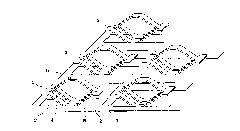
Figure 1 shows a perspective view of the spring core.
312749 - 2 -

CA 022~492 1998-12-08
Figure 2 shows a sectional diagram of the plate.
Figure 3 shows a vertical section of one embodiment of the spring core.
Figure 4 shows a vertical section of another embodiment of the spring core.
Figure 5 show a vertical section of a third embodiment of the spring core.
5 Figure 6 shows a perspective view of the embodiment of Figure 5.
DETAILED DESCRIPTION OF THE INVENTION
As Figure 1 shows, the spring core according to this invention can have a
plate (1) with the spring elements (3) pro~ ce~l from the punched passages (2),
with the spring elements being arranged symmetrically and in rows. The upper
10 spring clips (5) can be bent up out ofthe punched passages (2) in the lower spring
clips (6). This design and arrangement ofthe spring elements can yield aplurality
of leaf spring systems, where each spring element can be loaded individually.
Figure 2 shows that the spring core can have a plate (1) with punched
passages (2) to form the spring elements (3), with the upper spring clip (5) and the
15 lower spring clip (6) being formed by means of the passages (4). It can also be
seen that the dimensions ofthe spring elements may vary, as illustrated by shorter
spring element (7).
Figure 3 shows a vertical section of the spring core, formed from a plate
( 1), with the spring elements (3) extrusion-coated with foam (8) so that the interior
20 (9) of the spring elements (3) is kept free of foam, thus ~ellllilling ~lhllulll
ventilation ofthe mattress or seat cushion. FulLhellllore, open areas (10) are also
shown, pellllilLillg free longitudinal movement ofthe spring elements when a load
is applied to the spring elements.
312749 - 3 -

CA 02255492 1998-12-08
Figure 4 shows a vertical section through another embodiment, with the
individual spring elements (3) consisting of the upper spring clips (5) and the
lower spring clips (6), which are extrusion coated with foam (8) so that the interior
(9) of the spring elements (3) is kept free of foam. Therefore, the mattress is
5 flexible and ~Clllliki optimum ventilation. Open areas (10) are shown to permit
free longitudinal movement of the spring elements under load.
Figure 5 shows an embodiment ofthe spring core in which the area beneath
the lower spring clip (6) is also kept free of extruded foam, allowing additional
ventilation.
Figure 6 shows a pc,~c-;livc view ofthe embodiment shown in Figure 5,
and more clearly shows that the foam-free areas (10) between spring elements (3)can be provided on four sides of each spring element (3).
The for~,oing ~lesc~irtion of the invention is intended to be illu~L,ative and
not restrictive. Obvious variations will occur to those of skill in the art. These
variations are intended to be encomr~ese~l by the invention, which is limited only
by the scope and spirit of ~e appended claims.
312749 - 4 -

Representative Drawing
A single figure which represents the drawing illustrating the invention.
Administrative Status

2024-08-01:As part of the Next Generation Patents (NGP) transition, the Canadian Patents Database (CPD) now contains a more detailed Event History, which replicates the Event Log of our new back-office solution.

Please note that "Inactive:" events refers to events no longer in use in our new back-office solution.

For a clearer understanding of the status of the application/patent presented on this page, the site Disclaimer , as well as the definitions for Patent , Event History , Maintenance Fee  and Payment History  should be consulted.

Event History

Description Date
Inactive: IPC from MCD 2006-03-12
Time Limit for Reversal Expired 2003-12-08
Application Not Reinstated by Deadline 2003-12-08
Deemed Abandoned - Failure to Respond to Maintenance Fee Notice 2002-12-09
Inactive: Cover page published 1999-06-29
Application Published (Open to Public Inspection) 1999-06-09
Inactive: Filing certificate - No RFE (English) 1999-04-16
Request for Priority Received 1999-04-08
Inactive: Correspondence - Formalities 1999-04-08
Classification Modified 1999-02-05
Inactive: IPC assigned 1999-02-05
Inactive: First IPC assigned 1999-02-05
Letter Sent 1999-01-19
Filing Requirements Determined Compliant 1999-01-18
Inactive: Filing certificate - No RFE (English) 1999-01-18
Inactive: Applicant deleted 1999-01-14
Application Received - Regular National 1999-01-14

Abandonment History

Abandonment Date Reason Reinstatement Date
2002-12-09

Maintenance Fee

The last payment was received on 2001-11-23

Note : If the full payment has not been received on or before the date indicated, a further fee may be required which may be one of the following

  • the reinstatement fee;
  • the late payment fee; or
  • additional fee to reverse deemed expiry.

Please refer to the CIPO Patent Fees web page to see all current fee amounts.

Fee History

Fee Type Anniversary Year Due Date Paid Date
Application fee - small 1998-12-08
MF (application, 2nd anniv.) - small 02 2000-12-08 2000-12-08
MF (application, 3rd anniv.) - small 03 2001-12-10 2001-11-23
Owners on Record

Note: Records showing the ownership history in alphabetical order.

Current Owners on Record
FRANZ KUTSCHI
Past Owners on Record
None
Past Owners that do not appear in the "Owners on Record" listing will appear in other documentation within the application.
Documents

To view selected files, please enter reCAPTCHA code :


To view images, click a link in the Document Description column. To download the documents, select one or more checkboxes in the first column and then click the "Download Selected in PDF format (Zip Archive)" or the "Download Selected as Single PDF" button.

List of published and non-published patent-specific documents on the CPD .

If you have any difficulty accessing content, you can call the Client Service Centre at 1-866-997-1936 or send them an e-mail at CIPO Client Service Centre.


Document
Description 
Date
(yyyy-mm-dd) 
Number of pages   Size of Image (KB) 
Representative drawing 1999-06-25 1 14
Cover Page 1999-06-25 1 34
Abstract 1998-12-08 1 14
Claims 1998-12-08 2 61
Description 1998-12-08 4 154
Drawings 1998-12-08 4 110
Filing Certificate (English) 1999-01-18 1 163
Filing Certificate (English) 1999-04-16 1 165
Reminder of maintenance fee due 2000-08-09 1 109
Courtesy - Abandonment Letter (Maintenance Fee) 2003-01-06 1 176
Reminder - Request for Examination 2003-08-11 1 112
Correspondence 1999-01-26 1 18
Correspondence 1999-04-08 1 28
Fees 2000-12-08 1 31
Fees 2001-11-23 1 32