Note: Descriptions are shown in the official language in which they were submitted.
CA 022~739 l998-ll-20
W097/45926 PCT/SE97/00891
AN ELECTRIC HIGH VOLTAG~ AC ~T~
The present invention relates to an electric high
voltage AC machine intended to be directly connected to a
distribution or transmission network, said machine
comprising at least one winding.
Such generators with a rated voltage of up to 36 kV
is described by Paul R. Siedler, "36 kV Generators Arise
from Insulation Research", Electrical World, October 15,
1932, pp. 524-527. These generators comprise windings
formed of medium voltage insulated conductors wherein
insulation is subdivided into various layers of different
dielectric constants. The insulating material used is
formed of various combinations of the three components of
micafolium-mica, varnish and paper.
In a publication by Power Resea~ch Institute,
EPRI, EL-3391, April 1984 a generator concept is proposed
for providing such high voltages that the generator can be
directly connected to a power network without any
intermediate transformer. Such a generator was 5upposed to
comprise a superconducting rotor. The magnetization
capacity of the superconducting field would then make it
possible to use air gap windings of sufficient thickness
for withstanding the electric forces. The proposed rotor
is, however, of a complicated structure with a very thick
insulation which considerably increases the size of the
machine. In addition thereto special measures have to be
taken for insulating and cooling the coil end sections.
By electric high voltage AC machines is meant,
according to the present invention, rotating electric
machines like generators in power stations for production
of electric power, double-fed machines, outer pole
machines, synchronous machines, asynchronous converter
cascades, as well as power transformers. For connecting
such machines, except for transformers, to distribution
and transmission networks, in the following commonly
CA 022~739 1998-11-20
W097/45926 2 PCT/SE97/00891
referred to as power networks, a transformer has so far
been needed for transforming the voltage up to the network
level, that is in the range of 130-400 kV.
By manufacturing the winding of these machines of an
insulated electric high voltage conductor with a solid
insulation of similar structure as cables used for power
transmission the voltage of the machine can be increased
to such levels that the machines can be directly connected
to any power network without an intermediate transformer.
Thus this transformer can be omitted. Typical working
range for these machines is 30-800 ~V.
For this kind of machines special attention has to
be paid to grounding problems.
Grounding of generator systems and other similar
electrical systems implies intentional measures for
connecting an electric system to ground potential. When
the so-called neutral point of the system is available it
is often connected to ground, directly or through a
suitable impedance. It also happens that other points in
the system are connected to ground. If one point in the
system is grounded the complete system is grounded as long
as the galvanic connection extends.
The grounding principle used is determined by the
design of the system. For a system including a generator
directly connected to a Y-~ connected step-up-transformer
with the ~-winding at the generator voltage the following
grounding alternatives are most common.
- High resistance grounding
- No grounding
- Resonant grounding.
High resistance grounding is normally realized by
connection of a low ohmic resistor in the secondary of a
distribution transformer with the primary winding of the
transformer connected from the generator neutral point to
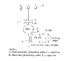
ground. Such prior art grounding is illustrated in fig. l,
which shows a generator 2 connected by a Y-~ connected
step-up trans~ormer 3 to a network 9. The primary ll of a
CA 022~739 l998-ll-20
W097/45926 3 PCT/SE97/00891
distribution transformer is connected between the neutral
point of the generator 2 and ground. In the secondary lO
of the transformer a resistor 12 is connected.
The same kind of grounding can, of course, be
obtained by installing a high ohmic resistor directly
between the generator neutral point and ground.
An ungrounded electric system lacks any intentional
connection to ground. Thus an ungrounded generator has no
connection between its neutral point and ground, except
for possible voltage transformers for feeding different
relays and instruments.
Resonant grounding is normally also realized as
illustrated in fig. l with the resistor 12 replaced by a
reactor 12a. The reactor reactance is chosen such that the
capacitive current during a line to ground fault is
neutralized by an equal component of inductive current
contributed for by the reactor 12a.
Also low resistance or low impedance grounding and
effective grounding of the above systems are possible. Low
resistance or low impedance grounding will result in lower
transient overvoltages but higher ground fault currents,
which can cause internal damages to the machine.
Low resistance grounding is achieved by the intent-
ional insertion of a resistance between the generator
neutral and ground. The resistance may be inserted either
directly in connection to ground or indirectly, in the
secondary of a transformer whose primary is connected
between generator neutral and ground, cf. fig. l.
Low impedance grounding, that is low inductance
grounding is accomplished in the same way as low
resistance grounding with the substitution of an inductor
for the resistor. The value of the inductor in ohms is
less than that required for resonant grounding, as
discussed above.
For systems comprising several generators connected
to a common feeding line or bus with circuit breakers
between the generator terminals and the common bus low
resistance or low impedance grounding is suitable.
CA 022~739 1998-11-20
W097/45926 4 PCT/~E97/00891
Effectively grounding the neutral of a generator has
substantially the same advantages and disadvantages as the
low resistance or low impedance grounding with some
differences.
A system is said to be effectively grounded if
certain impedance requirements, which restricts the size
of the grounding impedance, are fulfilled. In an
effectively grounded system the maximum phase-to-ground
voltage in unfaulted phases, in case of a ground fault,
are limited to 80~ of phase-to-phase voltage.
A power system network is mainly grounded through
ground connections of neutral points o~ transformers in
the system and can include no impedance ~except for
contact resistances), so-called direct grounding, or have
a certain impedance.
Previously known grounding techniques are described
in e.g. the publication IEEE C62.92-1989, IEEE Guide ~or
the Application of Neutral Grounding-in Electrical Utility
Systems, Part II - Grounding of Synchronous Systems,
published by the Institute of Electrical and Electronics
Engineers, New York, USA, September, l989.
If the generator neutral is grounded through a low
resistance or inductance as discussed above, a path is
formed for third harmonic currents from the generator
neutral to ground. If a directly grounded or low-impedance
grounded transformer winding or another low-impedance
grounded generator is directly connected to the generator,
the third harmonic currents will circulate therebetween
under normal conditions.
Techni~ues for solving the problems of third
harmonic currents in generator- and motor-operation of AC
electric machines of the kind to which the present
invention relates are described in Swedish patent
applications 9602078-9 and 9700347-9.
The purpose of the present invention is to provide
an electric high voltage AC machine suitable for direct
connection to distribution or transmission networks as
indicated above, which machine is provided with grounding
CA 022~739 1998-11-20
W097145926 5 PCT/SE97100891
means suitable for different uses and operating conditions
of the machine.
This purpose is obtained with an electric high
voltage AC machine of the kind defined in the introductory
portion of the description and having the characterising
features of claim l.
An important advantage of the machine according to
the invention resides in the fact that the electric field
is nearly equal to zero in the end region of the windings
outside the second layer with semiconducting properties.
Thus no electric fields need to be controlled outside the
winding and no field concentrations can be formed,
neither within the sheet, nor in winding end regions, nor
in transitions therebetween.
lS According to an advantageous embodiment of the
machine according to the invention at least two adjacent
layers have substantially equal thermal expansion
coefficients. In this way defects, cracks or the like as a
result of thermal motions in the winding, are avoided.
According to another advantageous embodiment of the
machine according to the invention said grounding means
comprise means for low resistance grounding of the
winding. In this way transient overvoltages as well as the
ground fault current can be limited to moderate values.
According to still another advantageous embodiment
of the machine according to the invention, wherein the
machine has a Y-connected winding, the neutral point of
which being available, high resistance grounding means
comprise a resistor connected in the secondary of a
transformer whose primary is connected between the neutral
point and ground. In this way the resistor used in the
secondary of the transformer is of comparatively low ohmic
value and of rugged construction. Sufficient damping to
reduce transient overvoltages to safe levels can be
achieved with a properly sized resistor. Further,
mechanical stresses and fault damages are limited during
line-to-ground faults by the restriction of the fault
current. Such a grounding device is also more economical
CA 022~739 1998-ll-20
W097/4S926 6 PCT/SE97/00891
than direct insertion of a high ohmic resistor between the
generator neutral and ground.
According to another advantageous embodiment of the
machine according to the invention, wherein the machine
has a Y-connected winding the neutral point of which being
available, the grounding means comprises a reactor
connected in the secondary of a transformer whose primary
is connected between the neutral point and ground, said
reactor having characteristics such that the capacitive
current during a ground ~ault is substantially neutralized
by an equal component of inductive current contributed for
by the reactor. ~n this way the net fault current is
reduced to a low value by the parallel resonant circuit
thus formed, and the current is essentially in phase with
the fault voltage. The voltage recovery on the faulted
phase is very slow in this case and accordingly any ground
fault of a transient nature will automatically be
extinguished in a resonant grounded system.
According to still other advantageous embodiments of
the machine according to the invention the grounding means
comprise a Y-~ grounding transformer or a so-called zigzag
grounding transformer connected to the network side of the
machine. The use of such grounding trans~ormers are
equivalent to low inductance or low resistance grounding
with respect to fault current levels and transient
overvoltages.
To explain the invention in more detail embodiments
of the machine according to the invention, chosen as
examples, will now be described more in detail with
reference to fig. 2-ll on the accompanying drawings on
which
~ig. l illustrates prior art grounding of a synchronous
generator,
fig. 2 shows an example of the insulated conductor used in
the windings of the machine according to the invention,
fig. 3 shows an ungrounded three-phase machine in the form
of a Y-connected generator or motor connected to a power
system,
CA 022~739 l998-ll-20
W097/4S926 7 PCT/SE97/00891
fig. 4-13 show different examples of grounding the Y-
connected machine in fig. 3,
fig. 14 shows a machine according to the invention in the
form of a ~-connected generator or motor connected to a
power system, and
flg. 15 illustrates the use of a grounding transformer in
the system shown in fig. 14.
In fig. 2 an example is shown of an insulated
conductor, which can be used in the windings o~ the
machine according to the invention. Such an insulated
conductor comprises at least one conductor 4 composed of a
number of non-insulated and possibly insulated strands 5.
Around the conductor 4 there is an inner semiconducting
layer 6, which is in contact with at least some of the
non-insulated strands 5. This semiconducting layer 6 is in
its turn surrounded by the main insulation of the cable in
the form of an extruded solid insulating layer 7. The
insulating layer is surrounded by an external semiconduct-
ing layer 8. The conductor area of the cable can vary
between 80 and 3000 mm and the external diameter of the
cable between 20 and 250 mm.
Fig. 3 shows schematically an ungrounded electric
high voltage AC machine in the form of a Y-connected
generator or motor 14 directly connected to a power system
16.
Fig. 4 shows grounding means in the form of an
overvoltage protector, like a non-linear resistance
arrester 18, connected between the neutral point 20 of the
Y-connected machine 14 and ground. Such a non-linear
resistance arrester 18 connected to the neutral point
protects the insulated conductor used in the machine
windings against transient overvoltages, such as
overvoltages caused by a stroke of lightning.
Fig. 5 shows an embodiment with a high ohmic
resistor 22 connected in parallel to the non-linear
resistance arrester 18. The non-linear resistance
arrester 18 is functioning in the same way in this
embodiment as in the embodiment shown in fig. 4 and with
CA 022jj739 1998-11-20
W097/45926 8 PCT/SE97/00891
the resistor 22 a sensitive detection of ground faults by
measuring the voltage across the resistor 22 is realised.
Fig. 6 shows an embodiment with high resistance
grounding of the neutral point 20. In this embodiment a
technique similar to the prior art described in connection
with fig. l is used. Thus a resistor 24 is connected to
the secondary 26 of a transformer with the primary winding
28 of the transformer connected from the neutral point 20
of the machine 14 to ground. The resistor 24 is
comparatively low ohmic and of rugged construction, as
compared to a high ohmic resistor which would be needed
for direct connection between the neutral point 20 and
ground for obtaining the same result. The voltage class of
the resistor can consequently be reduced. Also in this
case a non-linear resistance arrester 18 is connected in
parallel to the primary winding 28. With this embodiment
mechanical stresses and fault damages are limited during
line-to-ground faults by restricting the fault current.
Transient overvoltages are limited to safe levels and the
grounding device is more economical than direct insertion
of a resistor.
Resonant grounding of the machine can be realised in
a similar way by replacing the resistor 24 by a reactor
having characteristics such that the capacitive current
during a line-to-ground fault is neutralized by an equal
component of inductive current contributed for by the
reactor. Thus the net fault current is reduced by the
parallel resonant circuit thus formed and the current will
be essentially in phase with the fault voltage. After
extinction of the fault the voltage recovery on the
faulted phase wil be very slow and determined by the
ratio of inductive reactance to the effective resistance
of the transformer/reactor combination. Accordingly any
ground fault of transient nature will automatically be
extinguished in such a resonant grounded system. Thus such
resonant grounding means limits the ground fault current
to practically zero, thus minimising the mechanical
stresses. Further continued operation of the machine can
CA 022~739 1998-11-20
W097/45926 9 PCT/SE97/00891
be permitted after the occurrence o~ a phase-to-ground
fault until an orderly shutdown can be arranged.
Fig. 7 shows an embodiment with a non-linear
resistance arrester 18 connected between the neutral point
20 and ground and a grounding transformer 30 connected on
the network side of the machine 14. The grounding
transformer 30 is of Y-~ design with the neutral point of
the Y-connection connected to ground, whereas the ~-
winding is isolated. Grounding transformers are normally
used in systems which are ungrounded or which have a high
impedance ground connection. As a system component the
grounding transformer carries no load and does not affect
the normal system behaviour. When unbalances occur the
grounding transformer provides a low impedance in the zero
sequence network. The grounding transformer is in this way
equivalent to a low inductance or low resistance grounding
with respect to fault current levels and transient
overvoltages.
The grounding transformer can also be a so-called
zigzag trans~ormer with special winding arrangements, see
e.g. Paul M. Anderson, "Analysis of Faulted Power
Systems~, The Iowa State University PresstAmesr 1983, pp.
255-257.
Also a possible auxiliary power transformer can be
used ~or such grounding purposes.
Fig. 8 shows an embodiment with a low ohmic resistor
32 connected between the neutral point 20 of the machine
14 and ground. The main advantage of such a low resistance
grounding is the ability to limit transient and temporary
overvoltages. The currents will, however, be higher in
case of single phase ground faults. Also third harmonic
currents will be higher in undisturbed operation.
Fig. 9 shows an alternative embodiment of the
machine according to the invention in which the resistor
32 is replace~ by a low inductance inductor 34 connected
between the neutral point 20 and ground. Low inductance
grounding works essentially in the same way as low ohmic
grounding The value of the inductor 34 in ohms is less
CA 022jj739 1998-11-20
W097/45926 lO PCT/SE97/00891
than that required ~or resonant grounding, cf. description
of fig. 6.
As an alternative to the direct connection between
the neutral point 20 and ground of the resistor 32 or the
inductor 34, they may be indirectly connected with the aid
of a transformer whose primary is connected between the
neutral point 20 and ground and whose secondary contains
the resistor or inductor, cf. the description of fig. 6.
In ~ig. lO an embodiment is shown comprising two
impedances 36 and 38 connected in series between the
neutral point 20 of the machine 14 and ground, the
impedance 36 having a low impedance value and the
impedance 38 a high impedance value. The impedance 33 can
be short-circuited by a short-circuiting device 40. In
normal operation the short-circuiting device 40 is open in
order to ~;nim~ ze third harmonic currents. In case of a
ground fault the short-circuiting device 40 is controlled
to short-circuit the impedance 38 and the potential in the
neutral point 20 will be low and the current to ground
comparatively high.
In case o~ an internal ground fault in the machine
14 the impedance 38 is not short-circuited. As a
consequence the voltage will be high in the neutral point
20 but the current to ground will be limited. In such a
situation this is to prefer since a high current can give
rise to damages in this case.
To be able to cope with the problems arising from
third harmonics when directly connecting an AC electric
machine to a three-phase power network, i.e. when no step-
up transformer is used between the machine and thenetwor~, grounding means in the ~orm of a suppression
~ilter 35, 37, tuned to the third harmonic together with
an overvoltage protector 39 can be used, see fig. ll. The
filter thus comprises a parallel resonance circuit
consisting of an inductor 35 and a capacitive reactance
37. The dimensioning of the filter 35, 37 and its
overvoltage protector 39 is such that the parallel circuit
is capable of absorbing third harmonics from the machine
CA 022~739 1998-11-20
W097/45926 11 PCT/SE97/00891
14 during normal operation, yet limiting transient and
temporary overvoltages. In case of a fault the overvoltage
protector 39 will limit the fault voltage such that the
fault current flows through the overvoltage protector 39
if the fault is considerable. In case of a single-phase
ground fault the currents will be higher as compared to
e.g. the case of high resistance grounding since the
fundamental impedance is low.
In fig. 12 an embodiment is shown wherein the
grounding means comprises a detuned switchable third
harmonics depression filter connected in parallel to an
overvoltage protector 40. Such filters can be realised in
several different ways. Fig. 12 shows an example
comprising two inductors 42, 44 connected in series and a
capacitor 46 connected in parallel to the series-
connected inductors 42, 44. Further a short-circuiting
device 48 is connected across the inductor ~4.
The short-circuiting device 48 is controllable to
change the characteristic of the filter by short-
circuiting the inductor 44 when a risk for third harmonicresonance between the filter and the machine 14 and
network 16 is detected. This is described more in detail
in Swedish patent application 9700347-9. In this way third
harmonic currents are strongly limited in normal
operation. Transient and temporary overvoltages will be
limited and the currents will ~e higher in case of a
single-phase ground fault in the same way as described in
connection with fig. 11.
Fig. 13 shows an embodiment wherein the neutral
point 20 of the machine 14 is directly connected to
ground, at 21. Such direct grounding limits transient and
temporary overvoltages but results in high currents in
case of ground faults. Third harmonic current flow from
the neutral 20 of the machine to ground will be
comparatively high in normal operation.
As a further alternative the grounding means of the
machine according to the invention can comprise an active
CA 022~739 l998-ll-20
W097/45926 12 PCT/SE97/00891
circuit for providing a connection of the neutral point to
ground having desirable impedance properties.
In fig. 14 a a-connected three-phase machine 50 is
shown directly connected to the distribution or
transmission network 16.
In such a situation a grounding transformer of the
same kind as the one used in the embodiment shown in fig.
7 can be connected on the network side of the machine 50.
As in the embodiment of fig. 7 the grounding
transformer can be a Y-a-connected transformer with the
neutral point of the Y-connection ground, or a so called
zigzag grounding transformer, that is a Z-0-connected
transformer with the Z grounded. The grounding transformer
will limit temporary overvoltages.
lS As in the embodiment of fig. 7 a possible auxiliary
power transformer can also be used for this purpose.