Language selection

Search

Patent 2255869 Summary

Third-party information liability

Some of the information on this Web page has been provided by external sources. The Government of Canada is not responsible for the accuracy, reliability or currency of the information supplied by external sources. Users wishing to rely upon this information should consult directly with the source of the information. Content provided by external sources is not subject to official languages, privacy and accessibility requirements.

Claims and Abstract availability

Any discrepancies in the text and image of the Claims and Abstract are due to differing posting times. Text of the Claims and Abstract are posted:

  • At the time the application is open to public inspection;
  • At the time of issue of the patent (grant).
(12) Patent: (11) CA 2255869
(54) English Title: LOCAL COMPONENT-SPECIFIC CONSOLE
(54) French Title: CONSOLE SPECIFIQUE AUX COMPOSANTES LOCALES
Status: Expired and beyond the Period of Reversal
Bibliographic Data
(51) International Patent Classification (IPC):
  • H04Q 01/20 (2006.01)
  • H04M 03/22 (2006.01)
  • H04M 03/24 (2006.01)
  • H04Q 01/24 (2006.01)
  • H04Q 09/00 (2006.01)
(72) Inventors :
  • STOVALL, GREGORY T. (United States of America)
  • MCKNIGHT, DAVID WESLEY (United States of America)
(73) Owners :
  • NORTEL NETWORKS LIMITED
(71) Applicants :
  • NORTEL NETWORKS LIMITED (Canada)
(74) Agent: GOWLING WLG (CANADA) LLP
(74) Associate agent:
(45) Issued: 2004-03-02
(22) Filed Date: 1998-12-07
(41) Open to Public Inspection: 1999-06-11
Examination requested: 2000-10-30
Availability of licence: N/A
Dedicated to the Public: N/A
(25) Language of filing: English

Patent Cooperation Treaty (PCT): No

(30) Application Priority Data:
Application No. Country/Territory Date
08/988,685 (United States of America) 1997-12-11

Abstracts

English Abstract


A system and method for remotely monitoring and controlling signals
to or from a component in a central office switching system having many
components, such as line cards. The component reports status signals to a
processing facility, which receives the status signals and broadcasts them to
a device located in the central office. The device, upon receiving the
broadcasted signals, displays the status signals so that a user can thereby
monitor the component.


Claims

Note: Claims are shown in the official language in which they were submitted.


What is claimed is:
1. A method for monitoring an output of a component in a switching system, the
method comprising the steps of:
reporting the output and an identifier of the component to a central
processing
facility;
receiving the output and identifier at the central processing facility;
broadcasting the output and identifier to a personal digital assistant from
the
central processing facility;
receiving the output and identifier at the personal digital assistant;
displaying the output on the personal digital assistant and identifying the
component from a group of components with the identifier; and
determining the location of the personal digital assistant relative to the
location of the component,
whereby the personal digital assistant can receive the output and identifier
of
the component regardless of the personal digital assistant's proximity to the
component.
2. The method of claim 1 further comprising:
broadcasting a location of the component to the personal digital assistant;
and
receiving the location at the personal digital assistant.
3. The method of claim 2 further comprising displaying the location of the
component on the personal digital assistant.
4. The method of claim 2 further comprising:
reporting the location of the component to the central processing facility;
and
receiving the location of the component at the central processing facility.
5. The method of claim 1 wherein the output designates a status of the
component.

6. The method of claim 1 wherein the output is reported using wireless
communications.
7. The method of claim 1 wherein the output is reported using an existing data
network.
8. The method of claim 1 wherein the output is reported using a dedicated data
network.
9. The method of claim 1 wherein the output is broadcasted using wireless
communications.
10. The method of claim 1 wherein the output is broadcasted using an existing
data network.
11. The method of claim 1 wherein the output is broadcasted using a dedicated
data network.
12. A system for monitoring an output of a component in a switching system
having a central processing facility, the system comprising:
means for reporting the output to the central processing facility;
means for receiving the output at the central processing facility;
means for broadcasting, in realtime, the output and the location of the
component to a personal digital assistant whether the personal digital
assistant is
located near to or far from the component;
means for receiving, in realtime, the output and the location of the component
at the personal digital assistant;
means for displaying the output on the personal digital assistant; and
means for determining the location of the personal digital assistant relative
to
the location of the component.
13. The system of claim 12 wherein the output designates a status of the
component.
9

14. The system of claim 12 wherein the means for reporting uses wireless
communications.
15. The system of claim 12 wherein the means for reporting uses an existing
data
network.
16. The system of claim 12 wherein the means for reporting uses a dedicated
data
network.
17. The system of claim 12 wherein the means for broadcasting uses wireless
communications.
18. The system of claim 12 wherein the means for broadcasting uses an existing
data network.
19. The system of claim 12 wherein the means for broadcasting uses a dedicated
data network.
20. The system of claim 12 further comprising means for displaying the
location
of the component on the personal digital assistant.
21. The system of claim 12 further comprising:
means for reporting the location of the component to the central processing
facility; and
means for receiving the location of the component at the central processing
facility.
22. A system for monitoring a plurality of components in a central office, the
plurality of components reporting status information to a processing facility
of the
central office, the system comprising:
a broadcasting system for providing the status of a first and second component
to a personal digital assistant located near the first component, and where
the personal
digital assistant is separate from the processing facility and separate from
the second
10

component;
a receiver connectable to the personal digital assistant for receiving the
status;
a transmitter connectable to the personal digital assistant for transmitting a
code to control the first component;
a locator connectable to the personal digital assistant for determining the
location of the personal digital assistant relative to the location of the
first component
and the location of the second component.
23. The system of claim 22 wherein the broadcasting system uses wireless
communications.
24. The system of claim 22 wherein the code is transmitted to the processing
facility and wherein the processing facility controls the first component in
response to
the code.
25. The system of claim 22 wherein the broadcasting system also provides a
location of the first component to the personal digital assistant.
11

Description

Note: Descriptions are shown in the official language in which they were submitted.


CA 02255869 2003-09-19
LOCAL COMPONENT-SPECIFIC CONSOLE
Technical Field
This invention relates generally to switching systems, and in
particular, to a system and method for remotely monitoring and/or
controlling signals to and from a component in the switching system.
Background of the Invention
A conventional public switched telephone network ("PSTN") is formed
by routing trunks or lines between various switching systems. The
switching systems are often physically grouped together to form a central
office. A central once may connect any combination of lines and trunks,
and therefore can by used in local switching systems (for interconnecting
lines and trunks) and network switching systems (for interconnecting
trunks). For purposes of simplicity, only a local switching system for
interconnecting lines and trunks will be further discussed.
Often, a single central once switches literally hundreds or thousands
of lines. The central off ce therefore must arrange the switching hardware
in a logical manner so that it may be readily accessed, serviced, or replaced.
A typical central off ce will be housed in a multi-floor building, each floor
.
including several rows of switch frames, each switch frame including several
shelves of line cards, and each line card serving multiple lines.
A typical central office also contains a central processing facility, or
management console. The management console controls the operation of
the equipment in the central off ce, including the frames and line cards
-1-

CA 02255869 1998-12-07
Attorney Docket No. RR-2252
stored therein. For example, the management console may show certain
status indicators for an individual line card that inform a technician as to
how the card is working or if it is working properly. In this example, an
error has occurred in a particular line card. The technician first goes to the
management console to view the status indicators and determine the faulty
line card. The technician then finds the line card, performs corrective
maintenance thereon, and returns to the management console to verify that
the line card is working as desired.
To avoid requiring the technician to run back and forth between the
line card and the management console, two technicians typically work
together, one at the line card and one at the management console, and
communicate via radio or other conventional means. This solution is
undesirable due to the high labor cost of the two technicians. Also, this
solution is inherently prone to errors due by communication failures.
l~ Instead, what is needed is a system and method that allows a technician to
monitor the status indicators that normally appear on the maintenance
console, while working on the line card or other switch component.
Summary of the Invention
The foregoing problems are solved and a technical advance is
achieved by a system and method for remotely monitoring and controlling
signals to or from a component in a switching system such as a central
office. In one embodiment, the central office has many components, such as
line cards, and a processing facility. One of the components reports status
signals to the processing facility, which receives the status signals and
broadcasts them to a device located in the central office. The device, upon
receiving the broadcasted status signals, displays the status signals so that
a user can thereby monitor the component.
In another embodiment, the processing facility also broadcasts a
location signal to the device, the location signals being used to find the
-2-

CA 02255869 1998-12-07
Attorney Docket No. RR-2252
component. The device, upon receiving the broadcasted location signals,
displays them as well, so that the user can easily find or identify the
component.
In yet another embodiment, the device can also send a code to the
processing facility. The code is used to control the component, through the
processing facility.
Brief Description of the Drawings
Fig. 1 illustrates an exemplary, simplified central office.
Fig. 2 illustrates a personal digital assistant used to display status
and/or location information for a component of the central office of Fig. 1.
Fig. 3 is a flow chart of a routine performed to supply the status
and/or location information to the personal digital assistant of Fig. 2.
Fig. 4 is an exemplary display output of the personal digital assistant
of Fig. 2.
1 ~ Description of the Preferred Embodiment
Referring to Fig. 1, the reference numeral 10 designates a central
office for utilizing one embodiment of the present invention. The central
office 10 includes two floors 12, 14, each of which includes two rows 12A,
12B, and 14A, 14B, respectively, of frames 16a - 161. Each of the frames
16a - 16l are similarly configured, as shown by representative frame 16a,
having two shelves 18a and 18b, each having three line cards 20a, 20b, 20c
and 22a, 22b, 22c, respectively.
The central office 10 also includes several low power spread-spectrum
transmitters 30, 32, 34, 36, 38. The transmitters are strategically placed
throughout the central office 10 so that each line card of each frame 16a -
16l can receive signals from at least three of the transmitters. The
transmitters 30-38 are all tightly synchronized, with each transmitter
emitting a unique signal. The signals are similar to the signals provided
-3-

CA 02255869 2003-04-22
Attorney Docket No. RR-2252
by global positioning satellites, thereby providing any receiver with at least
three signals to triangulate its enact location. It is understood that the
placement of the transmitters is subject to unique RF characteristics of the ~-
central office 10, which can be readily determined by one of ordinary skill in
the art.
The central office 10 also includes a central processing facility 40 for
receiving and processing, among other things, location information and
status information from each of the line cards. In one embodiment, the
central processing facility 40 is a computer that receives the location and
status information through a data bus 42 connected to each of the Line
cards. It is understood, however, that the functionality of the central
processing facility may be distributed through one or more devices. Also,
the data bus 42 may represent a bus, such as an Ethernet bus, dedicated for
the functions described herein, or available bandwidth on an existing bus.
1 ~ In another embodiment, the central processing facility 40 receives the
location through a radio frequency (RF) receiver antenna 44. The central
processing facility 40 also includes an RF transmitter 46 for transmitting
various signals and information, as discussed in greater detail, below.
Because of the multiplicity of components in the central office 10, it is
often very difficult to find a particular line card to access, service, or
replace. This problem has been addressed in U.S. Patent
No. 6,047,193 entitled "System and Method for Locating a Switch Component",
filed
November 12,1997.
Therefore, each component can determine its location and transmit it to the
central
processing facility 40. In addition, each component reports status information
to
the central processing facility 40.
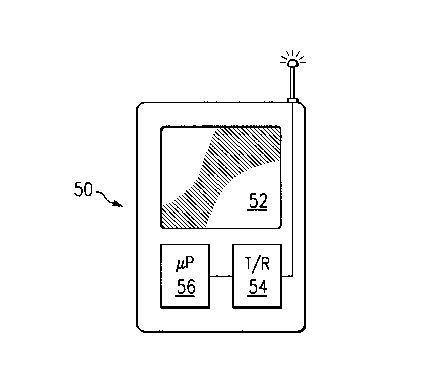
Referring to Fig. 2, the reference numeral 50 designates a personal
computer, or digital assistant, hereinafter "PDA". The PDA 50 may be a
-4-

CA 02255869 2003-04-22
Attorney Docket No. RR-2252
commercially available PDA, such as a NE~rVTON computer by Apples
Computer, Inc. of Cupertino, CA. Alternatively, the PDA 50 may be a
simple display, such as a liquid crystal display, with a limited amount of --
processing capabilities. The PDA 50 includes a monitor 52, an RF
transmitter/receiver 54, and a controller 56. In an alternative embodiment,
the RF transmitter/receiver 54 may be a data port (not shown) connectible
to a data bus on the frame 16a. Also, the PDA 50 includes a hook (not
shown) so that it can be attached to a frame. The PDA 50 can therefore be
used by a technician or user in conjunction with the central processing
facility 40 to work on a frame or line card, as described in greater detail
below.
Referring to Fig. 3, a method 100 is used to facilitate repair of a
component in the central once 10. For the sake of example, the line card
22a of frame 16a will be found, diagnosed, and repaired. At step 110, the
line card 22a reports status information to the central processing facility 40
that indicates that the line card 22a needs attention. Alternatively, the
central processing facility 40 may deduce that the line card 22a needs
attention, such as by noticing that the line card is no Ionger communicating
or by a scheduled maintenance timer. At step 112, the line card 22a reports
its location information to the central processing facility 40. Alternatively,
such as when the line card 22a is no longer communicating, the central
processing facility 40 previously stored location information for the Iine
card.
At step 114, the central processing facility 40 reports the location
information to the PDA 50. In the preferred embodiment, the central
processing facility 40 converts the location information to a physical
location
that can be easily used by an individual. For example, Iine card 22a can be
mapped to:
(floor 1, row 1, frame 1, shelf 1, card 1).
('~ trademark)
-5-

CA 02255869 1999-O1-06
Attorney Docket No. RR-222
In this way, a user having the PDA 50 can locate the line card 22a.
Although not shown, in alternative embodiments, the PDA 50 may include
the necessary hardware and software to report to the central processing -
facility its location information so that the central processing facility may
provide relative location information (e.g., "down two floors"). In yet
another alternative embodiment, the PDA, in combination with the location
information, can deduce its own physical and/or relative location
information.
Upon finding the line card 22a, the user may request the status
information to be supplied to the PDA 50 at step 116. This step may be
accomplished in one of various ways. For one, either the PDA 50 or the
central processing facility 40 may realize that the PDA and line card 22a
are in close proximity. For another, the user may signal the PDA 50 or
central processing facility 40 by pressing a key (not shown) on the PDA, on
l~ the frame 16a, or on the line card 22a. At step 118, the central processing
facility 40 begins to transmit the status information to the PDA 50. The
user may thereby perform maintenance on the line card 22a while observing
the status information. Steps 116 and 118 may be repeated throughout the
maintenance process.
Referring to Fig. 4, in an alternative embodiment, both the status
information and the location information are simultaneously provided to the
PDA 50, as illustrated on the monitor 52. For example, the user may attach
the data port of the PDA 50 to a bus (not shown) at the frame 16a. The
central processing facility, through the bus, then notifies the PDA 50 which
2~ line card 22a is in need of repair and also reports the corresponding
status
information. In yet another alternative embodiment, only the status
information is provided.
Although illustrative embodiments of the invention have been shown
and described, other modifications, changes, and substitutions are intended
-6-

CA 02255869 1998-12-07
Attorney Docket No. RR-2252
in the foregoing disclosure. For example, the above described embodiment
can be easily implemented in different components besides line cards.
Accordingly, it is appropriate that the appended claims be construed broadly-
and in a manner consistent with the scope of the invention.

Representative Drawing
A single figure which represents the drawing illustrating the invention.
Administrative Status

2024-08-01:As part of the Next Generation Patents (NGP) transition, the Canadian Patents Database (CPD) now contains a more detailed Event History, which replicates the Event Log of our new back-office solution.

Please note that "Inactive:" events refers to events no longer in use in our new back-office solution.

For a clearer understanding of the status of the application/patent presented on this page, the site Disclaimer , as well as the definitions for Patent , Event History , Maintenance Fee  and Payment History  should be consulted.

Event History

Description Date
Time Limit for Reversal Expired 2006-12-07
Inactive: IPC from MCD 2006-03-12
Inactive: Adhoc Request Documented 2006-02-23
Letter Sent 2005-12-07
Grant by Issuance 2004-03-02
Inactive: Cover page published 2004-03-01
Pre-grant 2003-12-16
Inactive: Final fee received 2003-12-16
Notice of Allowance is Issued 2003-09-29
Letter Sent 2003-09-29
Notice of Allowance is Issued 2003-09-29
Inactive: Received pages at allowance 2003-09-19
Inactive: Office letter 2003-07-02
Inactive: Approved for allowance (AFA) 2003-06-20
Amendment Received - Voluntary Amendment 2003-04-22
Inactive: S.30(2) Rules - Examiner requisition 2002-10-21
Amendment Received - Voluntary Amendment 2001-08-20
Letter Sent 2000-11-30
Request for Examination Requirements Determined Compliant 2000-10-30
All Requirements for Examination Determined Compliant 2000-10-30
Request for Examination Received 2000-10-30
Letter Sent 1999-07-22
Inactive: Cover page published 1999-07-01
Application Published (Open to Public Inspection) 1999-06-11
Inactive: Correspondence - Formalities 1999-02-23
Inactive: First IPC assigned 1999-02-09
Classification Modified 1999-02-09
Inactive: IPC assigned 1999-02-09
Inactive: Filing certificate - No RFE (English) 1999-01-28
Inactive: Correspondence - Formalities 1999-01-19
Application Received - Regular National 1999-01-18
Amendment Received - Voluntary Amendment 1999-01-06

Abandonment History

There is no abandonment history.

Maintenance Fee

The last payment was received on 2003-11-26

Note : If the full payment has not been received on or before the date indicated, a further fee may be required which may be one of the following

  • the reinstatement fee;
  • the late payment fee; or
  • additional fee to reverse deemed expiry.

Patent fees are adjusted on the 1st of January every year. The amounts above are the current amounts if received by December 31 of the current year.
Please refer to the CIPO Patent Fees web page to see all current fee amounts.

Fee History

Fee Type Anniversary Year Due Date Paid Date
Registration of a document 1998-12-07
Application fee - standard 1998-12-07
Request for examination - standard 2000-10-30
MF (application, 2nd anniv.) - standard 02 2000-12-07 2000-12-07
MF (application, 3rd anniv.) - standard 03 2001-12-07 2001-11-09
MF (application, 4th anniv.) - standard 04 2002-12-09 2002-12-03
MF (application, 5th anniv.) - standard 05 2003-12-08 2003-11-26
Final fee - standard 2003-12-16
MF (patent, 6th anniv.) - standard 2004-12-07 2004-11-26
Owners on Record

Note: Records showing the ownership history in alphabetical order.

Current Owners on Record
NORTEL NETWORKS LIMITED
Past Owners on Record
DAVID WESLEY MCKNIGHT
GREGORY T. STOVALL
Past Owners that do not appear in the "Owners on Record" listing will appear in other documentation within the application.
Documents

To view selected files, please enter reCAPTCHA code :


To view images, click a link in the Document Description column (Temporarily unavailable). To download the documents, select one or more checkboxes in the first column and then click the "Download Selected in PDF format (Zip Archive)" or the "Download Selected as Single PDF" button.

List of published and non-published patent-specific documents on the CPD .

If you have any difficulty accessing content, you can call the Client Service Centre at 1-866-997-1936 or send them an e-mail at CIPO Client Service Centre.

({010=All Documents, 020=As Filed, 030=As Open to Public Inspection, 040=At Issuance, 050=Examination, 060=Incoming Correspondence, 070=Miscellaneous, 080=Outgoing Correspondence, 090=Payment})


Document
Description 
Date
(yyyy-mm-dd) 
Number of pages   Size of Image (KB) 
Representative drawing 1999-06-24 1 8
Description 2003-04-21 7 322
Claims 2003-04-21 4 120
Description 2003-09-18 7 314
Drawings 1999-01-18 2 43
Description 1999-01-05 7 322
Abstract 1998-12-06 1 18
Description 1998-12-06 7 329
Claims 1998-12-06 4 126
Drawings 1998-12-06 3 56
Courtesy - Certificate of registration (related document(s)) 1999-01-28 1 115
Filing Certificate (English) 1999-01-27 1 163
Reminder of maintenance fee due 2000-08-07 1 109
Acknowledgement of Request for Examination 2000-11-29 1 180
Commissioner's Notice - Application Found Allowable 2003-09-28 1 159
Maintenance Fee Notice 2006-01-31 1 172
Correspondence 1999-02-01 1 27
Correspondence 1999-01-18 3 66
Correspondence 1999-02-22 1 23
Correspondence 2000-11-30 1 26
Fees 2002-12-02 1 30
Correspondence 2003-09-18 2 81
Fees 2001-11-08 1 24
Correspondence 2003-12-15 1 32
Fees 2000-12-06 1 28
Correspondence 2006-03-01 2 127