Note: Descriptions are shown in the official language in which they were submitted.
CA 022~6061 1998-12-11
AUTOMATIC DIRECTORY NUMBER LOCATION IDENTIFICATION
FIELD OF THE INVENTION
This invention relates to a system and method for
providing telephone subscribers with information pertaining to
the location of a called party or a calling party.
BA~KGROUND OF THE INVENTION
The delivery of location information (name of
country, city, street address, etc.) to a public safety
answering point (PSAP) in a 911 system is well known.
Generally, call distribution arrangements for 911 systems
include Automatic Number Identification (ANI), and Automatic
Location Identification (ALI) being used to identify and
display information pertaining to the calling party. With ANI,
a 911 dispatcher receives a visual display of the telephone
number associated with the telephone of the calling party.
This information is transmitted to the PSAP over special ANI
trunks. The ANI is in turn used as a key to a record in an ALI
database. That record contains extended calling party
information, including street address. As such, the dispatcher
also receives a visual display of the name and address
associated with the calling party. Clearly, the extra
information aids in promptly responding to an emergency.
However, with the added benefits of 911 and Enhanced 911
systems comes substantial costs. A dedicated infrastructure,
including switches, trunks, databases, and customer equipment
is required for the storage, transmission and display of street
address information concerning a calling party. Apart from 911
systems, there have been no systems developed to date capable
of delivering location information concerning a calling party
(or a called party) to an end user. Due to the cost involved,
it is prohibitively expensive to use the 911 infrastructure to
deliver location information in the context of a non-emergency
CA 02256061 1998-12-11
call placed on the Public Switched Telephone Network (PSTN).
Caller ID service, calling number delivery service,
calling line identification, directory number, and calling
party identification are terms used interchangeably to refer to
a telephone service which identifies the directory number of
the calling party to the called party. End users subscribing
to Caller ID must purchase a "number identification device"
which is connected to a network jack and then to an end user's
Customer Premises Equipment (CPE) (typically a telephone
terminal). Some CPEs include scrollable display screens for
displaying caller ID information. These devices are designed
to display the calling party's telephone number between the
first and second ring via common channel signalling technology
such as the Custom Local Area Signalling Services/Call
Management Services (CLASS/CMS) protocol. Unlike traditional
telephones, CLASS/CMS CPEs incorporate a display and an
internal modem to enable reception of call information from a
local switch comprising part of the Public Switched Telephone
Network (PSTN). CLASS/CMS CPEs can also be used to display
other information to end users, such as the name of the calling
party. These screen-based telephone sets generally conform to
Bellcore document GR-30-CORE, "LSS-Voiceband Data Transmission
Interface", Section 6.6, Issue 1, Dec 1994. Telephone sets
supporting the ISDN access protocol conform to GR-2824-CORE
Generic Requirements for Integrated Customer Advanced
Networking (ICAN) Calling Number Identification (ICAN CNIS).
The aforementioned documents are incorporated herein by
reference. Though such CPEs are used to display a wide variety
of information, they have not to date been used to display
location information (name of country, city, street address,
etc.) about a calling party or called party.
The Advanced Intelligent Network (AIN) environment is
CA 022~6061 1998-12-11
an infrastructure proposed by Bellcore which is being put in
place and used by exchange carriers to deploy new services
quickly and effectively. The AIN infrastructure simplifies the
design and implementation of new telecommunication services by
defining a set of network elements, messages and call models.
This allows for many services to be constructed using these
standard building blocks and deployed quickly and effectively
to end users. The AIN architecture is outlined by Berman et al
in the ICC '91 proceedings, Volume 2 at pages 21.1.1 to 21.1.5,
June 1991. The contents of this publication are incorporated
herein by reference. While AIN call models have provided for
the delivery of call name and number information, none of the
existing AIN call models provides for the delivery of location
information to the calling party or to the called party.
In an AIN environment, the delivery of display
information to an end user is not only unidirectional. Whereas
CLASS/CMS features have typically been used to only deliver
call information to a called party, there have been recent
advances in the art which permit the delivery of call
information to a calling party prior to completion of the call.
One example of this advance in the art is previously filed,
commonly owned, United States patent application entitled
"DELIVERY OF DISPLAY INFORMATION TO THE CALLER IN AN ADVANCED
INTELLIGENT NETWORK", Ser. No. 08/773,494, filed on Dec. 23,
1996, in the name of Tessler et al, and the said application is
incorporated herein by reference. In one embodiment, a request
message is sent from an SSP over the SS#7 signalling network to
an SCP where a database for the required service is resident.
The SCP maps the number dialled along with calling party's
number to the information that is to be displayed and retrieves
this information from its database. The SCP then formulates
the appropriate response message and returns the message to the
CA 022~6061 1998-12-11
SSP. Once the message reply is received by the SSP, the SSP
decodes the message and delivers the display information to the
calling party. Depending on the configuration of the end
user's terminal, the call then either proceeds with or without
confirmation. In a second embodiment, call information is
provided to the calling party in the same manner described
above, except that there is no call associated with the calling
party's request for information.
In the disclosure of the aforementioned patent
application, relevant information that is stored at the SCP for
delivery to the calling party includes the name of the called
party, rate information for toll or metered calls, marketing
and promotional messages, time of day, and date. However,
relevant information does not include location information
(name of country, city, street address, etc.) concerning either
the calling party or the called party.
The delivery of location information (name of
country, city, street address, etc.) has taken on added
importance with the passage of the Telecommunications Act ("the
Act") of 1996. Among other things, the Act requires that
Incumbent Local Exchange Carriers (ILEC) the regulated entity
that owns and administers an existing access network provide to
any requesting telecommunications carrier (hereinafter referred
to as "Competing Local Exchange Carriers" (CLEC))
nondiscriminatory access to network elements on an unbundled
basis to allow CLECs to combine such network elements in order
to provide telecommunications service to end users. As well,
ILECs have a duty to provide to CLECs interconnection with
their network for the transmission and routing of telephone
exchange service and exchange access. The interconnection
contemplated by the Act provides nondiscriminatory access or
interconnection to such services or information as are
CA 02256061 1998-12-11
necessary to allow the requesting CLEC to implement local
dialling parity, including nondiscriminatory access to
telephone numbers, operator service, directory assistance, and
directory listing, with no unreasonable dialling delays.
One of the central requirements of the Act is section
251(b), namely to "provide, to the extent technically feasible,
number portability" in accordance with Federal Communication
Commission (FCC) requirements. On June 27, 1997, the FCC
adopted rules on local number portability (LNP). LNP is the
ability for a customer to change location, service provider, or
service while retaining their telephone directory number. The
FCC is requiring LNP availability on a permanent basis to begin
on October 1, 1997 and to be completed for the top 100
metropolitan statistical areas by December 31, 1998. LNP is
vital to the provision of non-discriminatory access to CLECs
since the majority of business and residential customers are
unlikely to switch service providers if they would be required
to change their telephone numbers.
Three different types of LNP exist: (I) Location
Portability which allows customers of a service provider to
keep their number when changing locations, (ii) Service
Provider Portability which enables customers to keep their
current directory number when changing from one service
provider to another, and (iii) Service Portability which allows
end users to retain their directory number after changing
service types (for example from wireline to wireless service).
The present invention addresses a strong need that arises when
Location Portability becomes available.
In a pre-LNP capable telecommunication network, an
end user was capable of roughly determining the physical
location of a called party by examining the directory number
for that called party. For example, a ten digit telephone
CA 022~6061 1998-12-11
number in National Numbering Plan (NANP) format (XXX-YYY-ZZZZ)
would comprise a three digit area code ("XXX"), a three digit
central office code ~"YYY"), followed by a four digit
subscriber number ("ZZZZ"). Using maps supplied by a telephone
company, a calling party could roughly determine the geographic
location of a called party by associating the three digit area
code with a physical location on the map. Depending on the
size of the geographic location covered by the area code, a
calling party may be able to pinpoint a state, province,
country or city where the calling party was located. A further
narrowing of the geographic area could be accomplished by
examining the three digit central office code associated with
the area code. International calls made to locations outside
North America include a country code and an optional city code.
End users wishing to make international calls can roughly
identify the geographic location of the called party by
examining these codes.
However, in LNP-enabled telecommunication networks
that include Location Portability, there will be no
relationship between the directory number of an end user and
his/her geographic location. Whereas in pre-LNP capable
telecommunication networks, end users moving outside the
geographic scope of one central office were required to change
their directory numbers, end users in an LNP-enabled
telecommunication network may retain their directory numbers no
matter what city, state or province they move to. Without the
ability to ascertain the geographic location of a called party,
a calling party may incur substantially larger long distance
charges than expected when dialling a called party outside
his/her local calling area. As well, a called party
subscribing to Caller ID in an LNP-enabled network will not be
able to ascertain the geographic location of a calling party by
CA 022~6061 1998-12-11
the directory number alone.
SUMMARY OF THE INVENTION
Thus, it is a general object of the present invention
to deliver location identification information (name of
country, city, street address, etc.) to a calling party or to a
called party to enable that party to determine the geographic
location of a directory number. Location identification
information may be stored and delivered in a variety of ways
through the public switched telephone network. In first and
second embodiments, location identification information is
,stored in a database resident at a Service Control Point (SCP)
in a CCS7 network. Making use of AIN and its triggering
capabilities, a request for location identification information
from an SCP is made by an SSP at the initiation or termination
of a call from a calling party to a called party. Depending on
the capabilities of the telephone network, the location
identification information received by the SSP can be delivered
to either or both of the calling and called parties. There are
many AIN triggers that may be adapted for use in accordance
with the present invention. However, in one embodiment
described below, there is provided a new AIN trigger entitled
the Feature Support trigger that has been conceived to handle
the delivery of location identification from an SCP to an SSP
in a CCS7 network, though it may also be used for any feature
that requires information from an SCP.
In accordance with a first embodiment of the
invention, there is provided a method of delivering to a
calling party location information concerning a called party in
an AIN-type telecommunications network that includes at least
one central office switch having service switching point
capability to which terminal equipment of the calling party is
connected and a service control point capable of exchanging
CA 022~6061 1998-12-11
data with said central office; said method comprising the steps
of: a. monitoring at said central office switch a condition of
said terminal equipment to detect a request for delivering
location information to said terminal equipment through AIN
interaction; b. formulating at said central office switch a
query request in accordance with said request for delivering
location information; c. forwarding said query request to said
service control point; d. processing said query request at said
service control point and generating a response message; e.
forwarding said message to said central office switch; and f.
delivering to said terminal equipment location information
concerning the called party.
In accordance with a second embodiment of the present
invention, there is provided a method of delivering to a called
party location information concerning a calling party in an
AIN-type telecommunications network that includes a first
central office switch having service switching point capability
to which terminal equipment of the calling party is connected
and a second central office switch having service switching
point capability to which terminal equipment of the called
party is connected, and a service control point capable of
exchanging data with said second central office; said method
comprising the steps of: a. monitoring at said second central
office switch a condition of said terminal equipment of the
called party to detect a request for delivering location
information to said terminal equipment of the called party
through AIN interaction; b. formulating at said second central
office switch a query request in accordance with said request
for delivering location information; c. forwarding said query
request to said service control point; d. processing said query
request at said service control point and generating a response
message; e. forwarding said message to said second central
CA 022~6061 1998-12-11
office switch; and f. delivering to said terminal equipment of
the called party location information concerning the calling
party.
In third and fourth embodiments of the present
invention, there is provided at least one database containing
location identification information resident at the central
office switch SSP to which an end user's Customer Premises
Equipment (CPE) is connected. When a call is initiated, the
calling party's location identification information would be
delivered from the calling party's SSP, to the called party's
SSP, and to the called party's CPE. Concurrently, location
identification information concerning the called party would be
retrieved by the called party's SSP from a local database, and
delivered to the calling party's SSP and calling party's CPE.
In accordance with the third embodiment of the
invention, there is provided a method of delivering location
information to a calling party in a telecommunications network
that includes a central office switch to which terminal
equipment of the calling party is connected, and having a
resident database containing location information concerning
telephone subscribers; said method comprising the steps of: a.
monitoring at said central office switch a condition of said
terminal equipment to detect a request for delivering location
information; b. searching said database to generate a response
message and including location information concerning the
called party in said response message; and c. delivering to
said terminal equipment said location information.
In accordance with a fourth embodiment of the present
invention, there is provided a method of delivering location
information to telephone subscribers in a telecommunications
network that includes a first central office switch to which
terminal equipment of the calling party is connected, and a
CA 02256061 1998-12-11
second central office switch to which terminal equipment of the
called party is connected, each of said central office switches
having a resident database containing location information
concerning telephone subscribers; said method comprising the
steps of: a. monitoring at said first central office switch a
condition of said terminal equipment of the calling party to
detect a request for delivering location information; b.
searching said database resident at said first central office
switch to generate a first response message and including
location information concerning the calling party in said first
response message; c. delivering said first response message to
said second central office switch; d. searching said database
resident at said second central office switch to generate a
second response message and including location information
concerning the called party in said second response message; e.
delivering said location information concerning the calling
party to said terminal equipment of the called party; f.
delivering said second response message to said first central
office switch; and g. delivering said location information
concerning the called party to said terminal equipment of the
calling party.
BRIEF DESCRIPTION OF THE DRAWINGS
Figure 1 is a block diagram of a typical CCS7 network
configuration;
Figure 2 is a block diagram of two alternative
configurations for the storage of location identification
information;
Figure 3 is a flow chart illustrating the events
occurring in the SSP when the customer premises equipment goes
off-hook in accordance with a first embodiment of the present
invention;
Figure 4 is a flow chart illustrating the events
CA 02256061 1998-12-11
occurring in the service control point when a query request is
received in accordance with a first embodiment of the present
invention;
Figure 5 is a flow chart illustrating the events
occurring in the central office switch when a response message
from the service control point is received;
Figure 6 is a block diagram of the steps taken in the
delivery and display of location identification information
concerning the called party using the Feature Support trigger
and the Analyze_Response response; and
Figure 7 is a block diagram of the steps taken in the
delivery and display of location identification information
concerning the calling party using the Termination Attempt
trigger and the AuthorizeTermination response.
DETAILED DESCRIPTION OF THE PREFERRED EMBODIMENT
Figure 1 is a block diagram of a typical CCS7 network
configuration that supports AIN messaging. There is shown two
Service Switching Points (SSPs) 10, 12 connected by means of a
multiplicity of voice trunks 14, four Signalling Transfer
Points ~STPs) 16, 18, 20, 22 in mated pair configuration, and
two Service Control Points (SCPs) 24, 26, all of which are
interconnected by signalling links 28, 29, 30, 32, 34. A
signalling link is the most basic CCS7 entity, and is a direct
physical connection between two CCS7 nodes. CPE 11 is shown
connected to SSP 10. SSP 10 is known as the "central office"
to which CPE 11 is connected. Likewise, CPE 25 is connected to
SSP 12.
SSPs 10, 12 are telephone switches which provide
telephony services, and actually host lines and trunks
containing voice and data traffic. An example of a SSP switch
is the Digital Multiplex Switch (DMS) manufactured by Nortel.
Unlike other nodes in a CCS7 network, the STPs 16, 18, 20, 22
CA 022~6061 1998-12-11
do not host any lines or trunks, and do not act as a source or
ultimate destination for CCS7 messages. STPs 16, 18, 20, 22
are packet switches responsible for receiving incoming CCS7
messages from different SSPs 10, 12 or SCPs 24, 26, and routing
the messages to the appropriate destination SSP or SCP. To
ensure network availability, STPs 16, 18, 20, 22 are
customarily deployed in mated pairs, so that if problems
develop in one STP (for example 16), the mated STP (in this
case 18) would provide an uninterrupted transfer of application
and network management messages to all concerned nodes in the
network. In Figure 1, STPs 16, 18 are mated pairs. Similarly,
STPs 20, 22 are mated pairs. STPs in a mated pair perform
identical functions, and are redundant. Each SSP 10, 12 has
two links 28, 29 (or sets of links), one to each STP of a mated
pair. These links are connected to SCPs 24, 26 which house
databases with call routing information for advanced services
such as Caller ID, 800 number service, credit card validation,
and Centrex.
In a first embodiment of the present invention,
location identification information is stored in a database
maintained at SCP 24 (see item 132 in Figure 4), which is
similar to the Call Name databases which are at present common
to SCPs. Call Name databases can be enhanced to contain two
new parameters, namely the DNLocationIdAreaAddress and the
DNLocationIdStreetAddress parameters. The
DNLocationIdAreaAddress parameter would be used to encode one
or more of country, city, municipality name of an end user.
The DNLocationIdStreetAddress parameter would be used to encode
one or more of the street names, house number, apartment number
and zip/postal code of an end user. Of course, this field
would typically contain the billing address (or any other
address requested by the end user) of the associated directory
CA 022~6061 1998-12-11
number, not necessarily the physical location of the end user's
CPE. An example of the structure of a combined Name and
LocationID database would be as illustrated in Table 1.
, . . . . . . . , . ~ .
CA 022~6061 1998-12-11
Table 1
Key Data Field name Description
10 Digit DNPartyName Name of Directory
5 Directory Number owner
NNP DNLocationIdAreaAddress Country, City
and/or Municipality
format
names
DNLocationIdStreetAddress Street name, House
number, Apartment
number and/or
zip/postal code
(optional) PrivacyData Privacy indication
data for DN
(optional) DNList Contains a list of
10 digit DNs
authorized to
receive data
Privacy control for location identification
information is possible by sharing privacy controls already in
place for caller ID. Alternatively, privacy control could be
implemented by employing additional parameters in the location
identification information database resident at the SCP. For
example, a parameter entitled "PrivacyData" could be used to
flag whether location identification information is public or
private. Where it is marked as private, it will never be
delivered to a called party, or a calling party, unless there
is an additional parameter such as "DNList" that lists specific
directory numbers authorized to receive location identification
information. Finally, distinctions in privacy control are
possible such that the DNLocationIdAreaAddress parameter
(containing Country, City and/or Municipality names) would
always be delivered, but the DNLocationIdStreetAddress
(containing Street name, House number, Apartment number and/or
, ., . . ,., _ . , , . , . . . ,, .. ,.. . ... ,.. , , ~. ..
CA 022~6061 1998-12-11
zip/postal code) would only be delivered when privacy criteria
specified by the end user and/or exchange carrier were met.
Other configurations of databases containing location
identification are possible. For example, the above database
configuration could be enhanced to include a key based on
country code of a directory number. That would allow an end
user to obtain country, city, municipality, and/or street
address information pertaining to a directory number dialled in
international format.
Persons skilled in the art will appreciate that it is
not necessary that the location identification database be
resident at an SCP. Two alternative implementations for the
storage of location identification information are shown in
Figure 2. A first alternative would be to enhance an external
database 52 that is currently based on BellCore requirement TR-
NWT-001188. This database regulates implementation of
CallingPartyNameDeliver service, and is accessed using a non-
AIN trigger to retrieve the name of the Calling Party using the
Calling Party's DN as a key. Enhancements can be done to
extend parameters stored within the database to include
DNLocationIdAreaAddress and DNLocationIdStreetAddress
parameters. A second alternative would be to interface an SCP
24 with a 911 ALI database 50. An interface can be developed
to permit an SCP to access name, location identification, etc.
information stored in a typical 911 ALI database.
Location identification information stored at an SCP
in a CCS7 network can be used to identify the geographic
location of a called party to a calling party, or vice versa.
In the first example below, there is described a system and
method for delivering location identification of a called party
to a calling party. This example makes use of AIN and its
triggering capabilities.
CA 022~6061 1998-12-11
The basic principle of AIN is that it allows a SSP in
a CCS7 network to stop and request information from an SCP on
how to proceed at a number of points (detection points) during
the processing of a call. In a CCS7 network supporting AIN,
SSPs send and receive messages to/from an SCP that combines a
large consolidated database and the service logic needed to
access and use the data to apply call services. SSPs enhanced
for AIN use a special set of Transactions Capability
Applications Part (TCAP) messages to dialog with the
appropriate AIN service logic in an SCP. In an AIN SSP,
upgraded call processing software provides 'hold points' where
call processing can be suspended while a query message is sent
to an SCP. SCPs that receive query messages from SSPs can
instruct SSPs to continue with normal call processing, or over-
ride normal call processing and perform specific actions suchas: (I) collect more digits, (ii) route the call to a new
directory number, (iii) route the call using a specific route
list, (iv) play an announcement.
During call processing in an AIN CCS7 network, a
number of detection points are reached where call processing
can be temporarily suspended. AIN 'triggers' are used to
determine whether to send a message to an SCP to invoke the
service logic associated with a particular detection point.
Depending on the services sought by the customer, there may be
one or more triggers at each detection point, that is a list of
conditions which must be met before an AIN message is sent. At
each detection point, a call is checked for subscriptions to
triggers. When a subscribed trigger is found, details of the
call are checked against the criterion list associated with the
trigger. If all criteria are matched, the SSP generates a
query to the SCP, and suspends call processing until
instructions from the SCP are received. Usually, subsequent
16
CA 022~606l l998-l2-ll
call processing for that call will be influenced by the
instruction provided by the SCP.
In the CCS7 network illustrated in Figure 1, query
messages from SSP 10 to SCP 24 in response to an AIN trigger
are sent in TCAP format across CCS7 links 28, 32. Upon receipt
of the query message, SCP 24 will access its database tables
and construct a call control message that is returned to SSP 10
across CCS7 links 28, 32. SSP 10 will then use the call
control message to complete the call through the network.
As depicted in Figure 3, during call-processing, SSP
10 detects at step 100 the off-hook condition of CPE 11 and
collects the dialled digits at step 102. At steps 104, 106 the
local database 105 is inspected to determine if AIN services
are required for this end user (AIN trigger). Local database
105 contains service subscriber information with respect to all
local subscribers directly connected to the SSP 10. The
subscriber information would identify services subscribed to,
as well other information such as an identification of the
local and long distance carrier associated with a particular
directory number.
For this embodiment, all subscribers of the location
identification service enabled by the present invention are
assigned one or more AIN triggers in SSP 10 using known AIN
capabilities. If no trigger is found in local database 105 for
the end user, the call proceeds normally as illustrated in step
108. On the other hand, if an AIN trigger exists, an AIN
processor in SSP 10 then suspends call establishment at step
110, and formulates at step 122 a query that is sent to SCP 24.
The query contains sufficient information to identify the
called party (e.g. the directory number associated with the
called party), along with any other data necessary to complete
the transaction.
CA 022~6061 1998-12-11
There are many AIN triggers that may be adapted for
use in accordance with the present invention. However, in one
embodiment described below, there is provided a new AIN trigger
entitled the Feature Support trigger that has been conceived to
handle the delivery of location identification from an SCP to
an SSP in a CCS7 network, though it may also be used for any
feature that requires information from an SCP.
Using the Feature Support trigger for illustration
purposes only, the following is a more detailed description of
one embodiment of steps 106, 110 and 122 of Figure 3. In this
embodiment, SSP 10 shall encounter the Feature Support trigger
when it detects that there is at least one SCP supported
feature active for an end user that has the Feature Support
trigger assigned to it in the Info_Analyzed Trigger Detection
Point (TDP). The Feature Support trigger is encountered as the
last trigger in the Info_Analyzed TDP. If any other trigger in
the Info_Analyzed TDP is encountered before the Feature Support
trigger is reached, then it may be skipped if the active
feature data (i.e. the location identification information) is
collected on any of the previously encountered triggers, or is
found in a locally available database resident on SSP 10. The
Feature Support trigger should be assignable to a feature (eg.
location identification) or to a group of features (eg. CLASS
features) regardless of how the feature is activated.
To support the Feature Support trigger, two new
parameters will have to be added to the Info_Analyzed query
(step 112 in Figure 3). The first, entitled ActiveFeatureList,
is used to indicate to SCP 24 which features that are supported
by it are currently active on the call. This parameter can be
encoded as a sequence of booleans in which each boolean is
assigned to a specific feature (eg. location identification).
When a boolean value is set to TRUE, the feature is active. An
18
....
CA 022~6061 1998-12-11
alternative approach would be to define a sequence of boolean
octets whereby the value of each octet indicates an active
feature associated with a call. This alternative approach will
be used as an example for the call model of one embodiment of
the present invention. In this model, the least significant
boolean octet bO will be assigned to the DNNameDisplay feature,
and the bl boolean will be assigned to the DNLocationIdDisplay
feature.
The second parameter, entitled
FeatureRequiredDataList is used to indicate which data are
currently required by the active features on the call that are
supported by the SCP. As specified above, the required feature
data would be data that has not yet been obtained from SCP 24
as a result of triggers that preceded the Feature Support
trigger or from the SSP local database. The
FeatureRequiredDataList parameter can be encoded as a sequence
of booleans in which each boolean is assigned to a specific
data parameter required by an active feature. When set to
TRUE, there is an indication that the corresponding data
parameter is required by the feature. A second approach would
be to define a sequence of boolean octets in which each octet
indicates by its value a data type required by an active
feature associated with the call. This alternative approach
will be used as an example for the call model of one embodiment
of the present invention. In this model, the least significant
boolean octet bO will be assigned to the DNPartyName field of
the DisplayText parameter. The bl boolean will be assigned to
the DNLocationIDAreaAddress field of the DNLocationID field of
the DisplayText parameter. The b2 boolean will be assigned to
the DNLocationIdStreetAddress field of the DisplayText
parameter. Of course, other boolean octets can be assigned to
additional data fields that may be stored in the SCP database,
19
CA 022~6061 1998-12-11
such as dateTimeofDay, etc.
Referring back to Figure 1, the AIN query (step 112
in Figure 3) is routed to SCP 24. Routing of this message may
encounter one or more STPs such as STPs 16, 20. The flow chart
at Figure 4 illustrates the sequence of steps occurring when
the query is received at SCP 24. Upon reception of the AIN
query, SCP 24 decodes it at step 120 and accesses at step 122
its subscriber database 130 to formulate an appropriate
response at step 126. In this case, the location
identification in~ormation, (city and street address) is
retrieved at step 130 from the database 130 on the basis of the
directory number digits contained in the query request. This
operation is illustrated by table 132. At step 128 the
response is forwarded back to SSP 10. The response contains
routing information, and the location identification
information. This routing information is stored as described
in Bellcore Generic Requirements GR-1298. The location
identification information, currently not supported in GR-1298
in routing message Analyze_Route, can be carried in the same
TCAP message and sa~e TCAP component using either a new AIN 0.2
parameter or parameter DisplayText as specified in GR-1299.
Preferably, but not necessarily, a new DisplayText parameter
containing the location identification information can be added
to the Analyze_Route response as an optional parameter.
DisplayText is a parameter that is sent by SCP 24 to SSP 10 to
provide the display data that is to be sent to the end user.
Alternatively, the location identification information could be
transmitted to SSP 10 using another TCAP message or an
additional TCAP component.
Figure 5 is a flow chart illustrating the events
occurring in the central office switch when a response message
from a service control point is received. As illustrated in
CA 022~6061 1998-12-11
Figure 5, the AIN response formulated by SCP 24 is received by
SSP 10 as the response to the query previously issued. SSP 10
presents the received message to the AIN response processor
(not shown) which decodes the response at step 150 and
identifies the routing information and the location
identification information at step 152. The routing
information is handled as specified in GR-1298. The location
identification information is transferred to CPE 11 at step
154. If calling party using CPE 11 wishes to proceed with a
call, it is established through SSP 10 by conventional methods
at step 158 Otherwise, the call is aborted at step 160.
The steps illustrated in Figures 3, 4 and 5 are
deliberately general to emphasize that various AIN protocols
can be used in accordance with the call model of the present
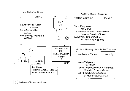
invention. For the purposes of particularity, Figure 6 is
provided to show the sequence of events in the delivery and
display of location identification information concerning the
called party using the Feature Support trigger and the
Analyze_Route response.
1. CPE 11 goes off-hook and end user (calling party)
dials directory number (DN) of called party.
2. SSP 10 does not encounter any other trigger before
the Feature Support trigger.
3. During the Info_Analyzed Trigger Detection Point, the
Feature Support Trigger is detected for the
DNNameDisplay (in this case CalledPartyNameDisplay)
and DNLocationIdDisplay (in this case
CalledPartyLocationIdDisplay).
4. An Info_Analyzed query (Event I) is transmitted to
SCP 24. Among other parameters, the query contains:
CalledPartyID = 613-225-6789
ActiveFeatureList = 0 0 0 0 0 0
CA 02256061 1998-12-11
b7 b6 b5 b4 b3 b2 bl bO
FeatureRequiredDataList = O O O O O
b7 b6 b5 b4 b3 b2 bl bO
5. SCP 24 retrieves from an internal database the
CalledParty name and LocationId and encodes them in
the DisplayText parameter which is transmitted to SSP
10 in the Analyze_Route response (Event II)
6. SSP 10 receives the CalledPartyName and LocationID
data, retrieves them from the Analyze_Route response
and transfers them into an interface message that is
transmitted to the telephone unit of the end user
(see Event III).
7. CPE 11 retrieves the data sent in the interface
message and displays the data on the telephone unit
display.
8. The end user may hang up to terminate the call, or
continue with call establishment.
The above example sets out the method to be followed
when location identification information concerning the called
party is delivered to the calling party only. A similar
method, with appropriate modifications, is followed in the
circumstance when location identification information
concerning the calling party is delivered to the called party.
Figure 7 shows the sequence of events in one embodiment of the
delivery and display of location identification information
concerning the calling party using the Termination Attempt
trigger and the AuthorizeTermination response. However,
persons skilled in the art will appreciate that there are many
AIN triggers that may be used adapted for use in accordance
with the present invention to deliver location identification
information to a called party concerning a calling party.
1. CPE 11 goes off-hook and end user (calling party)
CA 022~6061 1998-12-11
dials directory number (DN) of called party.
2. The call is routed to a terminating SSP 12.
3. At the terminating SSP 12 during the
Termination_Attempt Detection Point, the Termination
Attempt Trigger is detected. (Event 1)
4. A Termination_Attempt query (Event 2) is transmitted
to SCP 24. Among other parameters, the query
contains CallingPartyID parameter, and GenericName
parameter.
5. SCP 24 retrieves from an internal database the
CallingPartyName, CallingPartyLocationIdAddress, and
CallingPartyLocationIdStreetAddress and encodes them
in the DisplayText parameter which is transmitted to
SSP 12 in the Authorize_Termination response (Event
3)
6. SSP 12 receives the CalledPartyName and LocationID
data, retrieves them from the Analyze_Termination
response and transfers them into an interface message
that is transmitted to the CPE 25 of the called party
(see Event 4).
7. CPE 25 retrieves the data sent in the interface
message and displays the data on the telephone unit
display.
The two methods described above (the first method for
delivering location identification information concerning a
called party to a calling party, and the second method for
delivering location identification information concerning a
calling party to a called party) are both operative in either
an LNP or a non-LNP capable network.
In a second embodiment of the present invention,
there is provided at least one database (see database 105 in
Figure 3) containing location identification information
CA 022~6061 1998-12-11
resident at the central office switch SSP to which the end
user's CPE is connected. The structure and contents of this
SSP resident database depends on whether (I) the calling party
and/or called party are connected directly to the SSP, (ii)
whether the network is LNP capable or not, and (iii) whether
the directory number identifies an international location or
not.
For calling parties and called parties who are
directly connected to an SSP, there is provided a database that
has the same structure as Table 1. Since it is not feasible to
reproduce that type of database on all SSPs in a network (ie.
containing location identification information concerning each
and every directory number), there is also provided a second
database for directory numbers in respect of end users that are
not connected to that SSP. The structure of the second
database depends on whether the network in LNP-capable or not.
An example structure of the second database for a non-LNP
capable network is illustrated in Table 2:
Table 2
20 Key Data Field name Description
Area Code DNLocationIdAreaAddress Country, City
("XXX") + and/or Municipality
Office names
Code
("YYY")
The key to the second database in a non-LNP capable
network is six digits in length, consisting of a three digit
area code ("XXX") and a three digit office code ("YYY"). Using
this information as a key, it is only possible to deliver
location identification information that only identifies
geographic location such as country, city and/or municipality.
For this reason, no privacy control information is required.
Additionally, this type of database will be used in an LNP-
24
CA 022~6061 1998-12-11
capable network for the numbers that are not ported.
In an LNP-capable network for the ported numbers, an
example structure for the local SSP database would be as
illustrated in Table 3:
Table 3
Key Data Field name Description
LRN (6 to DNLocationIdAreaAddress Country, City
and/or Municipality
digits) names
In an LNP-capable network, every switch i8 assigned a
unique six to ten-digit Location Routing Number (LRN) that is
used to identify it to the network for call routing purposes.
An SCP provides the LRN of a recipient exchange for each ported
DN, to an originating exchange, so that calls can be routed
correctly. LRNs are six to ten digits long. In an LNP-capable
network, more than one LRN can be associated with a particular
geographic area. This means that different LRNs can have the
same DNLocationIdAreaAddress.
For international calls, there is provided a third
form of database resident at an SSP. The structure of this
third type of database is as illustrated in Table 4:
Table 4
Keyl Key2 Data Field Description
name
25 Country City Code DNLocationId Country, City
Code AreaAddress and/or Municipality
names
The following is an illustration of one method that
can be followed when location identification information stored
in any of the above tables at an SSP is sent to/from a calling
party and a called party. Dealing first with an SSP directly
... . . ....... ..
CA 022~6061 1998-12-11
connected to a calling party (hereinafter referred to as the
"calling party SSP") and referring back to Figure 3, steps 100
and 102 proceed in the same manner as described when location
identification information was stored at an SCP. At step 104,
local database 105 is not searched for subscriptions to AIN
triggers. Instead, local database 105 is searched for location
identification information concerning the called party such as
DNLocationIdAreaAddress and DNLocationIdStreetAddress (if
available). If the called party were directly connected to the
calling party SSP, then the information stored in Table 1 would
be retrieved. Where the called party was not directly
connected to the calling party SSP, then only information
stored in Table 2 would be retrieved in the non LNP-capable
network. In the LNP-capable network the information stored in
Tables 2 or 3 (depending on whether the called party is ported
or not ported, respectively) will be retrieved. The location
identification information retrieved from local database 105
would then be delivered to the calling party and displayed on
the display device of the calling party's CPE.
In another variation, location information concerning
the calling party could be delivered to the called party and
vice versa. Referring back to Figure 3, steps 100 and 102
proceed in the same manner as described above. At step 104,
local database 105 is searched for location identification
information concerning the calling party such as
DNLocationIdAreaAddress and DNLocationIdStreetAddress (if
available). This information would then be added to an IAM
ISUP message delivered to the SSP connected to the called party
(hereinafter referred to as the "called party SSP"). An
enhanced IAM ISUP message can carry location identification
information in the existing DisplayText parameter, or in a new
parameter entitled DNLocationID. When the enhanced IAM ISUP
26
CA 022S6061 1998-12-11
message is received at the called party's SSP, location
identification information is transferred into the alerting
message sent to the called party's CPE. Concurrently, there is
a search of local database 105 resident at the called party's
SSP for the location identification information of the called
party. When found, the called party's location identification
information is added to an enhanced ISUP altering confirmation
message and sent back to the called party's SSP for delivery to
the called party's CPE. In order to signal to the called
party's SSP that the called party's location identification
information is required by the calling party's SSP, the
parameter FeatureRequiredDataList (as described above) should
be used in the IAM ISUP message sent to the called party's SSP.
Persons skilled in the art will appreciate that there
are a variety of ways location identification information
stored at an SSP could be delivered to a calling party and/or a
called party, and that the above method is only an illustration
of this embodiment of the invention. Other means of storing
and delivering location identification information are
contemplated, including an implementation whereby location
identification information is stored by each calling party's
CPE. When a call is initiated, the calling party's location
identification information would be delivered from the calling
party's CPE, to the calling party's SSP, to the called party's
SSP, and to the called party's CPE. Concurrently, location
identification information concerning the called party would be
retrieved by the called party's SSP, and delivered to the
calling party's SSP and calling party's CPE.
The above description of a preferred embodiment
should not be interpreted in any limiting manner since
variations and refinements can be made without departing from
the spirit of the invention. The scope of the invention is
CA 02256061 1998-12-11
defined by the appended claims and their equivalents.
28