Note: Descriptions are shown in the official language in which they were submitted.
CA 02256406 1998-11-27
. . .. . .. .... .. ..
.. .. . . . . . . . . . ,
. . . . . ... . . ..
. .... . . . . . ... . ,
. . . . . . .
.. . .. ... .. ..
- 1 -
D~SCRIPTION
«AXIAL MOVEMENT LINEAR GAUGING HEAD»
Technical Field
The inventi-:~_ =ehtes to a 1 _r,.ear gauging ne ~~:~mprisirg
Si:p~Grt a:l~: ~-i~tCtiOn ~Tleai:~; ',niltii a Ca3liy ,i~~yii.~iyC a
longitudinal geometrical axis, an elongate, substantially
cylindrical-shaped element, axially movable with respect to
the support and protection means, a feeler element coupled
to an end of the elongate element, a_ position transducer,
including mutually displaceable parts connected to the
casing and to the elongate element, respectively, thrust
means located between the support and protection means and
the feeler element, and guide means, for guiding axial
displacements of the elongate element with respect to the
casing, with at least an axial bearing including a
plurality of rolling elements cooperating with the elongate
element.
Backcrround Art
Axial movement linear gauges, or gauging heads, that have
similar characteristics are from time conventional in the
art. Two embodiments are disclosed in U.S. patent US-A-
4347492. A first head, illustrated as prior art in figure 1
of the U.S. patent, has the typical structure of the
aforementioned, so-called "cartridge" heads, including a
cylindrical spindle, axially sliding within a casing by
means of a guide device consisting of an antifriction
bearing and carrying at one end a feeler for touching the
workpiece to be checked and at the other end a
ferromagnetic core, that translates inside associated
windings, as a consequence of axial displacements of the
spindle.
,MENDED S~tFtT .
CA 02256406 1998-11-27
.. . .. .... .. ..
.. .. . . . . . . . . . .
. . . . . ... . . ..
' . . . . .... . . . . . ... .
. . ,
. . .. . .. ... .. ..
- 2 -
TrLe antifriction bearina comprises balls and a cane with
holes for seating the balls, that contact both r_he external
surface of the spindle and t:he internal surface of the
casing. The sliding of the cylindrical spindle is enabled
by the rolling of the balls on the two surfaces with which
it contacts. Consequently, slidings of the spindle cause
slidings of _.'.e whole cage .
_ . ..
Tne 5tructu~~~ of t:~e cartr~eg' .reads u~sclosea -i~ she J. ~ .
patent are subject to some drawbacks attributable to the
great delicacy and care required for the assembly of the
guide device.
In fact, for the purposes of a correct performance, the
employed antifriction bearings have the need to undergo
delicate assembly operations, owing to the fact that, among
casing, balls and spindle, there need to be a coupling with
a theoretically null clearance, with a very tight
tolerance. Furthermore, it is necessary that the various
component parts be in well defined reciprocal longitudinal
positions, for the sake of preventing inappropriate
limitations to the displacing of the cage of the bearing
in
the course of the slidings between spindle and casing. This
means that the component parts have to be manufactured so
that one part takes account of the other and assembled with
great care, hence implying additional expenses.
The "cartridge" heads with guide devices of this type are
subject to further drawbacks, arising from undesired
displacements of the cage seating the balls with respect
to
the previously mentioned accurate longitudinal position.
These displacements could be due, for example, to
vibrations of the head and the unavoidable clearances that
in practice exist. These displacements -more frequently
occurring in those applications where the measuring head
has a vertically arranged measurement axis- can improperly
limit the possibility of the bearing displacing and alter
the possible reciprocal displacements between spindle and
casing and, as a consequence, vary the measuring range,
till jamming the spindle.
AMENDED SHEET
CA 02256406 1998-11-27
.. . .. .... .. ..
.. .. . . . . . . . . .
. . . . . ... . . ..
. .... . . . . . ... .
. .
.. . .. ... .. ..
- 3 -
Antifriction bearings includincx balls are used in a number
. of devices comprising mutually movable elements, such as
probe for coordinate measuring machines that is shown
in international patent application v~10-A-8301301. The probe
has a stylus carrying a tip and angularly movable in any
radial direction. movements of the tip are mechanically
,..._..:~mitted to a:= ~u;.~err~al switch ,__~-ough a ball ~=~~_. gone
'.:aullilg and a 5__._~., Liii= ~citi.=.. ..__~i:Slat~.iig w~L:i __~~,.eCL
to the probe housing by means of an antifriction bearing
with balls.
British patent application GB-A-2107410 discloses a
recirculating ball-spline assembly t9 be incorporated in
industrial machines such as machine tools and industrial
robots and including a sleeve, a pair of cage halves, eight
sets of balls and a spline shaft having a square cross-
section.
Disclosure of the Invention
Object of the present invention is to provide a cartridge
head that has a particularly simple structure and
guarantees high standards of accuracy, repeatability,
reliability and a reduction of costs and time required for
the assembly of the various parts with respect to the known
structures.
This is achieved by a gauging head wherein the formerly
mentioned axial bearing further includes a hollow support
element, fixed with respect to the casing, and a guide
structure housed in the hollow support element, the hollow
support element and the guide structure defining internal
rolling surfaces, said rolling elements being housed inside
the support element and adapted to cooperate with the
internal rolling surfaces for recirculating in said hollow
support element.
Brief Description of the Drawings
APPENDED SHEET '
CA 02256406 1998-11-27
.. . .. .... .. ..
.. .. . . . . . . . . .
. . . . . ... . . ..
. .... . . . . . ... .
. . . . . . . . . .
.. . .. ... .. ..
- 3a -
A preferred embodiment of the :Linear gauging head according
to the invention is
no~,v described in
more detail ~:vi th
reference to the enclosed sheets of drawings, given by war
of non limit ing example, wherein:
Figure 1 is a longitudinal cross-sectional view of a
gauging head according to an embodiment of the invention;
~.~'~re 2 is an e:=-_rg._ci scale cr:~_ _._~: ti;~ra 1
vi ew _ _
1y
~:~e ~u.~~-~~ig Dead si~e,v:: ~._ figure 1, u~~'__ a-cn J lire
_-
in figure 1; and
Figure 3 is a longitudinal cross-sectional view of a
-
detail of the gauging
head shown in figure
1, taken along
line III-III in figure 2.
Best Mode for Carrying Out the Invention
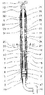
The axial movement gauging head shown in figure 1 comprises
support and protection means with a tubular, substantially
cylindrical-shaped, steel casing 1 that defines a
longitudinal geometrical axis, a substantially cylindrical
internal surface 2 with a limiting annular projection 2'
and a threaded end portion 6, and a rear closure element 3
coupled (more specifically, glued) to casing 1. A spool 4
a~,'='yi)i:~ Si'~~
CA 02256406 1998-11-27
WO 97/46849 PCT/EP97/02865
- 4 -
is housed in casing 1 and defines a longitudinal opening 5
and three external annular seats 7, 8 and 9.
An elongate element, or spindle, 10 is inserted in and
movable with respect to casing 1 and a feeler element with
a spherical feeler I2, for contacting a workpiece to be
checked 48, is coupled (for example, screwed) to an end of
spindle 10 that protrudes from the tubular casing 1.
An inductive differential position transducer comprises a
primary winding 13, two secondary windings 14 and 15 and a
core 16 made of ferromagnetic material. The windings 13, 14
and 15 are tightly wound -according to a known technique-
about spool 4 at the annular seats 7, 8 and 9,
respectively, whereas core 16 is fixed (for example, glued)
to a stem 17 that is coupled to spindle 10 at the opposite
end with respect to the one carrying the feeler element 12.
Spool 4 with associated windings 13 , 14 and 15 is coupled
to tubular casing 1, i.e. the external surface of windings
13, 14 and 15 is glued to the internal surface 2 of tubular
casing 1.
Guide means, for guiding axial displacements of spindle 10
with respect to casing 1, comprise two axial bearings, with
recirculating rolling elements, for example recirculating
ball bushings, 18 and 19, per se known, housed in casing 1
at longitudinally reciprocally spaced out positions. In the
bearings 18 and 19, the rolling elements, in particular
balls 29, roll on inside surfaces and contact the external
surface of spindle 10, as will be better explained
hereinafter. As also shown in figure 2, each of the
recirculating ball bushings 18 and 19 has a hollow support
element 20 (and 20') with a substantially cylindrical
shape, that defines an internal surface 49 and houses a
guide structure 50 made, for example, of synthetic resin
polimers, such as "Teflon" (registered trade mark), and
fixed to the hollow support element 20 in contact with the
aforesaid surface 49. The guide structure 50 defines a
substantially cylindrical longitudinal through hole 21 for
the partial insertion of spindle 10. Through hole 21
CA 02256406 1998-11-27
WO 97/46849 PCT/EP97/02865
- 5 - -
defines a cylindrical surface 22 of the guide structure 50
that has longitudinal slits 28. The guide structure 50 has
moulded portions 11, that, together with portions of the
surface 49, define internal rolling surfaces 23 that limit
internal circulation tracks 24 where balls 29 are seated.
Each track 24 has a first longitudinal portion 25,
connected with one of the slits 28, a second longitudinal
portion 26, substantially reciprocally parallel, and curved
connecting portions 27 between these longitudinal portions
25 and 26. The arrangement of the moulded portions 11 is
such that the longitudinal portions 25 and 26 of each track
24 are adjacent to each other and to the cylindrical
surface 22. The slits 28, have specific dimensions so as to
withhold the balls 29 within the associated rolling track
24 and enable the balls 29 to partially protrude with
respect to the cylindrical surface 22 and touch the
external surface of spindle 10 when they are in the
associated first longitudinal portion 25.
Elements for the longitudinal positioning and clamping
comprise a first, tubular-shaped spacer element 30 and a
second, tubular-shaped spacer element 31 housed in casing 1
and arranged, respectively, between the annular projection
2~ and the support element 20 of bearing 18, and between
the support elements 20 and 20~ of the two bearings 18 and
19 and a threaded clamping ring nut 32, also tubular-
shaped, coupled to the threaded end portion 6 of casing 1
with an end abutting on a base surface of the hollow
element 20~ of bearing 19.
A pin 33 is radially coupled to spindle 10 and carries at
its free end an idle small wheel 34. A slit 35,
longitudinally formed in the second spacer element 31,
houses -with limited angular clearance- the small wheel 34
that slides therein in the course of the longitudinal
displacement of spindle 10 with respect to casing l, hence
limiting the rotation of spindle 10 about its axis.
Thrust means comprise an abutment ring 37, coupled to and
coaxial with spindle 10, and a compression helical spring
CA 02256406 1998-11-27
WO 97/46849 PCT/EP97/02865
- 6 - '
36 arranged between a base surface of the support element
20' of bearing 19 and the abutment ring 37.
An additional abutment ring 38, coupled to spindle 10, is
in abutment on a base surface of an adjustment ring nut 39,
internally coupled to the clamping ring nut 32 by means of
a threaded coupling, for defining and adjusting the
longitudinal position of spindle 10, biased by spring 36,
when feeler 12 does not contact the workpiece 48.
An abutment surface 41, integral with spool 4, and an
abutment surface 40 of spindle 10 cooperate for defining
the stroke limit of spindle 10, when feeler 12 contacts
workpiece 48, offering resistance to the bias of spring 36.
A flexible, tubular-shaped sealing gasket 44 has one of its
ends coupled to the area where feeler 12 and spindle 10 are
connected, and the other end coupled to the end portion 6
of tubular casing 1.
The rear, closure element 3 has a through hole 45 for the
electric connection of the windings 13, 14 and 15 of the
differential transducer with external power supply, display
and processing devices (schematically shown and identified
by reference number 46 in figure 1) , by means of the wires
of a cable 47.
The assembly of the various component parts of the
described and illustrated gauging head is performed in a
particularly simple and rapid way. More specifically, once
spool 4 -that carries the windings 13, 14 and 15- has been
coupled to casing 1 by gluing the windings as already
described, some component parts, namely abutment ring 38,
bushing 19, pin 33, ring 37, the second spacer element 31
and spring 36, are coupled to spindle 10. Then, the first
spacer element 30, bushing 18 and spindle 10 -carrying the
formerly mentioned component parts- are inserted in
sequence in casing 1 and the whole is locked by ring nut
32. The position of the recirculating ball bushings 18 and
19, in particular the longitudinal positions of the
associated support elements 20 and 20' in casing 1 are so
CA 02256406 1998-11-27
WO 97/46849 PCT/EP97/02865
defined and fixed by means of the thrust of clamping ring
nut 32 and the presence of the spacer elements 30 and 31.
When the gauging head is in normal operating conditions and
there is no contact occurring between feeler 12 and
workpiece 48, as illustrated in figure 1, spring 36 urges
spindle 10 to reach a rest position defined by the
cooperation of the abutment ring 38 with the adjustment
ring nut 39. Subsequently, when contact occurs (in any
whatever manual or automatic known way, herein neither
illustrated nor described) between feeler 12 and a surface
of workpiece 48, spindle 10 displaces, with respect to
casing 1 and in opposition to the action of spring 36,
guided by the recirculating ball bushings 18 and 19, along
a rectilinear path parallel to the longitudinal axis of
casing 1.
More specifically, balls 29 touch the external surface of
spindle 10 through slits 28 and roll at one side on it and
at the other on corresponding internal surfaces 23, due to
the thrust that spindle 10 undergoes, so circulating along
tracks 24.
The displacement of spindle 10 causes core 16 to displace
within windings 13, 14 and I5 and a corresponding output
voltage variation at the terminals of the secondary
windings 14 and 15, according to the known functioning
principle of an inductive differential transducer. By means
of the electric connection comprising the wires of cable
47, the voltage variation with respect to a zero condition
(defined in a known way in a previous zero setting phase of
the head), is detected in the external devices 46 and a
signal relating to the amount of displacement from the rest
position is displayed.
The use of recirculating ball bushings 18 and 19 in the
herein described and illustrated linear gauge provides
specific characteristics insofar as simplicity, reliability
and economic convenience are concerned. The use of
recirculating ball bushings 18 and 19 enables, among other
things, to assemble various component parts in an extremely
CA 02256406 1998-11-27
WO 97!46849 PCT/EP97/02865
_ g _
simple way, as previously briefly described. This is due to
the fact that, in contrast with what occurs in the known
devices employing bearings that have to displace too with
respect to the spindle and the casing for enabling
reciprocal displacements between spindle and casing, it is
not necessary to couple the various parts (casing, spindle,
guide with balls) and define their reciprocal position with
an extremely high degree of accuracy and a theoretically
null clearance. A limited radial clearance between bushings
18, 19 and spindle 10 does not give rise to problems
relating to undesired displacements, since the bushings 18
and 19 are held in the correct position by the spacer
elements 30, 31 and the clamping ring nut 32. On the other
hand, a limited clearance (for example, in the order of one
or two Vim) can easily be achieved and does not affect the
accuracy and repeatability characteristics of the head.
According to other possible variants, there can be foreseen
a gauge that differs insofar as the material and/or shape
and/or number of components are concerned with respect to
what has been herein so far illustrated and described.
There can be utilized just one recirculating ball bushing,
with a greater longitudinal extension with respect to that
of the disclosed bushings 18 and 19, or, on the contrary,
there can be provided more than two bushings.
Moreover, the reciprocal arrangement of the bushings 18 and
19 and spool 4 that carries the windings 13, 14 and 15 and
the coupling of core 16 to spindle 10 can differ (for
example, bushings 18 and 19 can be arranged at the sides of
spool 4 ) .
Furthermore, the axial bearings can comprise rolling
elements other than balls 29, as, for example, cylindric
rollers or rollers of another known shape.