Language selection

Search

Patent 2256810 Summary

Third-party information liability

Some of the information on this Web page has been provided by external sources. The Government of Canada is not responsible for the accuracy, reliability or currency of the information supplied by external sources. Users wishing to rely upon this information should consult directly with the source of the information. Content provided by external sources is not subject to official languages, privacy and accessibility requirements.

Claims and Abstract availability

Any discrepancies in the text and image of the Claims and Abstract are due to differing posting times. Text of the Claims and Abstract are posted:

  • At the time the application is open to public inspection;
  • At the time of issue of the patent (grant).
(12) Patent: (11) CA 2256810
(54) English Title: WORKLIGHT WITH STAND
(54) French Title: LAMPE DE TRAVAIL AVEC SUPPORT
Status: Expired and beyond the Period of Reversal
Bibliographic Data
(51) International Patent Classification (IPC):
  • F21V 21/10 (2006.01)
  • F16M 11/20 (2006.01)
  • F21V 21/06 (2006.01)
  • F21V 21/12 (2006.01)
  • F21V 21/22 (2006.01)
(72) Inventors :
  • QIAN, PEI SHENG (China)
(73) Owners :
  • REGENT LIGHTING CORPORATION
(71) Applicants :
  • REGENT LIGHTING CORPORATION (United States of America)
(74) Agent: FINLAYSON & SINGLEHURST
(74) Associate agent:
(45) Issued: 2003-12-09
(22) Filed Date: 1998-12-22
(41) Open to Public Inspection: 1999-07-22
Examination requested: 1999-02-11
Availability of licence: N/A
Dedicated to the Public: N/A
(25) Language of filing: English

Patent Cooperation Treaty (PCT): No

(30) Application Priority Data:
Application No. Country/Territory Date
09/056,334 (United States of America) 1998-04-07
60/072,163 (United States of America) 1998-01-22

Abstracts

English Abstract


The invention is a worklight and stand having a multi-legged support and a main pole
consisting of three segments. The leg support increases the stand's overall resistance to tipping as
well as increases the stand's load resistance. The worklight is adjustable, allowing for the aiming
of light in multiple directions. The ability to break the main pole into three segments allows for the
storage or packaging of the stand within a container of smaller dimension than necessary for a stand
of only two segments.


Claims

Note: Claims are shown in the official language in which they were submitted.

The embodiments of the invention in which an exclusive property or privilege
is claimed are
defined as follows:
1. A worklight positionable on a support surface comprising:
a stand and at least one light mounted on said stand;
said stand comprising of at least three releasably engageable segments which
join together to form a main pole having a first end section and an opposingly
located second
end section;
said at least one light being mounted to said first end section and a support
base
being attached to said second end section; and
said support base comprising at least five equally spaced legs which extend
downwardly from said main pole to support said worklight on said support
surface.
2. The worklight of claim 1 wherein said support base further comprises:
a first collar, slidably mounted upon said main pole, said legs being
connected
to said slidably mounted collar; and
a second collar fixably mounted on said main pole below said first collar
having
moveable rods connected between each of said legs and said fixed second collar
by fasteners,
said rods allowing said legs to remain connected to said fixed second collar
when said sliding
first collar is in motion.
3. The worklight of claim 1 wherein said at least one light is mounted upon a
crossbar perpendicular to said main pole by an adjustable bracket.
4. The worklight of claim 1 wherein said at least one light is mounted
directly
upon said main pole of said stand, by an adjustable bracket.
-6-

5. The worklight of claim 3 wherein the cross bar is mounted perpendicularly
onto
said main pole of said stand by a screw knob located at the midpoint of said
cross bar.
6. The worklight of claim 3 or 4 wherein said adjustable bracket facilitates
the
aiming of light from said at least one worklight in a selected direction.
7. The worklight of claim 3 or 4 wherein said at least one light comprises:
a halogen bulb;
said halogen bulb being surrounded by a heat resistive protective casing;
a tempered glass lens mounted within said casing;
safety wire guards mounted over said glass lens;
a power cord; and
a handle associated with said casing.
8. The worklight of claim 7 wherein said handle mounted upon said at least one
light assists in aiming light from said at least one light in a selected
direction.
9. The worklight of any one of claims 1 - 8 wherein there are two lights.
10. The worklight of any one of claims 1 - 9 which, when in a disassembled
state,
may be stored or packaged within a container of smaller dimension than a
container to store
a stand with a two segmented main pole.
-7-

Description

Note: Descriptions are shown in the official language in which they were submitted.


CA 02256810 2002-10-17
WORKLIGHT WITH STAND
Background of the Invention
The present invention relates to a portable worklight including a stand. More
particularly, the worklight of the present invention consists of a mufti-
legged support structure
which serves to increase both the load resistance and tipping resistance of
the stand. At least
one light is mounted upon an adjustable bracket, allowing light to be directed
in multiple
directions. As well, the vertical pole of the stand is separable into three
segments. This
segmented pole allows the stand to be packaged and stored in a container of
smaller
dimension than a two-segmented stand. This serves to allow 1°or a more
efficient use of space
in shipping and in the retail setting.
Summary of the Invention
The invention provides a worklight positiunable on a support surface
comprising a
stand and at least one light mounted an the stand, the stand is comprised of
at least three
releasably engageable segments which join tragether to form a main pole having
a first end
section and an opposingly located second end section. 1'he light is mounted to
the first end
section and a support base is attached to the second end section. The support
base is
comprised of at least five equally spaced legs which e~ctend clownwardly from
the main pole
to support the worklight on the support surf ace.

CA 02256810 2002-10-17
The present invention further improves the structure required to support: a
worklight.
It increases resistance to tipping by 63% as well as increases the structure's
load bearing
ability by 23%. Further, it allows for the structure to be stored or packaged
within a
substantially smaller space when in a disassembled state.
More particularly the worklight of the present irmention uses a mufti-legged
support
consisting of at least five legs which increases both the tipping resistance
and the; load bearing
capabilities of the stand. Preferably two Halogen lights are mounted upon a
crossbar which
connects perpendicularly to the main pole. Brackets connecting the lights to
the crossbar are
adjustable, allowing light to be aimed in multiple directions. Since the main
pole breaks
down to three segments, the dimension of the container in which the stand may
be stored or
packaged is smaller than that required for a stand with a main pole of two
segments.
Brief Description of the Drawings
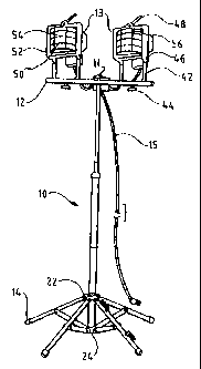
FIGURE 1 is perspective view of the worklight with stand fully assembled and
with
the stand's legs in an extended position.
FIGURE 2 is perspective view of the stand showing the segments of the vertical
pole
and with the stand's legs partially contracted.
FIGURE 3 is a cut-away view of a container for storing or packaging the
worklight
with stand.
_.

CA 02256810 2002-10-17
FIGURE 4 is an end cut-away view of the container for storing or packaging the
stand
showing the stand disassembled and placed within the Container.
FIGURE 5 is a cut-away view from a bottom perspective of the container for
storing
or packaging the stand showing the stand disassembled and placed within the
container.
FIGURE 6 is a cut-away view from a top perspectivEof the container for storing
or
packaging the stand showing the stand disassembled and placed within the
container.
Description of the Preferred Embodiment
Figure 1 shows the worklight with stand in its fully assembled state. Figure 2
shows
the worklight with stand in a disassemblLd state. The pr~:ferred embodiment
contains a
vertical main pole 10 formed of either mztal or plastic. Main pole 10 is
connected at its
upper end to a cross bar 12 by screw-knob 11 and at its lower end to a mufti-
legged support
14. Two lights 13 are mounted onto cross bar 12 and power cord 15 connects to
each light
13. Main pole 10 consists of upper segment 16, middle segment 18 and lower
segment 20.
Two upper collars 22 and lower collar 24 are rrrounted onto lower segment 20.
A gripping
handle 26 in the form of a peripheral ridge is mounted onto middle segment 18
which enables
the worklight to be moved when assembled.
In the preferred embodiment, support 14 consists of five legs 28. Each leg 28
is of
equal length and connected at one end to collar 22, while the other end is
covered by
-3-

CA 02256810 2002-10-17
protective cap 30. One end each of five rods 32 are secured to the mid-point
of legs 28 by
fasteners 34. The opposing end of each rod 32 is secured to collar 24.
Fasteners 34 do not
rigidly lock each rod 32 into place, but allow for the movement of rods 32,
legs 28 and collar
2 2 in combination.
In the preferred embodiment, each light 13 is connected to cross bar 12 by an
adjustable bracket 42. Bracket 42 mounts onto cross bar 12 by adjustable screw
44. Bracket
4;? connects with each light 13 by adjustable screw 46. 1-landle 48 is located
on top of each
light 13 and in conjunction with adjustable screw 46 allows the aiming of the
light in multiple
directions. Light 13 comprises a bulb 50 surrounded by a heat resistive
protective casing 52.
A tempered glass lens 54 with safety wire guards 56 is mounted within casing
52.
In use, the five legs 28 of the preferred embodiment of support 14 of the
worklight
with stand increases the stand's resistance to tipping by 63%. The use of five
legs 28 also
increases the worklight with stand's load bearing capability by 25%.
In the preferred embodiment, the disassembled stand fits within container 40,
a
container with dimensions smaller than those for a corresponding container to
store a stand
comprising a two segmented main pole. Deducing the sire c>f the container is
accomplished
by first using three segments 16, 18 and 20 to form main pole 10. It
has been found that as the number of segments is increased, the length of the
container used to store the light i~ decreased as well. Reducing the length
_4_

CA 02256810 1998-12-22
Attorney
Docket No. 2490
of the container is important since it reduces the space needed to store the
light for the end-user and
it also reduces the retail space needed to display the product in a retail
setting.
As shown in Figures 3 - 6, the device is stored in a compact container 100 by
placing the
lights in one section of the box and dividing the lights from the poles 104
from the lights by a
diagonally directed divider 102. Arranging the product in this manner greatly
reduces the size of the
container needed to house the product.
While the main pole 10 and mounted collars 22 and 24 are generally rounded in
shape, it
should be noted that pole 10 and collars 22 and 24 could also be formed
rectangular or square in
shape. It should be understood that various changes and modifications to the
preferred embodiment
described would be apparent to those skilled in the art. Changes and
modifications can be made
without departing from the spirit and scope of the present invention and
without diminishing its
intended advantages. It is, therefore, intended that such changes and
modifications be covered by
the following claims.
-5-

Representative Drawing
A single figure which represents the drawing illustrating the invention.
Administrative Status

2024-08-01:As part of the Next Generation Patents (NGP) transition, the Canadian Patents Database (CPD) now contains a more detailed Event History, which replicates the Event Log of our new back-office solution.

Please note that "Inactive:" events refers to events no longer in use in our new back-office solution.

For a clearer understanding of the status of the application/patent presented on this page, the site Disclaimer , as well as the definitions for Patent , Event History , Maintenance Fee  and Payment History  should be consulted.

Event History

Description Date
Time Limit for Reversal Expired 2006-12-22
Inactive: IPC from MCD 2006-03-12
Letter Sent 2005-12-22
Grant by Issuance 2003-12-09
Inactive: Cover page published 2003-12-08
Inactive: Final fee received 2003-09-18
Pre-grant 2003-09-18
Notice of Allowance is Issued 2003-03-24
Letter Sent 2003-03-24
Notice of Allowance is Issued 2003-03-24
Inactive: Approved for allowance (AFA) 2003-03-06
Amendment Received - Voluntary Amendment 2002-10-17
Inactive: S.30(2) Rules - Examiner requisition 2002-04-22
Amendment Received - Voluntary Amendment 2002-02-07
Inactive: S.30(2) Rules - Examiner requisition 2002-01-03
Inactive: Cover page published 1999-07-27
Application Published (Open to Public Inspection) 1999-07-22
Letter Sent 1999-03-09
Request for Examination Received 1999-02-11
Inactive: First IPC assigned 1999-02-11
Inactive: IPC assigned 1999-02-11
Classification Modified 1999-02-11
Inactive: IPC assigned 1999-02-11
Request for Examination Requirements Determined Compliant 1999-02-11
All Requirements for Examination Determined Compliant 1999-02-11
Inactive: Filing certificate - No RFE (English) 1999-01-26
Filing Requirements Determined Compliant 1999-01-26
Application Received - Regular National 1999-01-26

Abandonment History

There is no abandonment history.

Maintenance Fee

The last payment was received on 2003-09-29

Note : If the full payment has not been received on or before the date indicated, a further fee may be required which may be one of the following

  • the reinstatement fee;
  • the late payment fee; or
  • additional fee to reverse deemed expiry.

Please refer to the CIPO Patent Fees web page to see all current fee amounts.

Fee History

Fee Type Anniversary Year Due Date Paid Date
Registration of a document 1998-12-22
Application fee - standard 1998-12-22
Request for examination - standard 1999-02-11
MF (application, 2nd anniv.) - standard 02 2000-12-22 2000-12-04
MF (application, 3rd anniv.) - standard 03 2001-12-24 2001-09-27
MF (application, 4th anniv.) - standard 04 2002-12-23 2002-09-24
Final fee - standard 2003-09-18
MF (application, 5th anniv.) - standard 05 2003-12-22 2003-09-29
MF (patent, 6th anniv.) - standard 2004-12-22 2004-11-04
Owners on Record

Note: Records showing the ownership history in alphabetical order.

Current Owners on Record
REGENT LIGHTING CORPORATION
Past Owners on Record
PEI SHENG QIAN
Past Owners that do not appear in the "Owners on Record" listing will appear in other documentation within the application.
Documents

To view selected files, please enter reCAPTCHA code :


To view images, click a link in the Document Description column. To download the documents, select one or more checkboxes in the first column and then click the "Download Selected in PDF format (Zip Archive)" or the "Download Selected as Single PDF" button.

List of published and non-published patent-specific documents on the CPD .

If you have any difficulty accessing content, you can call the Client Service Centre at 1-866-997-1936 or send them an e-mail at CIPO Client Service Centre.


Document
Description 
Date
(yyyy-mm-dd) 
Number of pages   Size of Image (KB) 
Representative drawing 1999-07-22 1 7
Representative drawing 2003-11-05 1 9
Cover Page 2003-11-05 1 35
Description 1998-12-22 4 152
Abstract 1998-12-22 1 15
Claims 1998-12-22 3 59
Description 2002-10-17 5 183
Drawings 2002-10-17 2 93
Claims 2002-10-17 2 70
Cover Page 1999-07-22 1 30
Drawings 2002-02-07 2 87
Description 2002-02-07 5 162
Claims 2002-02-07 2 56
Drawings 1998-12-22 2 70
Courtesy - Certificate of registration (related document(s)) 1999-01-26 1 115
Filing Certificate (English) 1999-01-26 1 163
Acknowledgement of Request for Examination 1999-03-09 1 178
Reminder of maintenance fee due 2000-08-23 1 110
Commissioner's Notice - Application Found Allowable 2003-03-24 1 160
Maintenance Fee Notice 2006-02-16 1 172
Correspondence 2003-09-18 1 31