Language selection

Search

Patent 2256916 Summary

Third-party information liability

Some of the information on this Web page has been provided by external sources. The Government of Canada is not responsible for the accuracy, reliability or currency of the information supplied by external sources. Users wishing to rely upon this information should consult directly with the source of the information. Content provided by external sources is not subject to official languages, privacy and accessibility requirements.

Claims and Abstract availability

Any discrepancies in the text and image of the Claims and Abstract are due to differing posting times. Text of the Claims and Abstract are posted:

  • At the time the application is open to public inspection;
  • At the time of issue of the patent (grant).
(12) Patent Application: (11) CA 2256916
(54) English Title: SPLATTER SCREEN
(54) French Title: ECRAN ANTI-PROJECTIONS
Status: Deemed Abandoned and Beyond the Period of Reinstatement - Pending Response to Notice of Disregarded Communication
Bibliographic Data
(51) International Patent Classification (IPC):
  • A47J 36/06 (2006.01)
  • A47J 37/10 (2006.01)
(72) Inventors :
  • KERR, HELEN (Canada)
(73) Owners :
  • BROWNE & CO. LTD./CIE LTEE
(71) Applicants :
  • BROWNE & CO. LTD./CIE LTEE (Canada)
(74) Agent: GOWLING WLG (CANADA) LLP
(74) Associate agent:
(45) Issued:
(22) Filed Date: 1998-12-22
(41) Open to Public Inspection: 2000-03-15
Examination requested: 2003-12-04
Availability of licence: N/A
Dedicated to the Public: N/A
(25) Language of filing: English

Patent Cooperation Treaty (PCT): No

(30) Application Priority Data:
Application No. Country/Territory Date
09/153,594 (United States of America) 1998-09-15

Abstracts

English Abstract


A cover or splatter screen for a cooking
vessel which in use rests atop the cooking vessel to
prevent splashing of hot liquid, especially fatty
liquid from the vessel during cooking, while
permitting passage of water vapor and steam from the
cooking vessel; the cover has a support frame and a
wire mesh screen extending between opposed sides of
the frame and a plurality of support legs in spaced
apart relationship extending outwardly of the support
frame and downwardly of the wire mesh screen; the
support legs support the cover in a free-standing
configuration on a flat supporting surface with the
wire mesh screen spaced from the flat supporting
surface; typically the flat supporting surface is a
kitchen working surface, and thus the cover may be
supported on the kitchen working surface with the wire
mesh screen in non-contacting relationship with the
kitchen working surface, whereby soiling of the
kitchen working surface by fats retained by the wire
mesh screen during working is avoided.


Claims

Note: Claims are shown in the official language in which they were submitted.

-8-
CLAIMS:
1. A cover adapted to rest loosely atop a
cooking vessel to prevent splashing of hot liquids
from the vessel, while allowing passage of vapors from
the vessel during cooking, comprising:
a cover member having an upper face and a
lower face and comprising a support frame and a
generally planar wire mesh screen extending between
opposed sides of said support frame,
said mesh screen being adapted to extend
across an opening of a cooking vessel to intercept hot
liquid splashing outwardly therefrom, while allowing
passage of vapor,
a plurality of support legs in spaced apart
relationship extending outwardly of said support frame
and downwardly of said lower face,
said support legs being adapted to support
said cover member, in a free-standing configuration,
or a flat supporting surface, with said lower face
spaced from the flat supporting surface.
2. A cover according to claim 1 further
including a handle member extending outwardly of said
support frame.
3. A cover according to claim 2, wherein said
handle is elongate, extending outwardly from said
frame and being disposed at an acute angle to said
common plane containing said leg support surfaces and
said handle support surface.
4. A cover according to claim 1, 2 or 3,
wherein said support legs have support surfaces
adapted to engage the flat supporting surface in said
free-standing configuration, said leg support surfaces

-9-
lying in a common plane spaced from said wire mesh
screen; and said handle member having an outer end
having a handle support surface, said handle support
surfaces lying in said common plane containing said
leg support surfaces.
5. A cover according to claim 1, 2, 3 or 4,
wherein said plurality of support legs comprises four
legs, said legs being disposed in symmetrical manner
about said cover member, in said spaced apart
relationship.
6. A cover according to claim 1, 2, 3, 4or 5,
wherein said support legs are arcuately curved to
permit restrained lateral movement of the cover member
relative to the opening of the cooking vessel.
7 . A cover according to claim 1 , 2 , 3 , 4 , 5 or
6, wherein said frame is substantially circular.
8. A splatter screen for resting loosely atop a
cooking vessel to prevent splashing of hot liquid fat
from the cooking vessel while allowing escape of water
vapor and steam from the working vessel during
cooking, comprising:
a screen member having an upper face and a
lower face, in opposed relationship, said member
having a circular support frame and a generally planar
wire mesh screen extending between opposed sides of
said support frame,
said mesh screen being adapted to extend
across an opening of a cooking vessel and having a
mesh size to intercept hot liquid fat splashing
outwardly therefrom, while allowing escape of water
vapor and steam,

-10-
a plurality of support legs in spaced apart
relationship extending outwardly of said support frame
and downwardly of said lower face,
said support legs having leg support
surfaces and said support legs being adapted to
support said screen member, in a free-standing
configuration, on a flat support surface, with said
leg support surfaces contacting said flat supporting
surface, and said lower face spaced from, and in
non-contacting relationship with the flat support surface,
and
an elongate handle member extending
outwardly from said frame, said handle member having
an outer handle support surface,
said handle support surface and said leg
support surfaces lying in a common plane,
said elongate handle member being disposed
at an acute angle to said common plane.

Description

Note: Descriptions are shown in the official language in which they were submitted.


CA 02256916 1998-12-22
BACKGROUND OF THE INVENTTON
i) Field of the Invention
This invention relates to a cover having a
s wire mesh screen, for a cooking vessel, and in
particular a splatter screen.
ii) Description of Prior Art
Splatter screens are known which comprise a
generally planar wire mesh screen housed in a frame.
~o The screen is placed over the opening of a cooking
vessel, during the cooking operation; the mesh
openings in the screen are dimensioned such as to
prevent passage of particles of hot liquid, such as
hot liquid fat sprayed upwardly when frying or cooking
15 food stuff containing water and fat, while permitting
passage of vapors such as water vapor and steam.
Such splatter screens are of a generally
planar configuration, and the mesh screen is of a
significant area. When the splatter screen is removed
zo from the cooking vessel either temporarily during the
cooking operation, or at the termination of the
cooking operation, it is typically placed on an
adjacent available working surface available to the
cook in the kitchen.
z5 The kitchen working surface which
temporarily supports the splatter screen during the
cooking operation, or at the termination of the
cooking operation and prior to washing, becomes soiled
with fatty oil or grease retained by the wire mesh
3o which engages the kitchen working surface. This is
undesirable in that it results in a soiled kitchen
working surface, thereby reducing the kitchen working
surface available and also in that it necessitates
cleaning of both the splatter screen and the working
35 surface .

CA 02256916 1998-12-22
- 3 -
SUMMARY OF THE INVENTION
This invention seeks to provide a cover or
splatter screen having a mesh screen and support legs
which will support the cover in a free-standing
s configuration on a flat supporting surface with the
mesh screen spaced from t:he flat supporting surface.
In accordance with the invention, there is
provided a cover adapted to rest loosely atop a
cooking vessel to prevent splashing of hot liquids
~o from the vessel, while allowing passage of vapors from
the vessel during cooking, comprising:
a cover member having an upper face and a
lower face and comprising a support frame and a
generally planar wire mesh screen extending between
opposed sides of said support frame,
said mesh screen being adapted to extend
across an opening of a cooking vessel to intercept hot
liquid splashing outwardly therefrom, while allowing
passage of vapor,
2o a plurality of support legs in spaced apart
relationship extending outwardly of said support frame
and downwardly of said lower face,
said support legs being adapted to support
said cover member, in a free-standing configuration,
25 on a flat supporting surface, with said lower face
spaced from the flat supporting surface.
DESCRIPTION OF PREFERRED EMBODIMENTS
In a preferred embodiment, the support frame
30 of the cover is substantially circular, and a handle
member extends outwardly of the support frame.
The support legs have leg support surfaces
adapted to engage a flat supporting surface such as a
kitchen working surface, in the free-standing
35 configuration, when the cover is not atop the cooking
vessel. These leg support surfaces lie in a common

CA 02256916 1998-12-22
- 4 -
place spaced from the wire mesh screen, so as to
securely locate the wire mesh screen and retained fat
residue, spaced apart from and in non-contacting
relationship with the kitchen working surface.
s Preferably the handle has an outer end having a handle
support surface, said handle support surface lying in
the common plane which contains the leg support
surfaces; in this way, the handle functions as an
additional leg and assists in supporting the cover in
~o the free-standing configuration. In this latter
embodiment, the handle is suitably elongate, extending
outwardly from the support frame and disposed at an
acute angle to the aforementioned common plane.
Suitably there may be four support legs
15 disposed in a symmetrical manner about the cover
member, in said spaced apart relationship.
The support legs are conveniently arcuately
curved to permit restrained lateral movement of the
cover member relative to the opening of the cooking
zo vessel on which the cover rests.
By "restrained lateral movement" is meant
that the legs do not firmly engage the side walls of
the cooking vessel such that no lateral movement of
the cover would be possible, but rather the legs are
z5 fashioned to stably locate or seat the cover atop the
cooking vessel, with freedom to move laterally. This
is particularly achieved by the arcuate curvation of
the support legs.
In known manner, the wire mesh screen should
3o have mesh openings dimensioned to intercept or prevent
passage of hot liquids, for example, liquid fat
splashing upwardly and outwardly of the interior of
the cooking vessel, while allowing passage of vapors,
for example, water vapor and steam.
35 The mesh openings also permit visual
inspection of the food-stuff cooking in the vessel,

CA 02256916 1998-12-22
_5_
and by allowing escape of steam and water vapor
prevent undesirable pressure build-up in the cooking
vessel.
BRIEF DESCRIPTION OF DRAWINGS
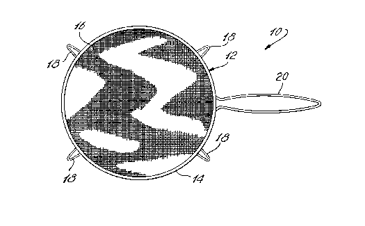
Fig. 1 is a plan view of a splatter screen
of the invention;
Fig. 2 is a side elevation of the splatter
screen of Fig. l;
~o Fig. 3 shows the splatter screen of Fig. 1
resting loosely on a cooking vessel, in use; and,
Fig. 4 is a side view of the splatter screen
of Fig. 1 in free standing configuration on a flat
working surface .
DESCRIPTION OF PREFERRED EMBODIMENTS WITH
REFERENCE TO THE DRAWINGS
With further reference to Figs. 1 and 2, a
splatter screen 10 comprises a cover member 12 having
zo a circular support frame 14 and a wire mesh screen 16
extending between opposed sides of frame 14.
Four support legs 18 extend outwardly of
circular support frame 14 and handle 20 extends
outwardly of circular support frame 14.
25 Splatter screen 10 has an upper face 22 and
a lower face 24 in opposed relationship with upper
face 22.
The support legs 18 extend downwardly of
lower face 24 and terminate at leg support surfaces
30 26. Similarly, handle 20 extends downwardly of lower
face 24 and terminates in a handle support surface 28.
The leg support surfaces 26 and the handle support
surface 28 all lie in a common plane 30, and handle 20
is inclined at an acute angle alpha to common plane
35 3 0 .

CA 02256916 1998-12-22
-6-
The support legs 18 as shown are
symmetrically disposed about frame 14 relative to
handle 20.
As more particularly shown in Fig. 4, the
s leg support surfaces 26 and handle support surface 28
function to support a splatter screen 10 in a free
standing configuration on a flat working surface such
as kitchen working surface 34.
Each of support legs 18 has an arcuate or
~o concavely curved inner face 27.
With further reference to Fig. 3, splatter
screen 10 is shown resting loosely on an open cooking
vessel 32. The curved inner faces 27 of support legs
18 permit restrained lateral movement of splatter
screen 10 on cooking vessel 32. By reference to Fig.
3, it can be seen that the support legs 18 do not
firmly engage the wall of the cooking vessel 32, but
the curved inner faces 27 while permitting lateral
movement also have a hooking action relative to the
20 open rim of the vessel 32 to provide stability of
location of the screen 1.0 on the vessel 32, and limit
or restrain the lateral movement of screen 10 relative
to vessel 32.
As can be more particularly seen in Fig . 4 ,
zs when splatter screen 10 is removed from its working
position on a cooking vessel 32, as shown in Fig. 3,
and is placed on a kitchen working surface 34, the
lower face 24 of the splatter screen 10 and more
especially the wire mesh screen 16, is supported by
3o the legs 18 and handle 20 in spaced apart relationship
with the kitchen working surface 34, so as to be in
non contacting relationship with such surface.
The splatter screen 10 can be fabricated
employing conventional metal working procedures. In
35 particular, the mesh screen 16 may be cut to shape and
folded at its peripheral edge about an elongate wire .

CA 02256916 1998-12-22
- 7 -
Support frame 14 may be formed from an elongate
cylindrical tube having a continuous narrow slot
adapted to receive the ware with the folded peripheral
edge of the screen 16. The screen mounted on the wire
s is inserted into the slot and the ends of the
cylindrical tube are secured together to form the
circular frame with the screen entrapped therein, the
tube then being subject clamping pressure to securely
clamp the wire with the peripheral edge of the screen
~0 16 therein. The legs 18 and handle 20 may be secured
to frame 14 as by welding. In the particular
embodiment shown, handle 20 has two arms each of which
may be welded to an opposed end of the cylindrical
tube which forms frame 1.4 thereby holding the ends of
15 the tube together with one end telescoped slightly
inside the other.
Variations of the specific and preferred
embodiment described hereinbefore will be evident to
persons in the art, and are considered to be within
zo the scope of the invention which is more especially
described by the claims hereinafter.

Representative Drawing
A single figure which represents the drawing illustrating the invention.
Administrative Status

2024-08-01:As part of the Next Generation Patents (NGP) transition, the Canadian Patents Database (CPD) now contains a more detailed Event History, which replicates the Event Log of our new back-office solution.

Please note that "Inactive:" events refers to events no longer in use in our new back-office solution.

For a clearer understanding of the status of the application/patent presented on this page, the site Disclaimer , as well as the definitions for Patent , Event History , Maintenance Fee  and Payment History  should be consulted.

Event History

Description Date
Application Not Reinstated by Deadline 2006-12-22
Time Limit for Reversal Expired 2006-12-22
Inactive: IPC from MCD 2006-03-12
Deemed Abandoned - Failure to Respond to Maintenance Fee Notice 2005-12-22
Inactive: Office letter 2005-09-09
Revocation of Agent Requirements Determined Compliant 2005-09-09
Appointment of Agent Requirements Determined Compliant 2005-09-09
Revocation of Agent Request 2005-09-07
Appointment of Agent Request 2005-09-07
Appointment of Agent Request 2005-08-08
Revocation of Agent Request 2005-08-08
Letter Sent 2003-12-23
All Requirements for Examination Determined Compliant 2003-12-04
Request for Examination Received 2003-12-04
Request for Examination Requirements Determined Compliant 2003-12-04
Inactive: Entity size changed 2002-11-19
Application Published (Open to Public Inspection) 2000-03-15
Inactive: Cover page published 2000-03-14
Inactive: Applicant deleted 1999-03-24
Inactive: Correspondence - Formalities 1999-02-22
Inactive: Single transfer 1999-02-22
Inactive: IPC assigned 1999-02-11
Classification Modified 1999-02-11
Inactive: First IPC assigned 1999-02-11
Inactive: Courtesy letter - Evidence 1999-02-02
Inactive: Filing certificate - No RFE (English) 1999-01-28
Filing Requirements Determined Compliant 1999-01-28
Application Received - Regular National 1999-01-27

Abandonment History

Abandonment Date Reason Reinstatement Date
2005-12-22

Maintenance Fee

The last payment was received on 2004-09-23

Note : If the full payment has not been received on or before the date indicated, a further fee may be required which may be one of the following

  • the reinstatement fee;
  • the late payment fee; or
  • additional fee to reverse deemed expiry.

Please refer to the CIPO Patent Fees web page to see all current fee amounts.

Fee History

Fee Type Anniversary Year Due Date Paid Date
Registration of a document 1998-12-22
Application fee - small 1998-12-22
MF (application, 2nd anniv.) - small 02 2000-12-22 2000-12-07
MF (application, 3rd anniv.) - small 03 2001-12-24 2001-11-01
MF (application, 4th anniv.) - standard 04 2002-12-23 2002-11-12
MF (application, 5th anniv.) - standard 05 2003-12-22 2003-10-27
Request for examination - standard 2003-12-04
MF (application, 6th anniv.) - standard 06 2004-12-22 2004-09-23
Owners on Record

Note: Records showing the ownership history in alphabetical order.

Current Owners on Record
BROWNE & CO. LTD./CIE LTEE
Past Owners on Record
HELEN KERR
Past Owners that do not appear in the "Owners on Record" listing will appear in other documentation within the application.
Documents

To view selected files, please enter reCAPTCHA code :


To view images, click a link in the Document Description column. To download the documents, select one or more checkboxes in the first column and then click the "Download Selected in PDF format (Zip Archive)" or the "Download Selected as Single PDF" button.

List of published and non-published patent-specific documents on the CPD .

If you have any difficulty accessing content, you can call the Client Service Centre at 1-866-997-1936 or send them an e-mail at CIPO Client Service Centre.


Document
Description 
Date
(yyyy-mm-dd) 
Number of pages   Size of Image (KB) 
Representative drawing 2000-02-28 1 23
Abstract 1998-12-22 1 29
Claims 1998-12-22 3 99
Description 1998-12-22 6 244
Drawings 1998-12-22 1 44
Cover Page 2000-02-28 1 54
Filing Certificate (English) 1999-01-28 1 163
Courtesy - Certificate of registration (related document(s)) 1999-03-24 1 117
Reminder of maintenance fee due 2000-08-23 1 110
Reminder - Request for Examination 2003-08-25 1 112
Acknowledgement of Request for Examination 2003-12-23 1 188
Courtesy - Abandonment Letter (Maintenance Fee) 2006-02-16 1 174
Correspondence 1999-02-02 1 27
Correspondence 1999-02-22 3 113
Correspondence 2005-08-08 3 70
Correspondence 2005-09-09 1 13
Correspondence 2005-09-09 1 16
Correspondence 2005-09-07 2 65