Language selection

Search

Patent 2257062 Summary

Third-party information liability

Some of the information on this Web page has been provided by external sources. The Government of Canada is not responsible for the accuracy, reliability or currency of the information supplied by external sources. Users wishing to rely upon this information should consult directly with the source of the information. Content provided by external sources is not subject to official languages, privacy and accessibility requirements.

Claims and Abstract availability

Any discrepancies in the text and image of the Claims and Abstract are due to differing posting times. Text of the Claims and Abstract are posted:

  • At the time the application is open to public inspection;
  • At the time of issue of the patent (grant).
(12) Patent: (11) CA 2257062
(54) English Title: THREADED NUT EXPANSION FASTENER
(54) French Title: PIECE DE FIXATION EXPANSIBLE A ECROU FILETE
Status: Term Expired - Post Grant Beyond Limit
Bibliographic Data
(51) International Patent Classification (IPC):
  • F16B 37/04 (2006.01)
  • F16B 37/02 (2006.01)
(72) Inventors :
  • DANBY, MICHAEL RICHARD (Canada)
  • MUMBY, JAMES RICHARD (Canada)
(73) Owners :
  • A. RAYMOND ET CIE
(71) Applicants :
  • EATON CORPORATION (United States of America)
(74) Agent: BORDEN LADNER GERVAIS LLP
(74) Associate agent:
(45) Issued: 2008-04-15
(22) Filed Date: 1998-12-30
(41) Open to Public Inspection: 1999-07-22
Examination requested: 2003-07-31
Availability of licence: N/A
Dedicated to the Public: N/A
(25) Language of filing: English

Patent Cooperation Treaty (PCT): No

(30) Application Priority Data:
Application No. Country/Territory Date
09/010,646 (United States of America) 1998-01-22

Abstracts

English Abstract

A barrel nut type fastener (100) is provided for securement within an opening (20) to a panel ("P") by a threaded member ("T") that when rotationally advanced through the barrel nut causes free-ends (14) and (14') of resilient legs (10) and (10') to move away from each other and respectively engage and urge resilient fingers (16) and (16') into contacting engagement with opposite sides of opening (20) with sufficient force to secure fastener (100) to panel, ("P").


French Abstract

Cet extrait concerne un écrou à portée cylindrique (100) qui doit être assujetti dans l'ouverture (20) d'un panneau (P) au moyen d'un élément fileté (T) qui, lorsqu'il est vissé dans l'écrou à portée cylindrique, écarte les extrémités libres (14 et 14') de jambes plastiques (10 et 10') l'une de l'autre et engrène respectivement des doigts plastiques (16 et 16') qui sont ainsi mis en contact avec les côtés opposés de l'ouverture (20) avec suffisamment de force pour attacher la pièce de fixation (100) au panneau (P).

Claims

Note: Claims are shown in the official language in which they were submitted.

CLAIMS
1. A fastener for securing an externally threaded member within an opening
through a panel, said
threaded member external threads having a prescribed outside diameter, and
said fastener comprising;
a base portion,
a hollow internally threaded nut portion extending away from one side of the
base portion, said nut
portion having a central longitudinal axis in general transverse relationship
to the base portion and having
internal threads operative to threadingly engage the threaded member threads
upon rotational advancement
of the threaded member therethrough,
a pair of resilient legs respectively extending from the opposite ends of the
base portion past the nut portion
and for a prescribed distance therebeyond and having corresponding windows
extending respectively
therethrough,
said legs thence curving inwardly towards each other and thence upwardly
towards the nut portion in
general parallel spaced-apart relationship to each other for a prescribed
distance with the nut portion central
longitudinal axis in substantial intermediate parallel relationship
therebetween with the distance between the
legs less than the outside diameter of the threaded member by a prescribed
amount,
said legs thence curving away from each other and through the windows
extending respectively
therethrough and ending in respective free-ends facing away from each other,
said legs having resilient fingers respectively extending from each leg
angularly outwardly away from each
other in a direction towards the base portion outwardly of the windows and
thence respectively curving
inwardly towards each other and ending in free-ends respectively located
between the base portion and
resilient leg free-ends, and
said fastener operative such that rotational advancement of the threaded
member through the nut
portion enables the threaded member to engage and urge the resilient legs away
from each other causing the
respective free-ends thereof to engage and urge the resilient fingers away
from each other and into contacting
engagement with opposite edges of the panel opening in a manner effective to
secure the fastener thereto.
2. The fastener of claim I wherein the threaded member is a machine screw and
the nut portion threads
are machine screw threads.
3. The fastener of claim 1 wherein the base portion and nut portion and
resilient legs and resilient fingers
are a one-piece sheet metal construction.

Description

Note: Descriptions are shown in the official language in which they were submitted.


CA 02257062 2006-12-29
THREADED NUT EXPANSION FASTENER
INTRODUCTION
The present invention relates generally to a fastener having a threaded nut
portion adapted to
threadingly secure an externally threaded member within a panel opening and
more particularly to such
fastener having a pair of resilient legs that are spread-apart by the threaded
member and which in turn urge
extremities of respective resilient fingers against opposite edges surrounding
the panel opening in a manner
effective to secure the fastener and the threaded member to the panel.
BACKGROUND OF THE INVENTION
Fasteners for securing threaded members within openings through panels have
been known for many years
of which examples are respectively disclosed in United States Patent Nos.
2,426,799; 2,707,013 and
4,595,325 of which all are owned by the Assignee of the present invention and
none of which operate in
the manner of the fastener of the present invention.
For example, the fastening device of United States Patent No. 2,426,799 is
secured to a panel "A" by a
squeezing force applied to its opposite faces by a threaded member "B" and in
United States Patent No.
2,707,013 a threaded member, such as a bolt or screw "1 ", is operative to
spread a pair of legs "30" apart
whose respective outer portions are formed into locking elements or fingers
"35" that are urged directly
against the surface of the panel surrounding the opening to secure the
fastening device to the panel.
Although the fastener of United States Patent No. 4,595,325 operates in a
manner similar fastening device
in United States Patent No. 2,707,0123 in that a threaded member "5" is
operative to spread a pair of resilient
legs "10" apart and cause tabs "18" to engage opposite edges of an opening
through a panel "P2" to secure
the fastener within the opening to the panel, legs "10" are shaped entirely
differently from those of the
fastener of the present invention which features a pair of resilient fingers
that respectively extend outwardly
away from each other through respective openings through resilient legs for
engagement with the panel edge
surrounding the opening and further features legs that are in substantial
parallel relationship with the threaded
1

CA 02257062 1998-12-30
member for a prescribed distance of contacting engagement therewith.
Aside from the different manner by which the prior art fasteners (hereinbefore
described) become secured
to the panel by action of a threaded member, none feature an internally
threaded nut portion operative to
receive and threadingly engage external threads of a threaded member such as a
bolt or screw rotationally
advanced therethrough.
BRIEF SUMMARY OF THE INVENTION
Accordingly, it is an object of this invention to provide a fastener for
securing a threaded member within an
opening through a panel.
It is another object of this invention to provide a fastener having an
internally threaded nut portion operative
to secure an externally threaded member within an opening through a panel.
It is yet another object of this invention to provide a fastener having an
internally threaded nut portion for
threadingly engaging an externally threaded member that in turn is operative
to indirectly urge a pair of
resilient fingers against opposite sides of an edge surrounding the panel in a
manner effective to secure both
the fastener and the threaded member thereto.
BRIEF DESCRIPTION OF THE DRAWINGS
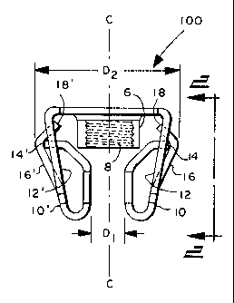
FIG. I is a central cross-section side view of an embodiment of the fastener
of the invention referenced by
numeral 100;
FIG. 2 is an edge view of fastener 100 taken along view line 2-2 in FIG. 1;
and
FIG. 3 is a central cross-section view of fastener 100 of FIG. 1 being secured
to a panel "P" by a threaded
member "T".
DESCRIPTION OF SOME PREFERRED EMBODIMENTS
In FIGS. 1 and 2, fastener 100 has a base portion 4 from one side of which
extends a hollow open-ended
barrel nut portion 6 having internal threads 8. A pair of resilient legs 10
and 10' respectively extend from
opposite ends of base portion 4 past and beyond nut member 6 and thence curve
inwardly towards each other
2

CA 02257062 1998-12-30
and thence upwardly towards base portion 4 in substantially parallel spaced-
apart relationship to each other
and to central rotational axis "C" passing through nut portion 6 shown in FIG.
1.
The upwardly substantially parallel sections of legs 10 and 10' are spaced-
apart from each other by the
distance "D 1" and are in substantial transverse relationship with base
portion 4 and then curve away from
each other and thence extend through open windows in each respectively
referenced by numerals 12 and 12'
in FIG. 1.
Legs 10 and 10', after having passed through windows 12 and 12', end in
respective free ends 14 and 14' that
are in contacting relationship with resilient fingers 16 and 16' that
respectively extend outwardly away from
each other from the bottom edge of windows 12 and 12' and thence curve
inwardly towards each other and
thence preferably pass through the upper region of windows 12 and 12' and end
in respective free-ends 18
and 18'.
As shown in FIG. 1, free-ends 14 and 14' of legs 10 and 10' contact fingers 16
and 16' at the location where
they turn or dog leg inwardly towards each other as previously described.
As shown in FIG. 1, the distance between the outer edges of legs 10 and 10' at
the location at which they
respectively turn inwardly towards each other prior to receiving a threaded
member such as threaded member
"T" in FIG. 2 is referenced by "D2" in FIG. 1.
As shown in FIG. 3, rotational advancement of threaded member "T" through nut
portion 6 causes the legs
and 10' to spread apart from each other from an original distance "D1" to a
distance "D3" which is the
same as the outside diameter of threads 22 of threaded member "T".
In spreading apart from each other, free-ends 14 and 14' urge the outer edges
of fingers 16 and 16' away from
each other from an initial spaced-apart distance "D2" referenced in FIG. 1 to
a distance "D4" shown in FIG.
4 causing the outer surface of the upper regions of fingers 16 and 16' to
engage opposite sides or edges of
opening 20 in panel "P" through which fastener 100 has been inserted with
sufficient force to secure fastener
100 within opening 20 to panel "P".
The distance "D4" can be expressed as being substantially equal to the
distance calculated from the
relationship "D2" + ("D3" - "D 1 ").
3

CA 02257062 1998-12-30
Although the fastener of the invention may be made from any suitable resilient
material or combination of
materials, it is preferably of a one-piece construction made form a suitable
spring steel.
Although the internal threads of nut portion 6 and the external threads 22 of
threaded member "T" may be
formed in any manner, one of the more preferred manners is when the internal
threads of nut portion 6 are
tapped machine threads and the external threads 22 of threaded member "T" are
machined threads operative
to threadingly engage the tapped internal threads of nut portion 6.
4

Representative Drawing
A single figure which represents the drawing illustrating the invention.
Administrative Status

2024-08-01:As part of the Next Generation Patents (NGP) transition, the Canadian Patents Database (CPD) now contains a more detailed Event History, which replicates the Event Log of our new back-office solution.

Please note that "Inactive:" events refers to events no longer in use in our new back-office solution.

For a clearer understanding of the status of the application/patent presented on this page, the site Disclaimer , as well as the definitions for Patent , Event History , Maintenance Fee  and Payment History  should be consulted.

Event History

Description Date
Inactive: Expired (new Act pat) 2018-12-30
Letter Sent 2010-01-04
Grant by Issuance 2008-04-15
Inactive: Cover page published 2008-04-14
Pre-grant 2008-01-29
Inactive: Final fee received 2008-01-29
Notice of Allowance is Issued 2007-08-15
Letter Sent 2007-08-15
Notice of Allowance is Issued 2007-08-15
Inactive: Approved for allowance (AFA) 2007-07-31
Amendment Received - Voluntary Amendment 2006-12-29
Inactive: S.30(2) Rules - Examiner requisition 2006-06-29
Inactive: Office letter 2005-02-24
Letter Sent 2005-02-23
Inactive: Single transfer 2005-02-23
Letter Sent 2005-02-23
Inactive: Office letter 2004-12-10
Inactive: Single transfer 2004-12-07
Letter Sent 2004-12-07
Inactive: Office letter 2004-12-07
Inactive: Single transfer 2004-12-07
Inactive: Multiple transfers 2004-11-02
Letter Sent 2003-08-27
Request for Examination Received 2003-07-31
Request for Examination Requirements Determined Compliant 2003-07-31
All Requirements for Examination Determined Compliant 2003-07-31
Letter Sent 2002-01-30
Inactive: Office letter 2002-01-30
Letter Sent 2002-01-30
Letter Sent 1999-10-20
Inactive: Office letter 1999-10-20
Letter Sent 1999-10-20
Inactive: Multiple transfers 1999-08-31
Inactive: Cover page published 1999-07-27
Application Published (Open to Public Inspection) 1999-07-22
Inactive: Correspondence - Formalities 1999-03-30
Inactive: IPC assigned 1999-02-15
Classification Modified 1999-02-15
Inactive: First IPC assigned 1999-02-15
Filing Requirements Determined Compliant 1999-01-29
Application Received - Regular National 1999-01-29
Inactive: Filing certificate - No RFE (English) 1999-01-29

Abandonment History

There is no abandonment history.

Maintenance Fee

The last payment was received on 2007-12-05

Note : If the full payment has not been received on or before the date indicated, a further fee may be required which may be one of the following

  • the reinstatement fee;
  • the late payment fee; or
  • additional fee to reverse deemed expiry.

Please refer to the CIPO Patent Fees web page to see all current fee amounts.

Fee History

Fee Type Anniversary Year Due Date Paid Date
Registration of a document 1998-12-30
Application fee - standard 1998-12-30
Registration of a document 1999-08-31
MF (application, 2nd anniv.) - standard 02 2001-01-01 2000-12-08
MF (application, 3rd anniv.) - standard 03 2001-12-31 2001-07-03
Registration of a document 2001-12-11
Registration of a document 2001-12-12
MF (application, 4th anniv.) - standard 04 2002-12-30 2002-07-30
MF (application, 5th anniv.) - standard 05 2003-12-30 2003-07-23
Request for examination - standard 2003-07-31
Registration of a document 2004-11-02
Registration of a document 2004-11-15
MF (application, 6th anniv.) - standard 06 2004-12-30 2004-12-02
MF (application, 7th anniv.) - standard 07 2005-12-30 2005-12-01
MF (application, 8th anniv.) - standard 08 2007-01-01 2006-12-05
MF (application, 9th anniv.) - standard 09 2007-12-31 2007-12-05
Final fee - standard 2008-01-29
MF (patent, 10th anniv.) - standard 2008-12-30 2008-12-01
Registration of a document 2009-10-29
MF (patent, 11th anniv.) - standard 2009-12-30 2009-12-01
MF (patent, 12th anniv.) - standard 2010-12-30 2010-11-30
MF (patent, 13th anniv.) - standard 2011-12-30 2011-11-30
MF (patent, 14th anniv.) - standard 2012-12-31 2012-11-30
MF (patent, 15th anniv.) - standard 2013-12-30 2013-12-16
MF (patent, 16th anniv.) - standard 2014-12-30 2014-12-22
MF (patent, 17th anniv.) - standard 2015-12-30 2015-12-21
MF (patent, 18th anniv.) - standard 2016-12-30 2016-12-19
MF (patent, 19th anniv.) - standard 2018-01-02 2017-12-18
Owners on Record

Note: Records showing the ownership history in alphabetical order.

Current Owners on Record
A. RAYMOND ET CIE
Past Owners on Record
JAMES RICHARD MUMBY
MICHAEL RICHARD DANBY
Past Owners that do not appear in the "Owners on Record" listing will appear in other documentation within the application.
Documents

To view selected files, please enter reCAPTCHA code :


To view images, click a link in the Document Description column. To download the documents, select one or more checkboxes in the first column and then click the "Download Selected in PDF format (Zip Archive)" or the "Download Selected as Single PDF" button.

List of published and non-published patent-specific documents on the CPD .

If you have any difficulty accessing content, you can call the Client Service Centre at 1-866-997-1936 or send them an e-mail at CIPO Client Service Centre.


Document
Description 
Date
(yyyy-mm-dd) 
Number of pages   Size of Image (KB) 
Representative drawing 1999-07-22 1 6
Description 1998-12-30 4 147
Abstract 1998-12-30 1 12
Claims 1998-12-30 1 50
Drawings 1998-12-30 1 23
Cover Page 1999-07-22 1 29
Description 2006-12-29 4 147
Representative drawing 2008-03-12 1 7
Cover Page 2008-03-12 1 33
Courtesy - Certificate of registration (related document(s)) 1999-01-29 1 115
Filing Certificate (English) 1999-01-29 1 163
Reminder of maintenance fee due 2000-08-31 1 110
Acknowledgement of Request for Examination 2003-08-27 1 173
Commissioner's Notice - Application Found Allowable 2007-08-15 1 164
Correspondence 1999-03-30 1 26
Correspondence 1999-09-29 1 9
Correspondence 2002-01-30 1 13
Correspondence 2004-12-07 1 22
Correspondence 2004-12-10 1 19
Correspondence 2005-02-24 1 20
Correspondence 2008-01-29 1 31