Note: Descriptions are shown in the official language in which they were submitted.
CA 022~7089 1998-11-19
W O97/45771 PCTrUS96107674
FOAM RESERVOIR FLUID TRANSFER ROLLER
AND METHOD OF MAKING SAME
Technical Field
The present invention relates to a novel roller.
More particularly, it relates to a novel fluid transfer
roller especially useful in offset printing.
Backqround of the Invention
Offset printing presses are provided with a
dampening system in which a fluid transfer roller
l~ transfers water to a plate cylinder.
The amount of water carried by the fluid transfer
roller and delivered to the plate cylinder can be
critical to the proper operation of the offset printing
press. When a fluid transfer roller does not pick up a
sufficiently even flat film of water, printing can occur
on areas not intended to be printed and there can be a
buildup of ink on the rollers which requires that the
offset printing press be shut down to permit cleaning.
Both printing errors and shutdowns, of course, are costly
and time-consuming. Conversely, when too much water is
delivered by the fluid transfer roller to the plate
cylinder, the ink can be overly diluted on the plate
cylinder and the ink may become emulsified. In addition,
it also can result in printing on areas which are not
intended to be printed. Once again the result is that
the efficiency and the performance of the printing system
suffers.
One type of fluid transfer roller used in the past
in dampening systems was made of steel and had a surface
which was either chromium plated or flame sprayed with a
CA 022S7089 1998-11-19
W O 97/4~771 PCT~US96107674
metal oxide, such as aluminum oxide, and which was
considered hydrophilic. This type of fluid transfer
roller did not have a reservoir and because it was
relatively heavy it required a large motor for operation.
In addition, such steel rollers tended to corrode which
could cause an ink buildup on the water rollers.
The most common currently used fluid transfer
rollers are elastomeric rollers which are covered with a
paper cover or cotton sleeve which creates a fluid
reservoir which allows for the proper continual wetting
of the non-image areas of the printing plate. The covers
and sleeves make the roller surface more hydrophilic.
The liquid storage capability of these covers and sleeves
provides rollers with a reservoir which allows for the
acceptance of excess water when not needed by the
printing plate and which supplies more water to the
printing plate when the demand is increased. Due to the
intermittent needs of the printing plate it is a
re~uirement that these rollers not only act as a
reservoir but that they also transfer water to the
printing plate when required.
One problem with using a paper cover or cotton
sleeve is that to install the cover or sleeve the press
has to be shut down, the elastomeric rollers removed from
the press, the covers or sleeves positioned over the
elastomeric rollers and then the rollers reinstalled back
into the press. Because of the considerable down time
which occurs, this can be a very costly procedure. In
addition, although the sleeves and covers are effective,
they are not very durable and they have to be replaced
often due to damage, ink contAmin~tion and/or wear.
CA 022~7089 1998-11-19
W O97/45771 PCT~US96/07674
A need exists for a fluid transfer roller which does
not possess the disadvantages of the prior art fluid
transfer rollers.
Summary of the Invention
The objects of the present invention are to provide
a novel fluid transfer roller for use in an offset
printing system that does not possess the disadvantages
of the prior art rollers and a method of preparing such a
roller.
The nove~ roller of the present invention comprises
a roller with an integral, foamed-in-place, cellular
outer layer having a density of about 5 to about 70
pounds per cubic foot (PCF), a compressibility of about 5
to about 100 psi and containing about 10% to about 90%
open cells at least some of which are interconnected.
The roughly spherical cells of the roller are
approximately .002 to .008 inches in diameter at and near
the outer surface and about .001 to about .004 inches in
diameter nearer the core. The open cells near the core
are connected to the exposed open cells at the surface by
capillary passages so that ~iquid can flow from the cells
near the core to the surface by capillary action. When
made by the method of the present invention, the
thickness and density of the outer layer can be varied to
supply the degree of reservoir desired.
In one embodiment of the invention, there is an
intermediate layer of elastomeric or foam material
between the cellular outer layer and the rigid core.
When foam is used as the intermediate layer it may be
desirable to include a barrier seal or layer to prevent
the intermediate layer from acting as a fluid reservoir.
CA 022~7089 1998-11-19
W O97/45771 PCT~US96/07674
In another embodiment of the invention, the cellular
outer layer is foamed-in-place on a rigid core.
The roller of the present invention provides several
advantages over prior art rollers. The open cells of the
outer layer of the cover act as capillaries which allow
water or an aqueous fountain solution to be distributed
evenly across the surface of plate cylinder. In
addition, the open cells below the surface of the layer
provide a reservoir for the water or fountain solution
and also make it less likely that ink will feed back into
the dampening system.
The foamed-in-place, outer layer is preferably made
of partially open-celled polyurethane foam which is very
durable and can be easily cleaned as part of a normal
press washing without any special procedures. In
addition, the polyurethane foam is not subject to ink
cont~min~tion in the normal printing environment. Thus,
it eliminates the need for special cleaning and
maintenance and the periodic need to replace and
condition covers or sleeves.
The method of preparing the roller of the present
invention comprises depositing the foam forming materials
from a dispensing head in the form of a stream onto a
metal, rubber, urethane or urethane foam covered
cylindrical core that is being rotated at a speed which
is adjusted based on roller size to m;ni mi ze the material
dripping from the surface. If needed, the core can be
first ground to facilitate the retention of a thin layer
of foam forming materials on the surface of the core. As
the stream of foam making material is being deposited by
the dispensing head onto the rotating core, the head is
also traversing the length of the core being coated. The
speed of the traverse movement is dictated by the size of
CA 022~7089 1998-ll-l9
W O 97/45771 PCT/US96/07674
the roller onto which the stream is being deposited.
Once deposited, the stream of foam forming materials
bonds to the core and slowly begin to rise and create a
layer of foam. The foam layer can be varied in thickness
and density by choice of material and/or substrate or
material temperature. If required, a second foam layer
can be applied to the first by allowing a period of time
between coatings for the first layer to partially cure.
Once the foam has cured to maturity the roller can be
ground to the desired size.
The foregoing and other objects and advantages of
the invention will be apparent to those skilled in the
art from the description of the preferred embodiments.
Brief Description of the Drawinqs
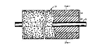
Fig. 1 is an elevational view, partly in section, of
a roller of the present invention;
Fig. 2 is an enlarged sectional view taken along
line 2-2 in Fig. 1;
Fig. 3 is a diagramic view showing the outer layer
of the roller of Fig. 1 being formed; and
Fig. 4 is a view taken along line 4-4 in Fig. 3.
Description of the Preferred Embodiment
In the preferred embodiment of the invention as seen
in Figs. 1 and 2, the roller 10 consists of a rigid
roller core 11, an intermediate support layer 12 and a
foamed-in-place, cellular outer layer 13 of polyurethane
foam containing about 30% to about 40% open cells and the
remainder closed cells. As seen in Fig. 2 the cells 14
CA 02257089 1998-11-19
W O 97145771 PCT~US96/07674
at the outer surface 15 can be different sizes than the
cells 16 near the core 11 and connected to them.
The preferred core 11 is a conventional steel roller
core. However, the core may be of other materials, such
as fiberglass, provided they possess the required
rigidity and other functional properties for use as the
core of a printing roller.
As seen in Figs. 3 and 4, in the preferred method of
preparing the roller of the present invention, the poly-
urethane foam forming materials are deposited through thehead 17 of mix metering equipment (not shown) at 75-90~ F
in the form of a stream at about 0.5 to about 1.0 pounds
per minute onto the cylindrical metal core 11 that is
being rotated at a speed which is adjusted based on
roller size to minimi ze the material dripping from the
surface. As the stream is deposited onto the rotating
core by the head 17, the head 17 is also traversing the
length of the roller or cylinder being coated, the speed
of traverse again dictated by the size of the roller 10
onto which the stream is being deposited. Once
deposited, the materials bind to the core 10 and begin to
slowly rise and create a layer of polyurethane foam that
cures at room temperature. The deposited foam layer can
be varied in thickness and density by choice of the
materials or temperatures. If required, a second foam
layer can be applied to the first by allowing a partial
curing time between coatings, usually 1-2 hours. The
reservoir capacity of the roller can be further
controlled by the wall thickness of the foam which is
left on the core after the foam layer has cured and the
roll is ground to achieve the diameter of the finished
roller.
CA 022~7089 1998-11-19
W O97/45771 PCTrUS96/07674
The grinding can be done once the foam has cured to
maturity. Although curing at room temperature for about
24 to about 48 hours is usually adequate, a two hour
212~ F postcure can be used to accelerate the development
of a full state of cure.
The choice of having a bare steel or a covered steel
core 11 is determined by the necessary resistance
required to keep the core material from corroding in the
environment in which the roller is being used. The use
of bonding agents or barrier coatings makes it possible
to improve this aspect of the rollers construction.
In addition to the preferred open-celled
polyurethane foam, any other type of foam material can be
used which possesses the desired properties and
durability under conditions of use.
The practice of the invention is further illustrated
by the examples which follow.
Example 1
Application of Foam Layer to Core
A core body of rigid steel about 50" in length and
2-5/8" in diameter is cleaned of all grease, oil and
foreign material. The cleaned core is then abraded using
sand paper, a rotary sander, a belt sander or it is
blasted with suitable grit to prepare the surface for
application of the primer and bonding agent.
To the cleaned, sanded or blasted core is applied a
primer coat which upon drying is then covered with a
bonding agent of various types, most usually also
urethane based. The primer materials are of the
polyvinyl butyral type that is cured with a phosphoric
acid catalyst, such as Conap AD-6, Chemlok 9944 Wash
CA 022~7089 1998-11-19
W O97/45771 PCTrUS96107674
primer or the like. The cover cement is of a wide
variety available, to be chosen from many such systems
supplied from ~ord Corporation or Dayton Products,
Division of Whittaker Corporation, these possibly being
Chemlok 210, Chemlok 213, Thixon 405 or the like. The
preferred system is the Chemlok g944 Wash Primer and
Chemlok 213.
Once the application of the primer/cover combination
has been completed, the roller is placed in a lathe and
begun rotating at 3-50 rpm about the center line axis of
the core. At that time, a two component urethane mixture
which forms a cellular foam is processed through a mix
metering machine and dispensed (0.5 to 1.0 pounds/minute)
on the core which is rotated at a speed which minimizes
the amount of material dripping from the core. The two
component foam systems are available from Polyurethane
Specialties Company, Lyndhurst, N.J., as their Milloxane
6000, 7000 or 7200 series of urethane foams, also other
materials are available from Miles, Inc., Plastomeric US
Inc., and others, or from in-house American Roller
compounding. At the same time as the urethane mixture is
being dispensed, the dispensing head travels traversely
across the face length of the core being covered (10 to
30 inches/minute). As the urethane mixture adheres to
the core, it gradually begins to blow and rise to a
height that will eventually represent the foam layer of
the roller. A second layer can be applied to the first
to achieve greater foam layer thickness after a waiting
period (e.g. 1 to 2 hours). The foam in question can be
between about 5 to about 40 pcf (free blow density), with
a 25% compressibility of about 5 to about 100 psi as
measured by ASTM D575-91.
CA 022~7089 1998-11-19
W O97/45771 PCT~US96/07674
Once the foam has cured to maturity and cooled, it
is ground to the required size. Although curing at room
temperature for 24 to 48 hours is usually adequate, a 2
hour postcure at 212~ F can be used to accelerate the
cure.
Example 2
A fluid transfer roller having a steel core which is
50" long and 2-5/8" in diameter prepared as described in
Example 1 is provided with a polyurethane foam outer
layer .050" thick, containing about 30% to about 40% open
cells and having a compressibility of 10-100 psi (ASTM
D575-91). The roller is used as a fluid transfer roll in
an offset printing machine. After 90 to 120 days, the
roller's performance was evaluated and found to be
generally superior to the paper covered roller it
replaced. In addition the roller showed no signs of wear
or of a need to be replaced.
It will be apparent to those versed in the art that
any number of foams could be developed and applied to the
core to form the cellular foam layer. These foams could
be either polyether or polyester in nature or of a
specialty type, all providing cellular construction and
the desired properties.
Those skilled in the art will recognize that a
number of changes can be made without departing from the
spirit and scope of the present invention. Therefore, it
is intended that the invention only be limited by the
claims that follow.