Note: Descriptions are shown in the official language in which they were submitted.
CA 022~73~4 1998-12-01
-
"Process and apparatus for producing camshafts"
TECHNICAL FIELD
The invention relates to a process for producing
elongated hollow bodies, in particular camshafts, and to an
apparatus for putting this process into practice.
PRIOR ART
Numerous processes for producing camshafts are known.
These fall mainly in two different groups.
The first group comprises the conventionally produced
camshafts, which are either forged or cast as blanks, both
as solid bodies and as chill castings. Both semifinished
products then have to undergo further processing steps,
namely first machining and then surface hardening and
tempering, followed by grinding of the bearing seats and the
cams. The disadvantages of camshafts produced in this way
include in particular heavy weight and consequently a high
moment of inertia, which adversely affects the bearings, for
example through the change in torque, as well as the
considerable cost of the steps of machining the blanks.
The other group includes composite camshafts in which
the cams are produced as individual parts and then fixed to
a shaft in various ways. Thus, for example, the cams may be
welded on, particularly to a hollow shaft, or else slid on
to a tube and shrunk thereon. For this last method of
production it is known to place the tube or hollow shaft,
after the cams have been slid on, in a suitably recessed
tool and to expand the tube using the high internal pressure
forming process (hydroforming process): the cams are
expanded elastically and the tube is expanded plastically so
that a firm seating of the cams on the tube or the
.. ...
CA 022~73~4 1998-12-01
hollow shaft is created by a force or interference fit.
In the hydroforming process the hollow tubular body to
be formed is subjected simultaneously to an internal
pressure and to an axial force acting on its ends. Suitable
pressure media are liquids or elastomers. The axial force is
as a rule applied by means of solid tools such as pistons,
dies and the like which act directly or indirectly on the
ends of the workpiece.
Examples of shafts joined or constructed in this way
are known from DE 34 09 541 A1 and DE 35 21 206 A1. Common
~ proposals is the troub1e and expense
\~
.. , ., . . ,. _
CA 022~73~4 1998-12-01
of the special production of the functional parts which are
to be fixed to the shaft, the individual production of
which, particularly in the case of cams, gives rise to
sub~stantial costs, quite apart from the fact that the whole
handling associated with the steps required for the joining
operation is complicated.
Furthermore a process is known from United States
spe~ification 2 222 762 in which tubular blanks are first
heated and then placed in a mould. The blank, rendered
easily deformable by the heating, is stabilised from inside
by means of a gaseous or liquid supporting medium. At the
same time axial forces, which are applied either by the
movable mould itself or by means of dies independent of the
mol~ld, press the blank into the mould, with the supporting
medlum serving to ensure that the heated blank does not
collapse. This process has the disadvantage that the blank
mus~- previously be heated so that the material acquires the
neeessary plasticity to be pressed into the mould. This
heating involves, as well as changes in structure, an
additional operating step, which adds to the cost of the
process. In addition the working pressure is only applied
thr~ qh the axial forces, which leads to a non-uniform flow
of material and hence to uneven distribution of stresses in
the workpiece.
Japanese specification JP 57 206530 A discloses a
process for producing a camshaft in which a previously
heated hollow body is pressed into a mould in one step by
means of a pressure liquid. Here, too, previous heating
takes place; furthermore, there is no axial feeding, which
likewise leads to a non-uniform flow of material, and in
add;tion there is no sequence of process steps, but only one
deforming step.
CA 022~73~4 1998-12-01
THE INVENTION
The object of the invention is to provide a process and
an apparatus for putting it into practice by means of which
elongated hollow bodies can be produced at lower cost not
only with savings in tools and working steps b~t also with
an increase in operating efficiency ~higher yield) and
avoidance of reductions in wall thickness.
~ his object is achieved by means of the features of the
ma~n claim, that is to say, in a fundamental departure from
the prior art the hydroforming process is not used to expand
a hollow shaft to create a force fit or, as in the case of
DE 35 21 206 A1, additional axial fixing, but to form the
projections themselves, preferably the cams, integrally from
tubular or section material - referred to hereinafter, for
the sake of simplicity, but without any limiting
significance, as "hollow bodies" or "hollow shafts" or
"shafts" - by bulging it out. Surprisingly, the successive
forming of the projections (cams) by bulging-out gives rise
to various possible ways of producing a one-piece hollow
bo~y which are both extremely economical and save processing
time.
3a
... ... . .
CA 022~73~4 1998-12-01
As a further aspect of the invention, a common feature
of the various possible embodiments is that the hollow shaft
is shaped in several steps, wherein the cams are
successively formed with respect to their shape and/or their
position on the shaft. In other words, as will also be shown
in detail by the following explanations, on the one hand the
cams may be brought stepwise to their final shape and on the
other hand they may be formed in succession in a desired
seqllence of their arrangement on the shaft. These two
possibilities can of course be superimposed.
Thus in a preferred embodiment of the invention the
cams are successively formed from the middle of the shaft to
its ends: it is particularly economical to do this in pairs.
Ano~her possibility is to form the cams from one end of the
shaft to the other. This procedure has the considerable
advantage of more economical processing, particularly in
dispensing with the individual production of cams, and of
the circumstance, provided by the calibration, that the
axial flow of material into the current deformation zone can
take place unhindered. In accordance with the invention the
feeding of material from the ends of the tube by the axial
application of force and the advancing movement is not
hindered by pairs of cams located ahead of it; that is to
say, tube material can be fed unhindered into the current
deformation zone. When this has been formed, the shaping of
the next pair of cams takes place. This has the advantage
that by the axially produced pressure stresses higher
dearees of deformation of the tube material can be achieved,
which lie above the rupture elongation of the material. In
addition the reduction in wall thickness in the deformation
zone (cams to be shaped) is substantially less, that is to
say, the wall thickness is more uniform, and higher
CA 022~73~4 1998-12-01
structural stability is obtained. For practical application
here are several possibilities.
Thus the cams may be formed in succession, singly or in
groups, in intended positions against the pressure of a
plurality of controllably withdrawable punches.
For this and the following possible embodiments there
is, in connection with the aforementioned possibility of
shaping the cams successively from the middle of the shaft
to its ends, the particular advantage that by the control of
the flow of the material into the inner region, i.e. into
the middle of the shaft, no great stretching of the material
takes place, since during the shaping of the inner cams the
flow of material as the material is fed axially is not
hindered by cams which have already been put in place.
Moreover it is possible thereby to produce camshafts from
materials having a lower ductility, having higher cam height
and with relatively numerous pairs of cams and bearing
seats, such as are needed for example for 12-cylinder
engines. There is also less upsetting of material at the
ends of the component and the wall thickness is more
uniform, with the further advantageous possibility of an
overall reduction in wall thickness if this should be
desired.
With the invention it is possible to use a very wide
variety of cold-workable materials, such as for example
"tailored blanks", "tailored tubes", and, as well as single-
layer materials, also dual materials such as, for example,
steel/steel or steel/aluminum combinations, hollow sandwich
bodies or coated hollow bodies. For the steel/aluminum
combination steel preferably constitutes the outer
supporting material and aluminum the inner one. Considerably
improved material properties are thereby
CA 022~73~4 1998-12-01
obtained: the steel jacket provides better wear, heat-
treatment and torque properties, while the inner aluminum
layer is a good supporting material and leads to weight
advantages. As a multilayer starting semi for forming in
accordance with the invention a shrunk-on fit combination
can be used, but it is also possible to produce this
semifinished product by extruding the components together or
by ~use of the continuous extrusion process.
In the aforementioned variants the punches may be
su}-jected to pressure at the desired time either singly or
in pairs, according to the application. In one possible
preferred embodiment they are controllable with regard to
travel and force by hydraulic cylinders associated with each
punch: in shaping from the middle to the ends of the shaft
no punches are needed for the inner cams or for the milled
recesses in the tool associated therewith, since that is
where the shaping of the cams begins, during which time the
punches in the other recesses are forced against the outer
wall of the hollow shaft, so that at these positions no
deformation of the shaft takes place. There the cams are
only formed at a later time.
As an alternative to the application of hydraulic
pressure to the punches or to their pistons or dies, the
travel control may also be effected mechanically, by means
of a V-rail moving substantially parallel to the
longitudinal axis of the hollow shaft and provided with
wedge cams acting directly on the die, so that suitable
movement of the V-rail brings about a travel adjustment of
the punch, i.e. also with this embodiment the recesses where
pressure is not to be applied and no cam is to be formed can
be selectively covered or the positions at which a cam is to
be formed can be exposed.
CA 022~7354 1998-12-01
The successive shaping of cams from the inside to the
ollt.side may also be effected, according to a particularly
preferred embodiment of the invention, by performing the
in~ividual production steps in different regions in the
tool. While it is then necessary to move the workpiece from
one locator in the tool to another between the individual
pro~ss steps, the design of the tool may nevertheless be
sirn~-ler and cheaper. In addition, in this case no active
e]ements such as punches or the like are provided, which
overall primarily becomes effective if there are no space
proi~lems, since in the case, for example, of six cams, with
shaping in pairs from the inside to the outside, three
workpiece locators are required in the tool, each provided
wit-h corresponding milled recesses.
Alternatively the locally selective shaping of the cams
may also take place through internal mandrels to be inserted
in l-he hollow shaft, which then, acting in a similar way to
th~ punches explained above, first hinder the shaping at
particular places, though in distinction to the punches they
act from the inside of the hollow shaft. Only the cams
currently being shaped (from inside to outside) are
(p~rtially) subjected to an internal pressure, so that only
there can a deformation take place: the remaining regions
ar~ not subjected to pressure, so that no deformation force
is acting there. In other words, here the hollow shaft is
not:, as in the case of the punches, supported against the
internal pressure; instead the internal mandrels prevent
pressure from being applied to the internal walls of the
hcllow shaft in the region of the recesses into which
de~ rmation is not yet to take place. Thus the mechanically
apF-lied axial pressure, together with the internal pressure,
only causes bulging-out and finally the desired shaping
CA 022~73~4 1998-12-01
where no internal mandrel protects the internal wall of the
hollow shaft from internal pressure and where one or more
milled recesses exist.
In practice it is preferred to use two internal
man~rels which are pushed into the hollow shaft at either
en~ and have an external diameter such that they can be
introduced or pulled into the pistons transmitting the
mec~anical axial forces to the ends of the tube. Thereby the
advantageous, locally successive shaping of the cams from
the middle of the shaft to its ends is again made possible.
The internal mandrels must, of course, be provided with
coaxial through passages so that the pressure medium can
reach the interior of the shaft.
This embodiment of the invention permits a
com~aratively large number of milled recesses to be
int~qrated in the tool with comparatively low tooling costs.
It should be mentioned that it is also possible, within
the ~scope of the invention, to start from a semifinished
prodllct which has been preformed using conventional
pro~esses, for example by upsetting or cross-rolling of a
hol~ow shaft. This offers the possibility of providing
accllmulations of material at the positions on the hollow
shaft where cams are to be shaped, in order to counter the
re~llction in wall thickness and any possible inadequate
ductility of the material.
BRIEF DESCRIPTION OF THE DRAWINGS
Further details and advantages of the invention will
now be given with reference to the accompanying drawings, in
which advantageous embodiments of the invention are shown.
In the drawings:
CA 022~73~4 1998-12-01
Fiq. 1 shows schematically, in a sectioned side view,
without auxiliary tooling, the basic form of a
tool, with a workpiece placed therein, in the
starting and final state;
Fi~. 2 shows, in more detail than in ~ig. 1, a tool
having in some mould nests punches which are
individually controlled with regard to travel and
force by means of hydraulic cylinders;
Fi~. 3 shows schematically a V-rail for control of the
ram of the punch shown in Fig. 2;
Fi~. 4 shows schematically, in plan view and sectioned, a
tool half having a plurality of locators for
stepwise processing of the workpiece with the
workpiece present in the respective shaped state;~5 Fiq. 5 shows schematically, in plan view and sectioned, a
tool half in a further variant application with a
partially processed workpiece (hollow shaft)
placed therein and the internal mandrels partly
shielding the inside wall of the hollow shaft; and~0 Fi~. 6 shows a preformed hollow shaft as a semi-
fabricated starting product, for use, for example,
in a tool as shown in Fig. 1.
MOI~ES OF PUTTING THE INVENTION INTO PRACTICE
Before going into detail about the illustrations, some
basic remarks must be made. Thus it should first of all be
noted that in Figs. 1 and 2, in the upper part of the
dr~wing the workpiece is shown in its final form, while in
t~ lower part the starting state, or in Fig. 6 an initial
in termediate state, is shown. Common to Figs. 1 to 5 is also
~ t they show schematically tools which are basically
sl];table for the internal high pressure forming process
CA 022~73~4 1998-12-01
(t~ so-called hydroforming process) and are preferably
divided horizontally into two parts. These exhibit one or
more recesses (tool interior engravings or mould nests) the
shape of which will be described below in more detail, into
which the workpiece to be deformed - in the present case a
ho]low shaft - is placed and is then subjected to forces
acting axially on its end faces by upsetting dies mounted
lat-~rally outside the tool and actuatable in known manner,
while at the same time a pressure medium is forced into the
int~?rior of the hollow shaft so that the workpiece is
subjected to a high internal pressure and an axial force
act-ing on the ends of the tube. This results in the desired
bu~ing-out in the closed tool. The lateral dies have a
diarileter such that they can be pushed into the tool and
UpS~-?t the hollow shaft, and have passages which run
CO-?,'~ ially through which the pressure medium can get into the
int-erior of the hollow shaft. The dies are provided at their
fre~ ends with sealing heads which serve to seal the
sernifinished product (pipe) at the pipe ends and to
intr~-dllce the axial forces into the workpiece and to supply
pr~ssure into the interior of the workpiece. Preferably the
pre~sure is applied through a pressure booster (designed
like a hydraulic cylinder) and can be increased (liquid in
the interior of the pressure booster is compressed) or
redllced (liquid is relieved).
In Fig. 1, greatly simplified to provide a general
pi(~ure, a tool is shown which comprises an upper tool half
1 arld a lower tool half 2, which in the closed state form
the cavity 3 as a mould for the final form of the camshaft.
It ~hould be noted - and this also applies to the other
~ strations of the other preferred exemplary embodiments -
that, purely for the sake of clarity, the individual cams
CA 022~73~4 1998-12-01
are here shown in a plane: obviously as a rule they are
radially angularly offset. At the positions where the cams
are ultimately to be situated the cavity 3 exhibits
co~responding milled recesses 4 (in the present case, merely
to ;llustrate the principle, only three in number) into
whi(~}l the corresponding wall regions of the hollow shaft are
pr~ssed. The milled recesses form part of the whole mould
neC~ in which a workpiece is placed.
In the lower half of Fig. 1 the initial state of the
hollow shaft 5 is shown, while the upper illustration shows
lt-~. final state with the finish-formed cams 6, i.e. the
int~rally produced camshaft in accordance with the
inv~rltion. The numeral 7 indicates the lateral pressure dies
wi~h their die heads 8, which as shown in the left-hand
se--t-ional drawing have a coaxial through passage 9 through
whi~ the pressure medium penetrates into the interior of
t}-~ hollow shaft 5.
In this embodiment the hollow tube 5 is placed in the
to(ll 1/2 having the camshaft geometry to be formed and is
def(-rmed by internal high pressure with axial material feed.
That- is to say, the hollow shaft 5 is brought continuously
fr-~m its starting state into its final state by applying
axial pressure by the pressure dies 7 against the end faces
o~ t:he hollow shaft 5 and at the same time supplying the
pr~ssure medium through the passages 9. Under the influence
of these two superimposed forces the deformation to the
finaL state shown takes place as the pressure dies advance
;n'o the interior of the tool.
For the following embodiments the same reference
nllrn~rals are used as for the corresponding parts in Fig. 1.
In the embodiment shown in Fig. 2 the tool, as
previously explained, consists of an upper tool half
CA 022~73~4 1998-12-01
1 .~rld a lower tool half 2, whose cavity 3 is shaped in the
desired geometry for the camshaft. In this embodiment six
mi]led-out recesses 4 for shaping six respective cams are
pr--vided in the tool. For simplicity, the pressure medium
su~ ly passages 9 in the dies 7/8 are not shown. In the
ct~rrently outer milled-out recesses 4a and 4b, i.e. those
siTIlated toward the ends of the shaft, respective punches
l]a arld llb, here shown only diagrammatically, are provided,
whi~T~ as shown by the double arrows are movable in the
milled-out recesses substantially at right angles to the
lorl~itudinal axis of the hollow shaft 5, through respective
rarTIs l3a and 13b connected to respective hydraulic cylinders
12a and 12b. The punches lla and llb can thereby be
co~lrolled as to their travel and force: in the starting
position they are situated with their front faces in the
up~r position shown in the drawing, i.e. up against the
out~r wall of a hollow shaft 5 placed in the tool. The two
inT~r milled-out recesses 4 do not have any punches.
The process proceeds as follows. Since the four punches
lla and b are in their advanced starting position, the inner
cams 6 are first shaped with axial feeding of shaft
maierial, without the flow of material being hindered by
forrnation of the outer cams, i.e. those lying nearer the
en(is of the shaft. When shaping of the two inner cams 6 is
complete, the cylinders 12b lying first outwardly of the
finished cams, and consequently the punches llb, are
retracted and the cams 6b are next shaped. Here, too, the
axial flow of material is again not hindered, since the
sh.lping of the end cams 6a does not yet occur. In the last
se~iion of the hydroforming the punches lla are retracted
an(~ the corresponding cams 6a are shaped.
Instead of the hydraulic actuation of the
CA 022~73~4 1998-12-01
p~]rl<hes lla and llb their control and movement can also be
eff~ted mechanically. For this a V-rail 14 is shown in Fig.
3 which has a number of wedge cams 15a and 15b which
corresponds to the number of punches lla and llb, arranged
to correspond to the positions of the punch rams 13a and
13~?. In this case the V-rail 14 is mounted in the region of
thr~ hydraulic cylinders 12a and 12b and is movable parallel
to the longitudinal axis of the hollow shaft 5, with the
we(~qe cams 15a and 15b acting directly on the corresponding
rams ]3a and 13b. In this case only a single hydraulic
cyli~lder (not shown) is required, which moves the V-rail 14
lrl the direction of the horizontal double arrow in Fig. 3.
Il) the position shown in Fig. 3 the rams 13a and 13b, on
wh;r-h the wedge cams 15a and 15b act directly, are shown in
th~ir advanced position, i.e. in the position in which the
intl~r cams 6 are first shaped.
By moving the V-rail 14 towards the left (in Fig. 3)
wil'l simultaneous application of internal pressure, the
put~-}les lla and llb in Fig. 2 are forced downwards, since
th~ir rams 13a and 13b can yield downwards along the slopes
of the wedge cams 15a and 15b.
Using such a V-rail, a direct control in the sense of
th~ process explained previously in connection with Fig. 2
is r~ossible, since, as Fig. 3 likewise shows, the inner V-
rails have a shorter face, i.e. in the case of a leftwardmc?~ment the rams 13b arrive in the region of the slopes of
thr wedge cams 15b before the rams 13a, so that the forming
of t~he cams 6b then takes place first of all, before that of
the cams 6a begins: this takes place at the time at which
th~ rams 13a arrive in the region of the slopes of the wedge
CarTlS 15a.
To further improve the flow of material in the
CA 02257354 1998 - 12 - 01
shaping of the inner cams 6 punches may also be provided in
t~l~ milled-out recesses 4 which are controlled in a
corresponding manner through rams by cams (not shown here)
whictl lie correspondingly between the wedge cams 15a and
15~.
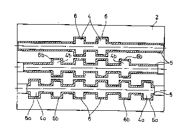
Fig. 4, in which the lateral dies 7/8 are not shown,
sh-~ws a particularly preferred embodiment of the invention,
it~ which in the lower tool half 2 (as shown in the plan
vi-~w) three mould nests of different geometry (different
numhers of milled-out recesses) for the workpiece are shown,
wit~ a workpiece 5 as made in the respective step in each
mollld nest. The deformation into the individual form nests
car~ be performed simultaneously or successively.
Fig. 4 makes it clear that the fabrication of a
carTlshaft 5 provided with six cams takes place in three
st~es. In a first process step the hollow shaft 5 in the
to~? mould nest in Fig. 4 is deformed until the two inner
carlls 6 have been shaped. The semifinished product thus
f~?rmed is then moved into the mould nest shown below, which
is F~rovided with two additional milled-out recesses 4b into
wlli~h in this second stage the cams 6b are then deformed.
Finllly the hollow shaft 5 is then moved into the bottom
mol~ld nest shown in Fig. 4, equipped with six milled-out
re~sses 4, 4a and 4b, in which the deformation into the
fir~al state then takes place.
Fig. 5 - a likewise preferred embodiment - shows a
l(~wer tool half 2 for producing a camshaft with six cams 6,
of which the two inner ones have already been fabricated.
Wi~l this tool, too, the cams 6 are made successively from
t~ inside to the outside, for which purpose two internal
man(~rels 16 are used which in the state shown of an
ir~l~rmediate production stage have been pushed so far
14
CA 022~73~4 1998-12-01
into the end of the hollow shaft 5 that in the interior of
the hollow shaft they protect from internal pressure the
re~;ons which are only to be deformed into the outer milled-
ollt recesses 4a and 4b later in the process. For this
purpose the internal mandrels have an external diameter
wh;(-l~ allows them to be pushed telescopically into the
h~llow shaft 5 with a suitable clearance from its inner
wall. At their free, inner end the internal mandrels 16 are
ea(il provided with a head seal 17 or V-shaped sealing rings,
w~ seal the pipe or the hollow shaft 5 as soon as a
pr~ s~re is produced in its interior. The higher the
pJ ~ sure, the greater does the sealing force of the wedge
se~ g rings become: the sealing force is thus generated by
t}l~ internal pressure.
In this case the dies 7/8 are on the one hand, as in
t~ embodiments already described, formed with an external
di~meter which allows them to be introduced into the tool
re(ess, i.e. a diameter which approximately corresponds to
th~ external diameter of the hollow shaft 5, but in
d;~-inction from the previous embodiments they have an
er~l~rged internal passage having a diameter so large that
t}l~' ir-ternal mandrel can be moved telescopically inwards and
outwards therein. The dies 7/8 can thus still exert their
axi~l force on the end faces of the hollow shaft 5, while
t~ internal mandrels 16 are simultaneously moved inside
tl~ . The coaxial passage 9 for the pressure medium is now
sit~1ated in the respective internal mandrels 16. This can be
s~ , in detail from the sectional representation in the left
hal~ of the drawing.
With this concept the following process sequence can be
ac~ieved. First of all the internal mandrels 16 are moved
o~lt of the dies 7/8, which have their ends against
~ .. .... .
CA 022~73~4 1998-12-01
th~ hollow shaft, and moved into the hollow shaft 5 into the
posit-ion shown in Fig. 5. This can be done by suitable means
(n--l shown here) provided at the outer ends of the hollow
dies 7/8, for which purpose the internal mandrels can
prc~ject through the dies 7/8 for example as far as their
ol]~-er ends. Under the local internal pressurisation which
now occurs the two inner cams are shaped in the manner
s}l~ ~wr~ .
Next the internal mandrels 16 are withdrawn outwards
f~ enough for the region of the next milled-out recess 4b
tc- ~e exposed, so that the internal pressure can now act on
t~ regions of the hollow shaft, which are then deformed
int(~ these milled-out recesses to form the cams 6b, with
si~mlLtaneous axial feeding of material from the ends of the
t~ , the internal mandrels 16 also being moved inwards by
th~ amount of the material feed in order to avoid friction
be~ween the V-shaped sealing ring 17 on the internal
m~ rels 16 and the inner wall of the tube.
After the shaping of this second pair of cams 6b the
irlt~rr-al pressure is relieved, so that the sealing force on
tlle V-shaped sealing rings 17 is reduced to a minimum (the
it~'? rent elasticity of the sealing rings). The internal
m~ irels 16 are then moved still further outward and the
ne~it pair of cams 6a are shaped.
In this version, too, an optimum material feed can be
a-~lieved, since in each process step - the cam shaping takes
pl~fe, as already explained several times in connection with
t~ embodiments previously described, stepwise from the
mi(i(~le of the shaft to its ends - the material can be fed
un~ iered from the ends, since in the regions which are not
s~ jected to pressure the deformation is not yet taking
P~ '( ~.
16
CA 022~73~4 1998-12-01
Merely to amplify the many and diverse possibilities of
ap~lication of the process in accordance with the invention,
in ELg. 6 a semifinished starting product for a hollow shaft
5 i~ shown which is to be shaped to give a camshaft with six
carms and is preformed into the state shown in Fig. 6 by
co~ ntional processes such as upsetting of the hollow
shaf~-, cross-rolling etc, with accumulations of material 19
bei~ formed at the position at which the cams are to be
S}lrll~d in order to counteract the reduction in wall
t~ kness and any inadequate ductility of the material. Such
a c-~mifirlished starting product is suitable, for example,
ff~ rocessing in a tool such as that shown in Figs. 1 and
2, arld also reduces the material flow on account of the
a~ nlllations of material.
IMI~IJ~ RIAL APPLICATION
The invention is useful for the production especially
o~ ~]ongated hollow bodies, which have many and different
applications in the automobile industry.