Note: Descriptions are shown in the official language in which they were submitted.
CA 02257490 l998-l2-03
W O 97/47126 PCTrUS97/09645 -
TITLE:
METHOD AND APPARATUS FOR REMOTE TELEMETERING
8UB8mU~E 8HEET n~lllE 211~
CA 022~7490 l998-l2-03
W O 97/47126 PCTnUS97/09645-
CONTINUING DATA:
This is a continuation-in-part of commonly-owned, copending
U.S. ~rovisional Patent Application No. 60/019,135 filed 03 Jun
96.
TECHNICAL FIELD OF THE INVENTION
The invention relates to telemetering systems for
monitoring remotely located equipment, and more particularly to
retrieving status, usage, and accumulated totals from remotely
located utility monitoring devices such as power meters, gas
meters, water meters, etc., especially via a common carrier
communications medium such as the public switched telephone
network (PSTN). Other application areas include home security,
home health care systems and home transaction processing
equipment.
BACKGROUND O~ THE INVENTION
Remote monitoring (or "telemetering") of utility metering
equipment is of great interest to public utilities that provide
electric power, gas and water to businesses and residences.
Nationwide, public utilities employ thousands of workers
expressly for the purpose of going from building to building and
reading meter totals. The trips made by these "meter readers"
are time-consuming and costly, considering the number of meters
which must be read, the number of employees involved, and the
number of vehicles which must be maintained and kept on the
road. Further, visual meter reading is quite error-prone,
especially on analog "dial" type meters, since dial pointer
positions are often visually ambiguous.
Accordingly, public utilities have long recognized that a
cost-effective, automated, remote meter-reading mechanism could
make meter total collection easier, faster, less costly, and
more accurate. A number of attempts to provide remote meter
reading capability have been made, but most have proven either
SUB8IITUTE ~REEI ~RUIE ~
CA 022~7490 1998-12-03
WO 97/47126 PCTrUS97/09645 -
clumsy or unworkable for a variety of reasons.
One telephone-based technique employs a scheme whereby
meter data reading is initiated using special alert tone
signalling over standard telephone lines. This technique has
the advantage that it generally does not disturb normal
telephone function, but it has the very great disadvantage that
it requires specially equipped line cards at the central
telephone office to transmit and receive the meter signal. Full
implementation of a meter reading system employing this
technique would require a massive investment in special-purpose
telephone equipment before it could achieve widespread use.
Other telephone-based techniques have employed more
conventional in-band signaling mechanisms (e.g., modem) for
meter communications. Although these techniques have the
advantage of being compatible with conventional telephone line
cards, they have proven unworkable because they interfere with
the customer's normal telephone service.
Public utilities are generally under extreme pressure to
keep rates under control. A technically viable approach to
automated meter reading may become completely impractical if
implementation would result in a rate hike to end users
(customers of the utilities).
Evidently, there is a need for a cost-effective, fully
automated mechanism for reading utility meters and other data
collection devices remotely.
SllMMARY OF THE INVENTION
Although the foregoing discussion has been directed
primarily to reading utility meters via a switched telephone
network, those of ordinary skill in the art will immediately
understand and appreciate that the same basic issues apply to
8UB$mUrE 8HE~ p~UlE 21~
CA 022~7490 1998-12-03
W O97/47126 PCT~US97/09645-
monitoring any kind of remote telemetry data via any of a
variety of different communications media, including but not
limited to, communications via power lines, cable television
(CATV) wiring, commercial broadcast media, fiber optics, and
low-power radio.
It is therefore an object of the present invention to
provide a technique for remote telemetry which permits
inexpensive, automatic data collection from a widespread
plurality of remotely located metering devices such as electric
power usage meters, water usage meters, or gas usage meters.
It is a further object of the present invention to provide
a technique for remote telemetry which improves overall data
collection accuracy.
It is a further object of the present invention to provide
a technique for remote telemetry which eliminates or
substantially reduces the need for direct visual reading of
remotely located metering devices.
It is a further object of the present invention to provide
a technique for remote telemetry of metering devices on
customersl premises which utilizes existing communications media
and existing customer-premises wiring.
It is a further object of the present invention to provide
a technique for remote telemetry of metering devices on
customers' premises using common-carrier communications media,
such as the public switched telephone network (PSTN), while
utilizing unmodified, existing common-carrier equipment and
procedures.
It is a further ob~ect of the present invention to provide
a technique for remote telemetry of metering devices on
8U1 8TITU~E 8~ UlE 2~1)
CA 022~7490 1998-12-03
W O97/47126 PCTAUS97/09645-
customers' premises via an existing communication medium, such
as the customers' telephone service, without perceptibly
interfering with normal operation of the communication medium.
~According to the invention, a system for retrieving data
from remotely located monitored devices, such as utility
~metering devices, is implemented by providing remote monitor
systems at each of a plurality of monitor sites. Each monitor
site has one or more monitored devices from which data is
required. For example, a monitored device might be an electric
meter, and the data provided by the electric meter would be, for
example, usage totals and peak electric load information.
The remote monitor system interposes itself between a
communications medium (e.g., a switched telephone network) and
any and all communications devices (e.g., telephones, answering
machines, modems, fax machines, etc.) which would ordinarily be
connected directly to the communications medium. It is intended
that the remote monitor system "share" the communication medium
with the communications devices in a transparent fashion. This
is accomplished by means of a relay or other logical switching
mechanism by which the communications devices are normally
connected through the remote monitor system to the
communications medium. This logical connection between the
communication devices and the communications medium is broken
only when the remote monitor system needs to communicate via the
communications system.
It is also within the scope of this invention that the
remote monitoring system takes control of the house phone wiring
using ABO (automatic back off) to isolate the house phone
wiring from the telephone company. The communications devices~
connection to the communications system is not required all of
the time. By having the ability to control this connection,
important new low-cost digital gateway services to and within
SU~TllUTE SH0 PUIE 2~
CA 022~7490 1998-12-03
W O 97/47126 PCTnUS97/09645-
the home are facilitated.
According to an aspect of the invention, each remote
monitor system is equipped with an identifying mechanism whereby
it can identify the source of any incoming communications,
before responding thereto. When the communications medium is
a switched telephone networks, this identifying mechanism can
be provided in the form of a caller ID (CID) decoder, whereby
the remote monitor system receives caller ID (CID) codes for
incoming calls.
According to another aspect of the invention, identifying
codes for incoming communications are compared by the remote
monitor system with one or more pre-stored identifying codes.
The pre-stored codes are associated with authorized servers.
The remote monitor system will respond only to those identified
servers. This provides security by preventing access to
metering devices by unauthorized persons. This also permits the
operation of the remote monitor to remain "transparent" or
invisible to users of the communications devices (e.g.,
telephones) at the monitor sites, by permitting the remote
monitor system to ~intercept" incoming calls from servers
attempting to retrieve data from the monitored device(s). These
intercepted calls are not passed through the remote monitor
system, and are therefore unnoticed by the user of the
communications devices. The aforementioned relay (or other
logical switching device) disconnects the communications
device(s) (e.g., telephones) while the remote monitor system is
communication with the server.
According to another aspect of the invention, the remote
monitor system includes means for monitoring the communications
devices attached to it for attempted use. In the case of
telephone equipment, this amounts to a loop current monitor
whereby the remote monitor system can detect the on-hook/off-
SUUTITUTE 8~ ~llUlE 21n
CA 022~7490 1998-12-03
WO97/47126 PCT~S97/09645-
hook status of the attached communications devices.
The remote monitor system grants ultimate priority to the
communications devices (e.g., telephones). It accomplishes this
by continually monitoring usage attempts (e.g., off-hook
condition) thereof. If the remote monitor system is busy
communicating with a server via the communications medium when
a usage attempt is made by a communications device, it
immediately terminates communications with the server and
logically re-connects the communications device through to the
communications medium. In this manner, the existence and
function of the remote monitor system remains invisible to users
of the communications devices.
In a full implementation of the inventive telemetering
system, there can be many servers and a great many monitor
sites. For example, each monitor site might be a building or
a residence having a water meter, and electric meter, and a gas
meter. As is the case in many locations, the water company, gas
company, and electric company may be completely independent of
one another for the purposes of meter reading and customer
billing. Each utility company would have its own server and
would provide its own metering device at each remote monitor
site. However, for the sake of simplicity and economy, the
utility companies might share a single remote monitor system at
each monitor site which is set up to collect data from all of
the metering devices at the monitor site. Additionally, other
service providers may share the remote monitor in other
applications such as home health care, equipment reading, or
security systems equipment reading.
Alternatively, multiple remote monitor systems at a monitor
site could be "cascaded" with one feeding into another which in
turn feeds into another, etc., since the operation of the remote
monitor systems is transparent and each remote monitor system
SUI~IlUTE SRET n~UlE 2~ -
CA 022~7490 1998-12-03
W 097/47126 PCTrUSg7/09645-
responds only to incoming communications for which it is
programmed. In this case, one metering device would be
connected to each remote monitor system, and each monitor system
would be programmed to respond only to the server associated
with the metering device for which it gathers data.
The inventive technique has the very great advantage that
it is inexpensive, utilizes existing communications facilities
(e.g., for telephone applications, no special line cards or
switch equipment is required), and is completely invisible to
users of the communications medium which is used for remote
telemetering.
Other objects, features and advantages of the invention
will become apparent in light of the following description
thereof.
BRIEF DESCRIPTION OF THE DRAWINGS
Reference will now be made in detail to preferred embodiments
of the invention, examples of which are illustrated in the
accompanying drawings. Although the invention will be described
in the context of these preferred embodiments, it should be
understood that it is not intended to limit the spirit and scope
of the invention to these particular embodiments.
Figure 1 is a block diagram of a system for retrieval of
data from one or more remote data gathering devices (monitored
equipment), according to the invention.
Figure 2 is a block diagram of a modem portion of the
system of Figure 1, according to the invention.
Figure 3 is a schematic diagram of a Line Reversal and Ring
Detector portion of the system of Figure 1, according to the
invention.
8UB~TITU~E 8HEE~ IIIUIE ~
.
CA 022~7490 1998-12-03
W O 97/47126 PCT~US97/09645-
Figure 4 is a block diagram of a microcontroller portion
of the system of Figure 1, according to the invention.
Figure 5 is a block diagram of a remote telemetering syste~
wherein a plurality of servers can access a plurality of remote
monitors, according to the invention.
DETAILED DESCRIPTION OF THE INVENTION
According to the invention, a system employing a modem
having a caller ID recognition feature incorporated (e.g.,
integrated) therein is useful, for example, for gathering data
from a remote data source via digital communications over a
communications medium, with the meter responding only to a
predetermined (preset) requester (caller).
The remote data source is, for example, an electric utility
meter measuring residential power consumption and patterns of
usage.
The communications medium is suitably a telephone line,
power line, radio, or mixed media (e.g., low-power radio signal
relayed to central office by a set of signal
collectors/repeaters), etc.
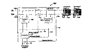
Figure 1 is a block diagram of a system 100 for gathering
data from one or more remotely located data sources (monitored
equipment), according to the invention. As shown in the Figure,
the system 100 employs conventional telephone wiring already
installed at the site of the remotely located data sources for
communications therewith. A remote monitor 102, is installed
in a location at a remote site in a location where it can
retrieve data from the monitored equipment. Connections to the
existing telephone wiring are made via an automatic back-off
Data Access Arrangement 104 (ABO-DAA). The ABO-DAA 104 is
SU11$~1TUTE $HEI 11 UIE 211~
CA 022~7490 1998-12-03
W O97/47126 PCT~US97/09645-
connected by standard tip (106a) and ring (106b) connections to
existing telephone wiring to the public switched telephone
network (PSTN). A standard DAA 108 (Data Access Arrangement)
within the ABO-DAA 104 provides a controller 110 in the remote
monitor 102 with access to the tip and ring telephone
connections 106a and 106b. The controller 110 includes a modem
function, tone generation and decoding, caller ID (CID)
decoding, control and status leads, and one or more interfaces
to external monitored equipment (the aforementioned data
source(s) ). The controller can optionally include storage means
for storing one or more preset authorized caller identification
numbers and one or more callback telephone numbers.
The controller 110 communicates over the PSTN via the
standard DAA 108, which acts as a protection and isolation
circuit between the PSTN and the controller 110, and is
essentially transparent to the communications and signaling
mechanisms (i.e., modem, CID decoder, and tone generation and
decoding) within the controller.
The controller 110 interrogates the one or more monitored
devices via one or more sets of communications lines 124.
Although the communications lines are generally shown in Figure
1 as wired connections, it will be readily appreciated by those
of ordinary skill in the art that these communications lines 124
can be provided in the form of any suitable form of digital or
analog communications with the monitored devices including, but
not limited to, light beam communication, microwave
communication, spread spectrum or other form of radio
communications, or fiber optics.
A monitored device can be fully digital, storing its own
totals, counts and other data in digital form, in which case the
communications line(s) associated with the digital monitored
device provide digital communications means whereby the
SUB8TITUTE SREET ~IUIE 2~ -
.
CA 022~7490 1998-12-03
W O 97/47126 PCTrUS97/09645 -
controller can retrieve the stored value. Alternatively, a
monitored device can be little more than a transducer, in which
case the communications lines provide for suitable monitoring
of the monitored device by the controller 110, which must
interpret signals from the monitored device and develop its own
digital representations thereof and must accumulate its own
totals and counts therefor.
Transducers, digital data collection devices and techniques
and circuits for interfacing thereto are well known to those of
ordinary skill in the art. The present inventive technique is
not dependent upon any specific transducer or data collection
device interface, and those of ordinary skill in the art will
immediately understand how to provide communications lines to
any suitable transducer or data collection device. Therefore,
further detailed discussion of the monitored devices is beyond
the scope of the present specification, and omission of such
discussion should not be seen as limiting. It is fully within
the spirit and scope of the present invention to provide access
to any suitable data collection device or transducer.
The AB0-DAA 104 further includes a relay 112 or other
suitable switching device which permits "normal", existing
customer premises connections 116a and 116b to the PSTN to be
disconnected, under control of the controller 110 via a relay
control line 114. The existing connections 116a and 116b
normally provide connection between customer premises telephone
equipment ~shown in Figure 1 as "Household Phone #1" 118a and
"Household Phone #2" 118b.)
Those of ordinary skill in the art will immediately
appreciate that the function of the relay 112 can be
accomplished equally well by electronic switching means
effecting a "logical" connection/disconnection between
communications devices on the customer premises and the
11
$1BmTU~E S~ RUIE 2~
CA 022~7490 1998-12-03
W O 97/47126 PCTrUS97/09645-
communications medium instead of a direct connection. It is
readily understood ~that this form of "logical" connection is
functionally equivalent to a direct electrical connection and
that no significant difference would be perceived between the
two types of connection.
The ABO-DAA 104 further includes an impedance monitor 120,
connected to the controller 110 by an off-hook detect line 122.
The impedance monitor 120 measures the impedance seen across the
customer premises connections 116a and 116b to determine the on-
hook/off-hook status of the customer premises telephone
equipment (e.g., phones 118a and 118b).
The standard data access arrangement 108 preferably uses
no magnetic components (e.g., transformers or inductors), and
is tuned for best economics and operation at a data rate of
which is matched to the transmission characteristics of the
controller, described in greater detail hereinbelow with respect
to Figure 2.
The ABO-DAA 104 has an "automatic back-off" (ABO) feature
which is illustrated in Figure 1. In Figure 1, a telephone line
(e.g., a conventional pair of lines, labeled "tip" 102a and
~ring" 102b) is connected to telephone sets 118a and 118b in the
household (residence) via the relay 112 (connection relay).
Normally, the connection relay 112 is closed. When the remote
monitor is "using" the phone line (during a data session with
a server), the connection relay 112 will be open (as shown).
When someone picks up any of the phones (e.g., 118a or
118b) at the customer premises, this is sensed by the phone line
loop impedance monitor 120 connected to the phone side of the
connection relay 112 (as opposed to the incoming line side)
across the household telephone wiring (via tip and ring
connections 116a and 116b) to which the phone instruments 118a
12
8U~lllUlE 811E~ IllUlE 21~
CA 022~7490 1998-12-03
W O 97/47126 PCTrUS97/09645-
and 118b are connected, and a signal 122 is provided to the
controller. In response to the signal, the remote monitor
controller will immediately terminate the data session with the
server, hang itse~f up, and close the connection relay 112 so
that the users may use their phones (118a, 118b) in a normal
manner. The remote monitor 102 will reestablish the data session
~ with the server (including re-dialing the server) when the
impedance monitor 120 senses that the user has terminated their
phone call. In this manner, the customer has full access to the
telephone line at any time, even if it is already in use by the
remote monitor 102. As a result, the existence of the remote
monitor 102 is essentially invisible to the user. At worst, the
user will perceive a slight delay in receiving a dial tone when
the remote monitor 102 is forced to abort a data session, due
primarily to the amount of time required to cancel the call.
In most cases, this delay will be imperceptible to the user, and
will occur only very rarely.
Figure 2 is a block diagram of a modem function with
integrated caller ID detection 200 (hereinafter referred to as
a "CID modem) within the controller 110. The CID modem 200
connects to the PSTN via a tip connection 202a and a ring
connection 202b. These connections are made via the standard
DAA (108, Fig. 1), which is functionally transparent to the CID
modem 200. A transmit and receive filter 204 eliminates out-
of-band telephone line noise for communication with the CID
modem 200. Modem signals 206 to and from the transmit and
receive filter 204 connect to a modem 208, by which digital
transmit information can be modulated for transmission via the
tip and ring connections 202a and 202b to the PSTN, and by which
signals received via the tip and ring connections 202a and 202b
can be demodulated to provide digital receive information.
The transmit and receive filter 204 provides receive
signals 210 to DTMF (Dual Tone Multi-Frequency) and CP (Call
13
8UBSTlllITE SIEE~ l! UIE 2a)
CA 022~7490 1998-12-03
W O97/47126 PCTrUS97/09645-
Progress) tone decoders 212 by which call progress and DTMF
tones may be monitored. A DTMF and CP tone generator 216
provides tone signaling signals 214 to the transmit and receive
filter for transmission via the tip and ring connections 202a
and 202b.
The modem 208 exchanges digital transmit and receive
signals 220 with a serial communications port 222 which receives
serial data to be transmitted via the modem 208 over a serial
digital transmit data line 224a and which transmits digital
receive data from the modem 208 over a serial digital receive
data line 224b.
A control interface 226 provides a set of control and
status leads 230 by which a microcontroller (described
hereinbelow with respect to Figure 4) can control the functions
within the CID modem 200. Via control and status signals 228,
the control interface provides control and receives status
information to/from the serial port 222, the modem 208, the DTMF
and CP Tone Decoders 212, the DTMF and Tone Generator 216, and
a Line Reversal and Ring Detector 232.
The Line Reversal and Ring Detector 232 monitors signals
across the tip and ring connections 202a and 202b, and
determines if a line reversal (i.e., a DC polarity switch from
positive to negative) or a ringing signal (e.g., an AC voltage
of about 90 volts RMS), is present, and make that determination
available via the control interface 226.
Figure 3 is a schematic diagram showing basic components
of a Line Reversal and Ring Detector 300 (hereinafter LRRD) in
greater detail. The LRRD 300 connects to the tip and ring
connections 202a and 202b (see Fig. 2). A series RC circuit
comprising a capacitor 302a and a resistor 304a connect the tip
connection 202a to a first AC input 306a of a full-wave bridge
14
SU18TITUTE 8HE~ n~UIE 2~)
CA 022~7490 1998-12-03
W O 97/47126 PCTrUS97/09645-
rectifier 306. Similarly, ano~her series RC circuit comprising
a capacitor 302b and~a resistor 304b connect the ring connection
202b to a second AC input 306b of the full-wave bridge rectifier
306. Because of the RC input connections (i.e., 302a, 304a and
302b, 304b) to the bridge rectifier, DC signals are blocked
while AC and transient signals are passed. A negative output
306c of the bridge rectifier 306 is connected to a reference
ground voltage. A positive output 306d of the bridge rectifier
306 is connected to a resistive divider comprising two resistors
308 and 310. The resistive divider produces scales down the
voltage at the positive output 306d of the bridge rectifier 306
(which may reach voltages well in excess of 100 volts) to a
level which can safely be applied to an input of a threshold
detector 312. The threshold detector 312 is designed with a
degree of hysteresis so that its output will not "bounce" back
and forth when there are small noise voltages at its input. The
output of the threshold detector drives a transistor 314
connected such that a drain terminal thereof is effectively
grounded when the output of the detector 312 is active and is
at a high impedance otherwise. The transistor output (drain)
connects to an integrating RC network comprising a resistor 316
and a capacitor 318. One end of the resistor 316 is connected
to a positive voltage (VDD) and the other end of the resistor
is connected to one end of the capacitor 318, to the output
(drain) of the transistor 314, and to an input of a second
threshold detector. An output 322 of the second threshold
detector 320 provides a Ring Detect Signal (RDET).
In standard telephone circuits, ringing is accomplished by
a 90 Volt RMS AC signal applied across the tip and ring
connections 202a and 202b by the telephone service provider.
Ordinarily, this ring signal is used to drive a ringer of a
telephone. The RC divider (resistors 308 and 310) is set up so
that a ringing waveform will provide sufficient voltage to
exceed the minimum threshold of the threshold detector 312. As
SU~8~11U1E $HEE~ nlULE 21~
CA 022~7490 1998-12-03
W O97/47126 rcTrusg7/og645.
long as the ringing signal is present across the tip and ring
connections 202a and 202b, on each half cycle thereof, the
threshold detector 312 causes the output (drain) of the
transistor 314 to become grounded, thereby collapsing the
voltage across the capacitor 318 and causing the second
threshold detector 320 to indicate that ringing is in progress
via its RDET output 322. The time constant of the integrating
RC network (resistor 316 and capacitor 318) is selected such
that the ring detect signal output 322 will be maintained
between half-cycles of the ringing signal. When the ringing
signal stops, the voltage at the junction of the integrating RC
networks (resistor 316 and capacitor 318) rises past a threshold
voltage of the second threshold detector 320 (which takes longer
than one half cycle of the AC ringing signal), and the RDET
output 322 of the second threshold detector becomes inactive.
Line reversal is detected in much the same fashion. A line
reversal occurs when the steady state DC voltage across the tip
and ring signals 202a and 202b (normally 48 volts DC under no-
load conditions) is caused to reverse polarity. Since the tip
and ring signals 202a and 202b are AC coupled to the LRRD 300,
this is seen effectively as a 96 volt transient, to which the
LRRD reacts as if it was a single half cycle of ringing signal,
thereby producing a short pulse, the width of which is
determined primarily by the time constant of the integrating RC
circuit (resistor 316 and capacitor 318).
In CID applications, the timing of the ringing signal and
of line reversals are used to indicate when CID signaling data
is present across the tip and ring connections 202a and 202b.
The CID data is encoded as tones, which are detected and decoded
by the tone detectors and/or modem circuitry within the CID
modem.
16
S1~8TllUlE 8REr ~IIUIE 2~
CA 022~7490 l998-l2-03
W O97147126 PCTrUS97/09645-
The details of telephone line interface and signaling
characteristics, including CID signaling, are well established
and well known to those of ordinary skill in the art and will
not be elaborated upon further herein. This should not be
interpreted as limiting in any way to the spirit or scope of the
present invention.
Figure 4 is a block diagram of a microcontroller portion
400 of a controller (see 110, Fig. 1). A microcomputer 402
operating under stored program control, controls operation of
the microcontroller 400- The microcontroller 400 is equipped
with a serial interface 404 by means of which the
microcontroller 400 communicates with the serial port 222 on the
modem 208, one or more interfaces 406 to monitored devices which
are communicated with via communications lines 124 (see Fig. 1),
non-volatile memory 408 for storing configuration information,
totals, valid caller ID's, etc., and a control interface 410 by
which the microcomputer 402 can manipulate and monitor signals
on control and status leads 230 (see description hereinabove
with respect to Fig. 2). Not shown, but assumed to be present
within the microcomputer 402 are program memory and data memory.
The program memory can be read-only, or re-writable. If re-
writable memory is employed, it is possible to send program
updates to the microcomputer 402 via the communications medium
(PSTN, as shown and described hereinabove).
Figure 5 is a block diagram of a remote telemetry system
500, wherein a plurality of servers 502 (S1, S2, S3 ... Sn) are
each connected via a modem with CID capability 504 to the Public
Switched Telephone Network 510, or other suitable, addressable
communications medium. A plurality of remote monitors 520 of
the type described hereinabove with respect to Figures 1-4
(i.e., having CID capability) are individually connected to the
PSTN 510. Preferably, the remote monitors are co-located with
and connected to at least one remotely readable metering device
17
$Wm~UTE ~HE~ nlUlE 2~
CA 022~7490 1998-12-03
W O 97/47126 PCTrUS97/09645
(e.g., monitored device connections 124, Fig. 1) and other
telephone equipment (see, e.g., 118a, 118b, Fig. 1) at the
location of the remote which would otherwise be connected
directly to the PSTN is instead connected to the PSTN through
an ABO-DAA (see, e.g., 104, Figure 1) portion of the remote
monitor 520.
Reference numbers for the following description are taken
from Figure 1, unless specified otherwise.
In an example of use, a system 100 of the type shown in
Figure 1 would be installed at an electric user's premises and
connected to a suitable electric usage meter to be monitored by
an electric utility company. One or more Caller Identification
numbers corresponding to the telephone number or numbers from
which the electric utility company would call the electric user
to interrogate the electric usage meter would be pre-stored
within the remote monitor 102. At an appropriate time, the
electric utility company would place a telephone call to the
electric user, and the controller 110 in the remote monitor 102
would respond when there is a match to the preset caller ID
number within the controller (see description hereinabove with
respect to Figure 4 and non-volatile memory 408).
The caller ID feature within the remote monitor 100
identifies the caller as an authorized automated meter reading
station, and answers the call. When the ~Imeter call" is
answered by the modem, the modem disconnects the ordinary phone
(e.g., 118a, 118b) by opening the connection relay 112 and does
a quick transfer (burst) of information that has been stored to
the server at the electric utility company (see Fig. 5), then
terminates the call, hangs up (goes on-hook) and restore the
connection from the ordinary phone (e.g., 118a, 118b) to the
PSTN (via tip and ring connections 102a, 102b) by once again
closing the relay 112. Preferably, the relay would be arranged
18
8U~8111UrE8REEl (RULE 2~)
.. .. .
CA 022~7490 1998-12-03
WO97/47126 PCTrUS97/09645-
such that in the event of loss of power to the remote monitor
102, the relay 112 would go to its closed state until power is
restored.
For quickly transferring manageable amounts of data, the
modem (208, Figure 2) preferably operates at or above 1200 baud.
This is suitable for automatic meter reading (AMR), such as for
electric, gas and water.
The invention also provides a gateway to low cost digital
services to the home.
A single remote telemetry system (e.g., 100) incorporating
a CID Modem (e.g., 200, Fig. 2) (collectively referred to herein
as "remote monitor") can be accessed by various (N) servers
(e.g., power company, water company, telephone company, bank,
etc.) which can call into a home through the telephone lines to
"wakeup" the remote monitor. When the remote monitor receives
the wakeup call, it doesn't answer the phone, but can (through
caller ID (CID) ) identify that Server X is waking it up. The
remote monitor then calls the server as it looks up the server's
phone number (which may be one of several stored numbers,
identifiable by virtue of the aforementioned CID).
For enabling digital services (conducting data sessions),
including AMR, between servers and users, an exemplary activity
flow would be:
By using CID, the server rings the remote monitor at the
customer s premises to wake it up.
By using CID, subsequent data transactions are
authenticated, as described hereinabove.
(By using CID Time/Date fields, a real time clock in the
19
8UWTllUrE SHEE~ ~UIE 2~)
.
CA 022~7490 1998-12-03
W O97/47126 PCTAUS97/09645-
remote monitor can be synchronized with a more accurate (e.g.,
astronomical) clock at the server's location.)
Next, a call is initiated by the remote monitor to the
server which woke it up. If the customer has blocked his (or
her) own CID, this may be automatically unblocked for purposes
of the data session. (Customers' permission would be required
and would be obtained to unblock their CID for the
aforementioned servers.)
Preferably, the servers each have an "800" or "888" (i.e.,
toll free) number. In this manner, the customer who has the
remote monitor installed will not have to pay for the remote
monitor's calls (to servers). Often, the simple act of calling
an 800 number will automatically unblock a CID feature which has
been blocked ~for privacy reasons) by the user, thus allowing
the CID to operate for the purpose of identifying the user to
the called server.
At the server, the inbound (customer's) call CID
information can be used as a form of password to allow only
subscribing customers to proceed with a data session.
At the server, the inbound call CID information can also
be used to track any telephone number changes where the remote
monitor is located. For example, a new tenant moves into an
apartment unit and has a new telephone number installed. When
the remote monitor calls in, the serial number will identify
where the call is coming from (its address), and the CID
information will identify what the new telephone number is. This
information can be compared with telephone directory
information, and enable the server to automatically track a
new telephone number, from CID information, of the remote
monitor.
81~1~ S~ 211D
CA 022~7490 1998-12-03
W O97/47126 PCT~US97/09645.
Generally, the remote monitor includes a microprocessor
with a memory architecture and OS (operating system) kernel
which permits remote downloading over phone lines without
disrupting continuous operation of previously loaded and running
applications
For example, consider the case where the remote monitor has
an AMR application running. It is counting pulses from a meter
and accumulating them. A new application is downloaded which is
to allow the customer to go on TOU (time of use) billing. The
new software may be downloaded without losing any real-time
counts or any previously collected data, or without overwriting
installation variables such as the customer's phone number, etc.
A suitable encryption function, such as NBS DES, allows for
secure transmission of data. As a remote monitor may be
collecting data for several independent services and sending the
data to several different servers (or to securely partitioned
areas within a single server), each data set may have a
different encryption key. The system is able to manage multiple
keys such that each data environment has a uniquely secure data
communications path.
For example, each of the power company, the water company,
the gas company, and the bank (i.e., each of the several
servers), would have a separate and distinct key.
It is within the spirit and scope of the present invention
that a handheld device, similar to a television remote
controller or a small wall-mounted or desktop box, allows the
customer to call for some of the services that have been
subscribed to, which are activated through the remote monitor.
The customer could readily scroll through a list of services
that are available, and then initiate a trigger which causes the
remote monitor to start an inbound call to the appropriate one
21
SUB8mUTE ~HEE~ ~ULE 21~)
CA 022~7490 1998-12-03
W O 97/47126 PCTrUS97/09645-
of many subscribed servers. In this scenario, the handheld
device would simply be handled by the microcontroller as another
monitored device wherein the communication line is an infrared
(or other suitable) remote control interface, for which specific
actions and responses are programmed into the microcontroller.
It is within the scope of the invention that a smart telephone
perform the aforementioned functions of a handheld device.
For example, the customer may want to know the cost of the
last phone call. Selecting the trigger for the phone company,
would cause that information to be downloaded to the user. The
information would be displayed on an LCD display, or the like.
Another example would be to trigger paying a utility bill
which would cause a call to the Bank's server. Another example
would be to order a taxi, or to order a wake-up call. The
_ particular server which "sees" the call from the remote monitor
would verify the user through the user's CID, to ensure that the
user is a subscriber to the desired service.
It is fully within the spirit, scope and intent of the
present invention that some or all of the functions of the
remote monitor (see 102, Fig. 1), especially the remote monitor
controller (see 110, Fig. 1) can be implemented in the form of
one or more integrated circuit chips.
CONCLUSION:
As described hereinabove, automatic back-off (ABO) is an
important feature of the invention, making operation of the
remote monitor "transparent" to the user.
The above, and other objects, features, advantages and
embodiments of the invention, including other (i.e., additional)
embodiments of the techniques discussed above may become
apparent to one having ordinary skill in the art to which this
22
SU~ IE SIIEE~ ~IUIE 28~
. ~ . . .
CA 02257490 1998-12-03
W O 97/47126 PCTrUS97/09645-
invention most nearly pertains, and such other and additional
embodiments are deemed to be within the spirit and scope of the
present invention.
8U~TlllIIE 8RET ~RWE 21~