Note: Descriptions are shown in the official language in which they were submitted.
CA 022~7~84 1998-12-29
Acoustic Transducer System
Background of the Invention
The invention relates to an acoustic transducer system
including an electromechanical transducer, a circular
flexural vibrating plate coupled to the electromechanical
transducer and so configured that it is stimulated to higher
order flexural vibration at the system operating frequency,
at which nodal lines form on the flexural vibrating plate
between which first and second antinodal zones are located
oscillating alternatingly opposite in phase so that the
flexural vibrating plate emits sound waves into a
transmission medium bordering one side of the flexural
vibrating plate or is stimulated to flexural vibration by
sound waves arriving via the transmission medium, and
including means for influencing the sound radiation by the
flexural vibrating plate.
Acoustic transducer systems of this kind are used more
particularly as sound transmitters and/or sound receivers for
echo ranging wherein the travel time of a sound wave emitted
by a sound transmitter to a reflecting object and the travel
time of the echo sound wave reflected by the object back to
the sound receiver is measured. For the known speed of sound
the travel time is a measure of the distance to be measured.
The frequency of the sound wave may be in the audible range
or in the ultrasonic range. In most cases ranging is done in
accordance with the pulse delay method in which a short sound
pulse is emitted and the echo pulse reflected by the object
is detected. In this case the same acoustic transducer system
may be used alternatingly as the sound transmitter and sound
receiver.
CA 022~7~84 1998-12-29
One broad field of application of this sonic ranging
technique is level sensing. For this purpose the acoustic
transducer system is located above the material to be sensed,
above the highest level of the material anticipated, so that
it radiates a sound wave downwards onto the material and
receives the sound wave reflected upwards from the surface of
the material. The measured travel time of the sound wave then
indicates the distance of the material surface from the
acoustic transducer system, and for a known mounting level of
the acoustic transducer system the level to be sensed may
then be computed.
For sonic ranging over long distances high-performance
acoustic transducer systems having a good efficiency are
needed so that the intensity of the received echo signal is
still sufficient for analysis. The efficiency depends mainly
on two factors:
1. on how well the acoustic transducer system is adapted to
the impedance of the transmission medium;
2. on the directivity of the acoustic transducer system in
transmitting and receiving sound waves.
The flexural vibrating plates used in known acoustic
transducer systems serve for impedance matching. In level
sensing the transmission medium for the sound waves is
gaseous, e.g. air, this also applying to many other fields of
application. Conventional electromechanical transducers, such
as piezoelectric transducers, magnetostrictive transducers,
etc. have as a rule an acoustic impedance which is very
different to that of air or other gaseous transmission media.
This is why they serve in known acoustic transducer systems
merely for stimulating the large surface area flexural
vibrating plates forming the actual sound radiators or sound
receivers and result in good impedance matching to air or
other gaseous transmission media.
. . . _
CA 022~7~84 1998-12-29
As regards the desired directivity large surface area
flexural vibrating plates would appear to be likewise of
advantage since it is known that pencilling a radiation lobe
is the narrower the greater the extension of the radiation
surface area in relation to the wavelength. This is hampered,
however, by the problem that the antinodal zones oscillating
alternatingly opposite in phase emit sound waves opposite in
phase causing interference with each other in the case of
acoustic transducer systems incorporating a flexural
vibrating plate exhibiting higher order flexural vibration.
To avoid this unfavorable radiation pattern it is known
from "The Journal of the Acoustical Society of America, Vol.
51, No. 3 (Part 2), pages 953 to 959, to configure the
portions of the flexural vibrating plate corresponding to the
antinodal zones alternatingly differing in thickness. This
difference in thickness is so dimensioned that the sound
waves emitted by the thicker portions receive a phase
rotation through 180~. The sound waves radiated from all
antinodal zones are then in phase so that the radiation
pattern features a marked radiation maximum in the axial
direction in the form of a pencilled lobe. Producing such a
flexural vibrating plate is, however, complicated and
expensive. Furthermore, the acoustic transducer system
equipped with such a flexural vibrating plate has a very
narrow band since phase rotation through 180~ occurs only for
a highly specific frequency as dictated by the structure of
the flexural vibrating plate, this being the reason why it is
not suitable for pulsed operation.
In an acoustic transducer system known from European
Patent EP 0 039 986 the portions of the flexural vibrating
plate corresponding to the alternating antinodal zones are
likewise configured so that the sound waves generated by
every second antinodal zone receive a phase rotation through
180~, resulting in the sound waves emitted from all antinodal
CA 022~7~84 1998-12-29
zones being substantially in phase. For this purpose a low-
loss acoustic propagation material is applied to the
corresponding portions of the emitting surface area of the
flexural vibrating plate in such a thickness that the desired
phase rotation is achieved, closed cell expanded plastics
materials or non-expanded elastomers being proposed as the
low-loss acoustic propagation material used for this purpose.
This material needs to be cut out corresponding to the shape
of the antinodal zones and bonded to the flexural vibrating
plate, thus resulting in problems when the acoustic
transducer system is exposed in operation to mechanical
stresses or chemical influences as is particularly the case
in level sensing. The bonded plastics parts are susceptible
to damage and are only weakly resistant to many chemically
aggressive media. Furthermore, they increase the risk of
encrustations of dusty, powdery or tacky material, this
impairing reliable functioning.
In an acoustic transducer system known from German
patent 36 02 351 a sonic beam shaper is provided to influence
the sound emitted, comprising sound wave barriers which are
impervious for sound waves, located spaced away from the
flexural vibrating plate and acoustically decoupled therefrom
in front of antinodal zones oscillating in phase relative to
each other, whilst portions which are pervious for sound
waves are located in front of the remaining antinodal zones
oscillating opposite in phase relative to the former
antinodal zones. The sonic beam shaper has the effect that
only in-phase sound waves are radiated by the flexural
vibrating plate whilst the sound waves opposite in phase
thereto are suppressed by the sound wave barriers.
Summary of the Invention
The object of the invention is to provide an acoustic
transducer system of the aforementioned kind featuring good
CA 022~7~84 1998-12-29
directivity whilst being highly insensitive to noise,
soilage, encrustations and the effects of aggressive media.
This object is achieved in accordance with the invention
in that in the second antinodal zones oscillating in phase
with respect to each other and opposite in phase in relation
to the first antinodal zones one mass ring each is arranged
on the rear side of the flexural vibrating plate facing away
from the transmission medium concentrically to the
centerpoint of the flexural vibrating plate.
In the acoustic transducer system in accordance with the
invention the mass rings arranged in the second antinodal
zones oscillating in phase have the effect that these
antinodal zones oscillate with a reduced amplitude, whilst at
the same time the oscillation amplitude of the first
antinodal zones oscillating opposite in phase to the second
antinodal zones is increased. The sound waves emitted by the
alternating antinodal zones, opposite in phase to each other
and resulting in interference with each other thus greatly
differ in amplitude so that the weaker sound waves are
suppressed and only the sound waves in phase having a
considerable intensity are propagated in the main direction
of radiation perpendicular to the flexural vibrating plate.
This results in a radiation pattern having a pronounced
directivity in the main direction of radiation. In this
arrangement the face side, exposed to the environment, of the
acoustic transducer system is formed exclusively by the
smooth and flat front side of the flexural vibrating plate
whilst all means of influencing sound radiation are arranged
on the rear side of the flexural vibrating plate, protected
from the environment, this resulting in the acoustic
transducer system being highly insensitive to soilage,
encrustations and the effect of aggressive media. The
acoustic transducer system is thus particularly suitable for
use under rough environmental conditions as are encountered,
more particularly, in industrial applications.
CA 022~7~84 1998-12-29
Advantageous aspects and further embodiments of the
invention are characterized in the sub-claims.
Brief Description of the Drawings
Further features and advantages of the invention read
from the following description of example embodiments as
shown in the drawings in which:
~ig. 1 is a schematic section view of an acoustic
transducer system in accordance with the invention,
~ig. 2 is a plan view of the rear side, facing away from
the transmission medium, of the flexural vibrating
plate of the acoustic transducer as shown in Fig. 1,
~ig. 3 is a schematic illustration for explaining the
functioning of the flexural vibrating plate of a
known kind of acoustic transducer system,
~ig. 4 is a schematic illustration for explaining the
functioning of the flexural vibrating plate of the
acoustic transducer system as shown in Fig. 1, and
~ig. 5 is an illustration of a modified embodiment of the
acoustic transducer system as shown in Fig. 1.
Detailed Description of the preferred Embodiments
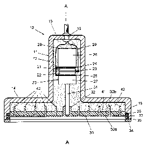
Referring now to Fig. 1 there is illustrated an acoustic
transducer system 10 including a housing 11 having a tubular
section 12 which is closed at one end by a bottom 13 and
merges at the opposite open end into a flared section 14
having the shape of a shallow dish with a rim 15. Applied to
an opening in the bottom 13 is a cable lead-through 16. The
whole housing 11 is rotationally symmetric to its centerline
, . . ~ ~ .
CA 022~7~84 1998-12-29
A-A so that the rim lS of the flared section 14 is right
circular.
Arranged in the tubular section 12 is an
electromechanical transducer 20 which in the example
embodiment shown is a piezoelectric transducer, consisting of
two piezo elements 21 and 22 located sandwiched between two
outer electrodes 24, 25 with the insertion of a middle
electrode 23. The sandwich block consisting of the piezo
elements 21, 22 and the electrodes 23, 24, 25 is clamped in
place between a supporting compound 26 and a coupling
compound 27. The two outer electrodes 24 and 25 are
electrically connected to a common lead 28. The middle
electrode 23 is connected to a second lead 29. The two piezo
elements 21, 22 are thus electrically connected in parallel
whilst being located in series mechanically.
Arranged in the flat flared section 14 is a thin
circular flexural vibrating plate 30 which is mechanically
connected to the electromechanical transducer 20 by a rod 31.
The rod 31 protrudes into the axial hole of a bushing 32
provided in the center of the flexural vibrating plate 30 and
is fixedly connected thereto by suitable means, for instance,
by being screwed, pressed, welded or soldered into place. The
flexural vibrating plate 30 is located spaced away from the
bottom of the flared housing section 14, the diameter of the
flexural vibrating plate being slightly larger than the inner
diameter of the rim 15 and slightly smaller than the inner
diameter of a recess 33 formed in the face end of the rim 15.
In the recess 33 the rim of the flexural vibrating plate 30
is clamped in place by means of a retaining ring 34 between
two O-rings 35 and 36. The retaining ring may be secured in
any suitable way to the rim 15, for example by being screwed,
welded, soldered or bonded in place. The O-rings 35 and 36
serve to isolate structure-borne noise between the flexural
vibrating plate 30 and the housing 11 whilst simultaneously
preventing ingress of undesirable foreign matter into the
CA 022~7~84 1998-12-29
interior of the housing 11 round about the rim of the
flexural vibrating plate 30.
The front side 30a of the flexural vibrating plate 30 in
contact with the transmission medium (e.g. air) into which
sound waves are to be radiated or from which sound waves are
to be received is totally smooth and flat, whereas arranged
on the rear side 30b, facing away from the transmission
medium, of the flexural vibrating plate 30 located in the
interior of the flared housing section 14 are circular
concentric mass rings 40, these rings being evident in
section in Fig. 1 and in a plan view on the rear side 30b of
the flexural vibrating plate 30 from Fig. 2. The mass rings
40 may be connected to the flexural vibrating plate 30 by any
suitable means. They may be fabricated, as evident from the
embodiment as shown in Fig. 1, and just like the central
bushing 32 in one piece with the flexural vibrating plate 30,
for example, by being milled out of a solid metal plate.
However, they may also be fabricated as separate parts which
are then secured to the flexural vibrating plate 30, for
example, by welding, soldering or bonding, in this case too,
the mass rings 40 preferably being made of metal. The
sections of the rear side 30b of the flexural vibrating plate
30 not occupied by the bushing 32 and the mass rings 40 are
covered by an expanded plastics material 41, the thickness of
which is less than the height of the mass rings 40. All of
the remaining interior of the housing 11 is filled with a
potting compound 42 consisting of a high-damping plastics
material in which also the sections of the mass rings 40
protruding from the expanded plastics material 41 are
embedded. The expanded plastics material 41 prevents the
potting compound 42 from coming into contact with the
flexural vibrating plate 30. The expanded plastics material
41 may consist for example of polyethylene or polybutadiene.
For the potting compound 42 use may be made of the
polyurethane-based two-component casting resin known by the
. . .
CA 022~7~84 1998-12-29
name of "Nafturan" (trademark) or the silicone rubber known
by the name of "Eccosil" (trademark).
The acoustic transducer system 10 as shown in Fig.
serves the purpose of converting electrical oscillations into
sound waves transmitted in the direction of the centerline A-
A, i.e. perpendicular to the plane of the flexural vibrating
plate 30, or of converting sound waves coming from this
direction into electrical oscillations. The transceiving
direction as shown in Fig. 1 is located perpendicularly under
the acoustic transducer system, this corresponding to the
usual method of installation when the acoustic transducer
system is employed as a kind of echo sounder for level
sensing. In this application the acoustic transducer system
is mounted above the highest level anticipated and the sound
waves travel through the air downwards until they impact the
surface of the material where they are reflected to return to
the acoustic transducer system as an echo signal. The spacing
between the surface of the material and the acoustic
transducer system materializes from the travel time of the
sound waves, it being from this spacing that the level may be
computed. For measuring the travel time the sound waves are
normally emitted in the form of short pulses and the delay
until the echo pulses arrive is measured. In this case the
acoustic transducer system as illustrated may be used
alternatingly as the sound transmitter and as the sound
receiver.
In other applications, for instance in ranging, the
acoustic transducer system may of course be operated in any
other direction as required.
In all cases, for achieving a long range with best
possible efficiency, i.e. for receiving sufficiently strong
echo signals with as low a transmission power as possible,
two requirements need to be satisfied:
CA 022~7~84 l998-l2-29
1. good adaptation of the acoustic transducer system to the
acoustic impedance of the transmission medium, e.g. air;
2. good directivity, i.e. pencilling the sound wave beam as
sharply as possible in the desired direction of
transmission, i.e. in the direction of the centerline A-
A.
To satisfy the first requirement the flexural vibrating
plate 30 is used as sound radiator. When an electric
alternating voltage is applied to the electrodes 23, 24, 25
via the leads 28, 29 the piezo elements 21, 22 execute
thickness resonances which stimulate the coupling resonator
tuned to the elements 26, 27 into longitudinal resonance
vibrations which are transferred to the rod 31 causing it to
execute longitudinal vibrations in the direction of the
centerline A-A. The system operating frequency, i.e. the
frequency of the electrical alternating voltage and thus the
frequency of the mechanical vibration generated by the
piezoelectric transducer is substantially higher than the
flexural vibration natural resonance frequency of the
flexural vibrating plate 30 so that the flexural vibrating
plate 30 is excited by the rod 31 into higher order flexural
vibration. The large surface area flexural vibrating plate 30
stimulated to higher order flexural vibration results in a
good impedance matching to the transmission medium, i.e. air
or any other gaseous transmission medium.
Satisfying the second requirement is the task of the
mass rings 40 applied to the rear side 30b of the flexural
vibrating plate 30. The function of the mass rings 40 and the
effect they produce will now be discussed with reference to
Figs. 3 and 4.
Referring now to Fig. 3 there is illustrated
schematically the vibrational response of a section of a
conventional type flexural vibrating plate stimulated into
CA 022~7~84 1998-12-29
.
higher order flexural vibration, consisting of a thin metal
plate smooth and flat on both sides and consistent in
thickness. The straight line M identifies the center plane of
the flexural vibrating plate in its resting position. In the
stimulated condition concentric nodal lines K form on the
flexural vibrating plate which remain during vibration in the
resting position on the center plane M. The spacings of the
nodal lines K are dictated by the system operating frequency;
all nodal lines have the same spacing ~/2 from each other
corresponding to half the wavelength of the standing flexural
wave formed on the flexural vibrating plate 30 at the system
operating frequency. Located between the nodal lines K are
annular diaphragm sections forming alternating first
antinodal zones B1 and second antinodal zones B2. All first
antinodal zones Bl oscillate in phase. All second antinodal
zones B2 oscillate likewise in phase, but opposite in phase
to the first antinodal zones B1. The vibration condition of
the antinodal zones B1 and B2 as evident from Fig. 3 at a
point in time corresponding to the maximum deflection in one
direction is represented by a solid line whilst the vibration
condition at a point in time corresponding to the maximum
deflection in the opposite direction, i.e. after a change in
phase of 180~ is represented by a broken line. The amplitudes
of the deflections are of the same size for the antinodal
zones B1 and B2, they being indicated exaggerated for better
clarity.
Each antinodal zone produces a sound wave which is
propagated in the adjoining transmission medium. As regards
the desired directivity there is, however, the problem that
the sound waves generated by neighboring antinodal zones are
each opposite in phase, these sound waves alternatingly
opposite in phase in the case of the conventional-type
acoustic transducer system as shown in Fig. 3 being the same
in amplitude so that they cancel each other out in the
desired direction of propagation perpendicular to the plane M
of the flexural vibrating plate. Such a sound wave
CA 022~7~84 1998-12-29
distribution produces no pronounced directivity in the axial
direction located perpendicular to the flexural vibrating
plate; instead the directivity pattern features strong
radiation side lobes located concentric to this axial
direction and further weaker side blips. It is due to this
poor directivity that the majority of the emitted acoustical
energy is lost in particular over longish sensing distances,
without being returned to the acoustic transducer system. The
acoustic transducer system has the same directive pattern in
reception as in transmission.
Referring now to Fig. 4 there is illustrated the
vibration response of the flexural vibrating plate 30
provided with the mass rings 40 as shown in Fig. 1. The mass
rings 40 are arranged so that in vibration at system
operating frequency one mass ring 40 each is located in the
middle of every second antinodal zone B2 whilst the first
antinodal zones Bl are free of mass rings 40. Due to the
additional mass the second antinodal zones B2 oscillate with
a reduced amplitude about the center plane M of the flexural
vibrating plate 30. The spacing between two nodal lines K
between which a second antinodal zone B2 having a mass ring
40 is located is reduced to ~/2-~, and the spacing between
two nodal lines K between which a first antinodal zone Bl is
located is correspondingly increased to ~/2+~. This results
in the first antinodal zones B1 oscillating with a
substantially larger amplitude than the second antinodal
zones B2 and accordingly the sound waves generated by the
first antinodal zones B1 have a substantially larger
amplitude than the sound waves generated by the second
antinodal zones B2. The sound waves opposite in phase and
parallel to each other are thus no longer able to fully
cancel each other out; instead the sound waves stemming from
the first antinodal zones Bl are attenuated only slightly
whilst the sound waves stemming from the second antinodal
zones B2 are totally suppressed. The result for the acoustic
transducer system as shown in Fig. 1 is a sound radiation
CA 022~7~84 1998-12-29
having pronounced directivity in the direction of the
centerline A-A, i.e. perpendicular to the plane of the
flexural vibrating plate 30.
The mass rings 40 need to be arranged equispaced so that
the annular diaphragm sections of the first antinodal zones
B1 located in between oscillate at the same resonance
frequency and in phase. The resonance frequency may be varied
by the ring spacing and the thickness of the plate. It must
furthermore be assured that the center-spacing of the
antinodal zones is smaller than the sound wavelength in air
since otherwise additional side maxima materialize in the
directional characteristic due to constructive interference
of the sound waves stemming from the individual antinodal
zones.
By slightly off-tuning individual annular diaphragm
sections the radial amplitude distribution and thus the
directional characteristic may be adapted to given
requirements. For reducing the side maxima in the directional
characteristic the distribution may be adapted, for example,
to a Gaussian distribution or to a Kaiser-Bessel
distribution.
In ranging in accordance with the pulsed echo sounding
technique, as already explained, the acoustic transducer
system is employed alternatingly as a transmitter and
receiver. Due to ringing after emission of each sound pulse
the acoustic transducer is unable to instantly operate as a
receiver, i.e. a dead time materializes in which echo pulses
of near targets cannot be received. The shortest measurable
distance is termed the block distance. To shorten this block
distance it is necessary to minimize ringing, which may be
achieved by a corresponding damping arrangement. In the
acoustic transducer system as shown in Fig. 1 this damping is
achieved to advantage by the mass rings 40 applied to the
rear side 30b of the flexural vibrating plate 30 being partly
CA 022~7~84 1998-12-29
14
embedded in the potting compound 42 having high damping, thus
substantially improving the pulse response of the acoustic
transducer system and significantly reducing ringing.
Referring now to Fig. 5 there is illustrated a modified
embodiment of the acoustic transducer system as shown in Fig.
1. As compared to the acoustic transducer system as shown in
Fig. 1 there is firstly the difference that the
electromechanical transducer 20 is connected to the flexural
vibrating plate 30 not via a bushing arranged in the center
of the flexural vibrating plate 30 but via the innermost mass
ring 40. For this purpose a coupling part 48 is applied to
the end of the rod 31, this part being connected to the face
side of the innermost mass ring 40 facing away from the
flexural vibrating plate 30. Accordingly, stimulating the
flexural vibrating plate 30 into vibration occurs in a second
antinodal zone B2 and not, as shown in the embodiment
illustrated in Fig. 1, in a first antinodal zone B1. Since
the second antinodal zones B2 oscillate with an amplitude
smaller than that of the first antinodal zones B1, this kind
of stimulation automatically results in a transformation in
amplitude and thus in a higher efficiency of the acoustic
transducer system. Since all mass rings 40 vibrate in phase
and with the same amplitude, it is also possible to connect
the electromechanical transducer 20 via the coupling part 48
to several mass rings 40.
A further difference as compared to the embodiment as
shown in Fig. 1 is that in the case of the embodiment as
shown in Fig. 5 a mass ring 50 is likewise applied to the
rear side 30b of the flexural vibrating plate 30 in each
first antinodal zone which in the central antinodal zone is
shrunk to a mass disk 51. The mass rings 50 and the mass disk
51 have a mass which is very much smaller than that of each
mass ring 40. These additional small mass parts S0, 51 permit
tuning the resonance frequency of the annular diaphragm
sections forming the first antinodal zones.
.... _
CA 022~7~84 1998-12-29
Both means by which the embodiment as shown in Fig. 5
differs from the embodiment as shown in Fig. 1. are
independent of each other, i.e. stimulating the flexural
vibrating plate 30 via the mass rings 40 may also be done in
the absence of the mass parts 50, 51, and, on the other hand,
mass rings of the kind of mass rings 50 may also be applied
to the embodiment as shown in Fig. 1.
In all cases the acoustic transducer system is
characterized by the face side of the acoustic transducer
system exposed to the environment being formed exclusively by
the smooth and flat front side of the flexural vibrating
plate 30 whilst all means for influencing sound radiation are
arranged on the rear side of the flexural vibrating plate
protected from the environment, thus making the acoustic
transducer system highly insensitive to soilage,
encrustations and the effects of aggressive media.