Note: Descriptions are shown in the official language in which they were submitted.
CA 02257777 1999-O1-06
TITLE
VENTED ROOF DRAIN INSERT
SCOPE OF THE INVENTION
This invention relates to roof drains and, more particularly, to vented roof
drain
inserts and to an improved configuration of a roof drain which provides for
improved water
flow.
BACKGROUND OF THE INVENTION
Roof drain inserts are known such as those taught by U.S. Patent 4,505,499 to
Uglow et al, issued March 19, 1985 and U.S. Patent 4,799,713 to Uglow, issued
January
24, 1989. Such roof drain inserts are particularly useful in situations where
a roof is being
resurfaced and a new roof drain is desired to be installed at a height above
the existing
roof drain. The roof drain inserts have an upper flange for securing to the
new roof surface
and a tubular member which extends coaxially down inside the existing drain
pipe. Since
the roof drain insert is received within the drain pipe the horizontal cross-
sectional area
through which water can flow is reduced in the insert as contrasted with that
in the drain
pipe.
SUMMARY OF THE INVENTION
The present inventor has appreciated that the restricted area for water flow
through a roof drain insert can reduce the flow rate at which water can pass
through the
roof drain. Further, the inventor has appreciated the fact that the drain
insert provides a
flow path with a restricted area of flow through the insert which then opens
into the full
cross-sectional area of the drain pipe, can under some flow conditions, and
particularly
where air is present in the drain pipe or entwined in the water flow, result
in reduced water
flow due to the interaction of water and air.
Accordingly, to at least partially overcome these disadvantages, the present
invention provides a drain with a vent tube which provides a secondary pathway
for
communication from above a drain inlet to below a segment of the pipe of
restricted cross-
sectional area.
-1-
CA 02257777 1999-O1-06
An object of the present invention is to provide a novel vent tube for use in
roof
drains, an improved roof drain insert with a secondary vent passageway and a
roof drain
assembly incorporating a secondary vent passageway.
Another object is to provide, in a roof drain assembly with an annular
restriction
to flow therethrough, a secondary vent passageway providing communication from
above
the drain inlet to below the annular restriction.
Accordingly, in one aspect, the present invention provides in a drain assembly
having a primary passageway for flow with an upper segment of reduced cross-
sectional
area opening into a lower segment of a greater cross-sectional area, a
secondary
passageway for flow extending from above an inlet to the primary passageway
into the
lower segment. The invention is particularly useful to assist fluid flow in
the context of
drains which are roof drains, however, can be advantageous in other drain
environments
where water may, under varying conditions, back up about a drain inlet and
then flow
downwardly through an area of restricted cross-sectional area before flowing
into an area
of increased cross-sectional area.
In another aspect, the present invention provides a roof drain insert having a
tubular portion with a lower outlet end adapted for securing within a large
diameter
cylindrical drain pipe,
said tubular portion having an upper inlet end,
an upper roof engaging sealing flange extending radially outwardly from about
the upper inlet end of the tubular portion to prevent flow of water
therethrough other than
via the upper inlet end,
an annular sealing ring disposed about the tubular portion proximate the lower
outlet end to form a seal between the tubular portion and the drain pipe,
an air vent tube secured to the insert extending coaxially within the insert
from a
tube inlet end upwardly above the upper inlet end of the tubular portion to a
tube outlet end
below the lower outlet end of the tubular portion.
In a further aspect, a drain comprising
a vertically extending primary drain passageway for flow of water vertically
downwardly therethrough,
-2-
CA 02257777 1999-O1-06
an uppermost drain entrance opening opening into the primary passageway for
ingress of roof water therein,
an annular restriction member disposed within the primary passageway blocking
flow of water therethrough other than through a central vertical restriction
segment of the
primary passageway defined centrally within the annular restriction member,
the primary passageway having a vertical exit segment immediately below the
annular restriction member with the exit segment having an horizontal cross-
sectional area
greater than a horizontal cross-sectional area of the restriction segment and
with the
restriction segment opening directly into the exit segment at a juncture
therebetween,
a secondary passageway providing communication between an upper opening
disposed at a height vertically above the drain entrance opening and a lower
opening
disposed within the primary passageway in the exit segment proximate the
juncture
between the restriction segment and the exit segment,
the secondary passageway having a horizontal cross-sectional area for flow
therethrough smaller than the cross-sectional area of the exit segment.
The present invention provides an improved vented drain insert for insertion
into
a larger diameter drain pipe, preferably, a roof drain pipe. The insert has a
tubular portion
which extends into the drain pipe forming an annular restriction in the
primary passageway
through the drain pipe. A vent tube is provided to provide a secondary
passageway from
above the inlet to the drain past the annular restriction to the drain pipe
below the drain
insert. The vent tube is believed to be advantageously vent air and/or
equalize pressures
below the drain insert under flow conditions in the drain pipe in which air is
present in the
drain pipe.
BRIEF DESCRIPTION OF THE DRAWINGS
Additional advantages and features of the present invention will appear from
the
following description taken together with the accompanying drawings in which:
Figure 1 is a schematic, cross-sectional side view of a roof drain assembly in
accordance with the present invention;
Figure 2 is a pictorial view of a vent tube comprising part of the assembly
shown in
Figure 1;
-3-
CA 02257777 1999-O1-06
Figure 3 is a top, elevation view of the roof drain assembly shown in Figure 1
with
the straining basket removed;
Figure 4 is a partially cut away pictorial view showing a segment of the roof
drain
assembly of Figure 1;
Figure 5 shows an enlarged cross-sectional side view of the lower end of the
assembly of Figure 1 in an unsealed configuration;
Figure 6 is a view similar to Figure 5 but showing a sealed configuration;
Figure 7 shows in an exploded, schematic view, screws, a seal ring and a
washer
comprising portions of the assembly shown in Figure 1;
Figure 8 shows an enlarged cross-sectional view of portions of the assembly in
Figure 1 clamping a roof sheeting, and
Figure 9 shows a view similar to Figure 8 but with a layer of asphalt and
gravel
substituted for the roof sheeting.
DETAILED DESCRIPTION OF THE DRAWINGS
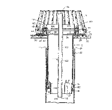
Reference is made first to Figure 2 which shows a vent tube member 100 in
accordance with the present invention which vent tube member 100 is
illustrated as used
in Figures 1 and 3 in the context of providing an improved roof drain insert
and an
improved roof drain assembly in accordance with the present invention. The
roof drain
assembly illustrated in Figures 1 and 3 to 9, otherwise than in respect of the
vent tube
member 100, is identical to that disclosed in U.S. patent 4,799,713 to Uglow)
issued
January 24, 1989 and, therefor, Figures 4 to 9 which do not show the vent tube
member
100 are prior art.
Figure 1 which shows a roof drain assembly in accordance with the present
invention comprising roof drain insert member 10 including vent tube member
100, clamp
ring member 12, straining basket 14, seal ring 16 and washer 18.
The assembly is shown in Figure 1 in the context of a roof generally indicated
20
supported by means not shown and below which a drain pipe 22 is located also
supported by
means not shown. A thin water impermeable sheeting 23 covers roof 20. The roof
drain
-4-
CA 02257777 1999-O1-06
insert member 10 is sealed to both sheeting 23 and drain pipe 22 and serves to
transfer
water collected on the roof to the drain pipe 22.
Drain insert member 10 has a cylindrical tube portion generally indicated 24
with
an upper opening 26 at its upper end and a lower opening 27 at its lower end.
Member 10
also has a thin, planar flange 28 extending radially outwardly about upper
opening 26.
The flange 28 is secured to the roof 20 by screws 30. Clamp ring member 12
overlies flange 28 and is secured to flange 28 clamping sheeting therebetween
by screw
members 60 extending through socket forming members 44 of the clamp ring
member 12 to
engage the post members 34 of the flange 28. The straining basket 14 is
removably secured
in a snap fit on a rim 64 of the clamp ring member 12.
The cylindrical tube portion 24 of the drain insert member 10 extends
downwardly
through the upper open end 114 of the drain pipe 22 coaxially into the drain
pipe 22.
The lower end of tube portion 24 is sealed to drain pipe 22. While this may be
accomplished in a number of ways, a preferred construction is shown in Figures
1 and 5 to 7
in accordance with the teaching of U.S. Patent 4,505,499 to Uglow et al,
issued March 19,
1985.
Tube portion 24 is recessed inwardly about lower opening 27 so as to provide
outwardly thereof an annular space 80 to receive about tube portion 24 annular
seal ring
16 and washer 18 in axially sliding relation. Washer 18 has three enlarged
radially
inwardly extending lugs 82 each carrying metal nuts 84 secured therein. Three
screws 86
extend from radial lugs 88 of tube portion 24 downward to engage nuts 84 and
draw
washer 18 upwardly so as to compress seal ring 16 preferably of compressible,
elastomeric (rubber) material. Ring 16 on being compressed is urged outwardly
into
sealing engagement with the inside wall 90 of drain pipe 22 as well as axially
into the
recessed, radially inwardly extending annular shoulder 92 of tube portion 24.
As shown,
annular space 80 is only of a radial inward extent equal to the thickness of
ring 16 except
at three places where it is enlarged under lugs 88 as at 94 to accommodate
lugs 82 of
washer 18. Lugs 88 present an upper flat surface which the head of screw 86
may
engage between reinforcing flanges 96. Screws 86 are accessible through upper
opening
26.
The vent tube member 100 comprises a hollow cylindrical tube 102 with an open
upper end 104 and an open lower end 106.
-5-
CA 02257777 1999-O1-06
The vent tube member 100 has two support arms 108 secured thereto carrying L-
shaped washer-like members 110. As best seen in Figure 1, the vent tube member
100 is
secured to the roof drain insert member by the support arms 108 spanning the
opening 26
and having its members 110 secured by screw members 60 in opposing socket
forming
members 44 and post members 34. As seen, the tube 102 is located coaxially
within both
the drain pipe 22 and the tube portion 24 of the drain insert member 10. The
upper end 104
of tube 102 is located at a height above the opening 26 in the drain insert
member 10. The
lower end 106 of tube 102 is located below the lower end 27 of the tube
portion 24.
The assembly as shown in Figure 1 provides, in effect, a primary flow
passageway
which extends from the opening 26 of the insert member 10 through the tube
portion 24 and
out of the tube portion into the drain pipe 22. In this regard, the primary
passageway may be
seen to have segments of different horizontal cross-sectional area, namely, an
entrance
segment indicated as 116, a restriction segment indicated as 118 and an exit
segment
indicated as 120.
The tubular portion 24, in effect, provides an annular restriction within the
drain
pipe 22 such that the horizontal cross-sectional area of the tubular portion,
especially in the
restriction segment 118, is less than the horizontal cross-sectional area of
the drain pipe 22.
The cross-sectional area of the primary passageway abruptly increases on
moving
downwardly from the restriction segment 118 into the exit segment 120 as in
the manner of a
step increase at their juncture.
The enlarged cross-sectional area in the exit segment 120 immediately below
the
annular restriction formed by the insert member 10 provides a location where
under certain
flow conditions, air may become entrapped in the primary passageway by water
flowing
down the drain. The tube 102 provides a secondary passageway 122 providing
communication through the tube 102 between the upper end 104 and lower end
106. The
upper end 104 is disposed above the upper opening 26 to the primary
passageway, such
that under conditions of relatively high water flow, the upper end 104 is
above the height of
water which may back up on the roof. The lower end 106 is disposed below the
restriction
segment 118 in the exit segment 120 but, preferably, proximate the juncture
between the
restriction segment 118 and exit segment 120 to assist in providing
communication to the exit
segment 120 proximate where the primary passageway widens into the exit
segment 120.
Operation of the drain assembly with the vent tube member 100 is not fully
understood. At low water flow rates, the vent tube member 106 is not believed
to have any
-6-
CA 02257777 1999-O1-06
substantial effect on water flow as compared to an assembly without the vent
tube member.
As the water flow rate increases, conditions will be reached where air becomes
entrapped in
the exit segment 120 and/or the entry segment 116 as by being within the drain
pipe 22
below the insert member 10 when the higher water flow commenced or by reason
of being
entrapped in downward flowing water and released into the exit segment 120. In
a drain
assembly without the vent tube member, the entrapped air can cause increased
resistance
to water flow through the drain pipe. However, in a drain assembly with the
vent tube
member, the vent tube provides the second passageway to equalize and/or
relieve pressure
differentials between the ends of the tube 100 as, for example, to vent air
upwardly from the
exit segment 120 immediately below the insert member 10 or to permit air to be
drawn
downwardly through the vent tube. As rain on the roof may accumulate in a
heavy In and the
water level on the roof may rise with increased backlog, the vent tube can
readily assist in
equalizing pressures as by venting air while the upper end 104 is above the
water level. By
the time the water level may rise above the upper end 104 of the tube 102, the
air venting is
likely substantially complete so that with the water level above the upper end
104, most of
the air may be removed from-the system and water may fill and flow down both
the primary
passageway and the secondary passageway.
The preferred embodiment illustrated in Figure 1 roughly approximates an
assembly with a drain pipe 22 of an inside diameter of 3 inches for a cross-
sectional area of
about 7.1 sq. in.; an insert member 10 with a restriction segment 118 of a
diameter of about
2.5 inches for an area of about 4.9 sq. in.; an entrance segment diameter of
about 2.75
inches for an area of about 5.9 sq. in.; and a tube 100 of an external
diameter of about 1/2
inches and an internal diameter of about 3/8 inches for an internal cross-
sectional area of
about 0.11 sq. in. Preferably, the area of the secondary passageway is
substantially smaller
than that of the primary passageway. Preferably, the cross-sectional area of
the secondary
passageway is less than 10%, preferably, less than 5% of the cross-sectional
area of the
drain pipe 22.
Conventional roof drain pipes such as 22 most typically have an interior
diameter
in the range of about 3 to 6 inches. Typical roof drain inserts having annular
sealing rings
such as 10 may be expected to have diameters in their restriction segment of
at least about
one half inch less than the diameter of the drain pipe. For a 6 inch drain
pipe, this represents
about 23 % less cross-sectional area in the restriction segment than in the
exit segment and,
for a three inch drain pipe, this represents about 30% less cross-sectional
area in the
restriction segment than in the exit segment. The present invention is,
therefore, preferable
7-
CA 02257777 1999-O1-06
for use in drain assemblies in which the annular restriction represents at
least about a 15%
reduction in the cross-sectional area of the drain pipe 22, more preferably,
at least about a
23 % reduction.
In conventional drain pipes of about 6 inch to 3 inch diameters, vent tubes
having
various cross-sectional sizes can be used. Preferred vent tubes have an
internal diameter in
the range of 0.25 inches to 1 inch, more preferably, about 3/8" to 5I8". The
cross-sectional
area of the drain pipe 22 is preferably about 30 to 100 times the internal
cross-sectional area
of the vent tube.
Figures 1 to 3 show the vent tube 102 located coaxially centered within the
drain
insert member 10. This is not necessary. The vent tube 102 could be provided
at other
locations as, for example, adjacent one side wall of the drain insert member
10, possibly
secured by but one screw 60 at its top. The secondary passageway could be
provided
integrally in the side wall of the drain insert member and could be provided
inside and outside
or in part inside and in part outside of the side wall of the drain insert
member.
The upper end 104 of the vent tube 100 in the preferred embodiment shown is
located above the opening 26 by approximately between 20% to 100% of a
diameter of the
drain pipe 22 yet below the top of the straining basket 24.
The lower end 106 of the vent tube 100 is preferably located a distance below
the
end of the restriction segment 118 between about 20% to 100% of the diameter
of the drain
tube 22.
The preferred vent tube 100 is shown secured in place, namely, by support arms
108. Additional support and/or locating devices could be provided as near the
lower end 106
to keep the vent tube 100 in a desired location. It is preferred, however,
that any support
devices be minimized to not restrict water flow or flow of debris through the
drain.
Other features of the roof drain insert shown in Figures 4 to 9 are now
discussed in
more detail. Referring to Figure 4, flange 28 has circumferentially spaced,
counter-sunk
holes 30 therein, through which recessed head screws 32 extend to secure
flange 28 to roof
20 with a lower surface of flange 28 in locating abutment with an upper
surface of roof 20.
Flange 28 carries six post members 34 which extend upwardly beyond upper
surface 36 of flange 28. Each post member 34 is shown to be substantially
cylindrical and to
have a central aperture 38 which extends downwardly into post member 34.
Central
_g_
CA 02257777 1999-O1-06
aperture 38 does not extend entirely through flange 28 but rather terminates
as a blind end
40.
Clamp ring member 12 overlies flange 28 such that a central opening 42 through
ring member 12 provides access to tubular portion 24 via upper opening 26.
Substantial
portions of ring member 12 are relatively thin and planar.
Six socket forming members 44 are provided on ring member 12 each rising above
the upper surface 46 of ring member 12. Socket forming members 44 each define
a socket
recess 48 therein. Recess 48 has a lower opening 50 in lower surface 52 of
ring member
12. Socket forming members 44 constitute a generally cylindrical upstanding
wall 58 which
at its upper end preferably extends radially inwardly to provide an inwardly
extending flange
56 at the top of member 44. An entrance aperture extends downwardly through
the top of
each member 44 into socket recess 48.
Socket forming members 44 are complementarily located having regard to the
location of post members 34 so that each socket recess 48 may receive a post
member 34
therein.
Screw member 60 extends downwardly through the top of socket forming member
44 via the entrance aperture and into central aperture 38 of a post member 34
received
inside socket recess 48. Screw member 60 engages post member 34 to urge ring
member
12 onto flange 28. Preferably, screw member 60 carries a washer 62 to
distribute loads onto
socket forming member 44.
With sheeting 23 located between flange 28 and ring member 12
circumferentially
about flange 38, sheeting 23 can be clamped between ring member 12 and flange
28 to form
a seal entirely about the periphery of the drain assembly.
Although not necessary, screws 32 fastening flange 28 to roof 20 may be
located
under sheeting 23 and flush with the upper surface of flange 28.
Ring member 12 preferably is provided at its outer edge with a segmented rim
64
which extends vertically upwardly (axially) above upper surface 46 of ring
member 12 to
where rim 64 has an enlarged radially outwardly extending flange-like lip 66.
Rim 64 is
shown as a plurality of circumferentially spaced segments, each designated 64
separated by
vertical spaces or cut-out portions 70 extending downwardly to the height of
upper surface 46
of ring member 12 as best seen in Figure 4. When used in securing roof
sheeting 23,
_g_
CA 02257777 1999-O1-06
spaces 70 permit water to pass through rim 64 when the water rises merely to
the height of
upper surface 46 of the ring member.
While Figures 1, 4 and 8 show use of a drain assembly in its preferred use
with
roof sheeting 23, the drain assembly can also be used with an asphalt type
roof sealing
system as shown in Figure 9 in which a layer 72 of tar, asphalt or other
sealant, preferably
covered by gravel 74, may be poured directly over roof 20. In this case, ring
member 12 is
urged directly onto flange 28. Segmented rim 64 serves to help the asphalt or
tar 72 and
gravel 74 from entering the drain.
In order to securely grip sheeting 23, as seen in Figure 4, the lower surface
52 of
ring member 12 may have one or more downwardly extending angular ridges 98.
Preferably,
complementary located and sized grooves 99 may be provided in the upper
surface 36 of
flange 28, to assist in gripping sheet 23 and also, as shown in Figure 9 when
no sheet is
between the ring member 12 and flange 28, to accommodate ridges 98.
The drain assembly preferably has a staining basket 14 which prevents leaves,
twigs, paper and the like from entering and clogging the drain. Basket 14 is
shown to have a
lower peripheral edge 75 with a downwardly extending inner projection 76 to
closely contact
the radially inside surface of rim 64. Preferably, three catch members 77 are
provided on
basket 14 as seen in Figure 1. Catch members 77 engage under lip 66 to
securely retain
basket 14 onto ring member 12. With basket 14 having some resiliency, basket
14 may be
snapped on and off of lip 66.
Preferably, each of drain insert member 10, ring clamp member 12, straining
basket 14 and washer 18 may be moulded from plastic as by injection moulding.
The
particular configuration of the post members permits moulding of the drain
insert member
with a two piece mould with the tube portion tapering a minor, insignificant
amount
downwardly. One piece of the mould may provide the upper and inside surfaces
while the
other piece of the mould may provide the lower and outer surfaces of the tube
portion 24.
Providing the post members and socket forming members to be upstanding about
the upper surfaces of the flange and the clamp ring member is advantageous
where asphalt,
tar or other sealing materials are to be applied and frequently are to be
slopped onto a drain,
making location of screw holes difficult.
-10-
CA 02257777 1999-O1-06
With the post members having a blind end and effectively sealing the thread
portion of screw member 60 therein, corrosion of the screw member can more
easily be
withdrawn after the passing of time, if necessary.
In the preferred embodiment shown, the post members and socket forming
members have been shown to be cylindrical. It is to be appreciated that many
other
complementary shapes could also be used.
While the invention has been described with reference to preferred
embodiments,
the invention is not so limited. Many variations and modifications will now
occur to those
skilled in the art. For a definition of the invention, reference is made to
the appended claims.
-11-