Note: Descriptions are shown in the official language in which they were submitted.
CA 02258072 1998-12-10
WO 97/47248 PCT/US97/03559-
-1-
REUSABLE CANNULA WITH DISPOSABLE SEAL
Field of the Invention
The invention pertains to a disposable seal
assembly for use with a reusable cannula. The seal
assembly is designed to be removably snapped onto the
cannula for use during a single medical procedure
(such as a laparoscopic procedure) and the cannula is
designed for multiple use (each time with a different
seal assembly) during multiple medical procedures.
The seal assembly includes at least one instrument
seal (for preventing fluid flow out from the cannula
when a medical instrument is inserted through the
seal assembly), and preferably also a flapper valve
fluid seal (for sealing the cannula when no medical
instrument is inserted through the seal assembly).
Background of the Invention
Many medical procedures require use of a
cannula, through which one or more medical
instruments are inserted into a patient and then
removed from the patient.
For example, in a variety of laparoscopic
medical procedures (including laparoscopic hernia
repair), a cannula is positioned with its distal end
inside the patient and its proximal end outside the
patient, and one or more medical instruments are
inserted through the cannula into the patient. For
example, each of a sequence of instruments (including
an endoscope) can be inserted through the cannula
into the patient and then withdrawn (in the opposite
direction) out from the patient and cannula.
During many such procedures, it is necessary to
maintain an insufflated working space within the
patient (by maintaining insufflating gas at
CA 02258072 1998-12-10
WO 97/47248 PCT/US97/03559'
-2-
sufficiently high pressure in the working space)
while the distal end of the cannula extends into the
working space. For use during these procedures, the
cannula must be provided with a seal or seals for
preventing undesired fluid escape from within the
patient out through the cannula. The term "fluid" is
used herein to denote either a gas or a liquid. One
such seal (denoted herein as a "fluid" seal) prevents
fluid escape from the cannula when no instrument
occupies the cannula's channel. A fluid seal is
implemented as a flapper valve, duckbill valve, or
other valve, which is biased in a closed position at
times when no instrument occupies the cannula's
channel to provide a fluid seal preventing fluid flow
through the channel at such times. When the distal
end of an instrument is inserted into the channel and
the instrument is advanced through the channel toward
the patient, the instrument opens the fluid seal
(e. g., by displacing the flexible slits of a duckbill
valve or displacing the trap door of a flapper
valve).
Typically also, an additional seal (sometimes
denoted herein as an "instrument seal") is employed
in a cannula to provide a fluid seal around the
instrument's outer periphery, to prevent fluid flow
through the space between the instrument and the wall
of the channel.
Typical prior art cannulae have had a
complicated design with a built-in fluid seal and
usually also an instrument seal. Such cannulae were
expensive to manufacture. They were also difficult
to clean after use, since contaminants often coated
or became lodged in those small valve and seal parts
which were in fluid communication with the cannula
channel or the instrument inserted through the
CA 02258072 1998-12-10
WO 97/47248 PCT/US97/03559 -
-3-
cannula. Often, the design of such a cannula was
further complicated by the need for a mechanical
linkage for manually controlling the flapper valve
(e.g., to enable sufficient manual force to be
applied on the linkage by a user to open the flapper
valve in cases where sufficient force could not be
exerted directly on the valve by an instrument
without damaging the valve, another component of the
cannula, or the instrument, or to enable the flapper
valve to be opened for cleaning or the like).
For example, U.S. Patent 5,104,383, issued April
14, 1992, describes a cannula having a built-in
flapper valve, and a removable "adaptor seal" which
provides an instrument seal for an instrument of a
first diameter. The adaptor seal can be removed and
replaced by another adaptor seal which provides an
instrument seal for an instrument of a second
diameter.
For another example, U.S. Patent 5,385,560,
issued January 31, 1995, describes a cannula having a
built-in flapper valve, and a built-in instrument
seal for an instrument having a relatively large
diameter. A "reducer" member snaps on the end of the
cannula, to provide an instrument seal for an
instrument (having a relatively small diameter) which
may be inserted through the cannula.
For another example, U.S. Patent 5,290,245,
issued March 1, 1994, describes a cannula having
several threaded portions which are assembled by
being screwed together. The cannula includes a
flapper valve mounted on one of the portions and an
instrument seal mounted on another of the portions.
It has been proposed to design a cannula to have
a distal portion (for insertion in a patient), and a
proximal portion which is removably attachable to the
CA 02258072 1998-12-10
WO 97/47248 PCT/US97/03559-
-4-
first portion and which includes a fluid seal. For
example, U.S. Patent 5,460,615, issued October 24,
1995 to Karl Storz, discloses (with reference to
Figures 4-7) a cannula having a distal portion (with
a trocar sleeve and a valve housing) and a proximal
portion (with a flapper valve, a first instrument
seal, and a second instrument seal attached by a
tether to the first instrument seal). A bayonet
closure is provided for removably attaching the
proximal portion to the distal portion. However, the
proximal portion has a complicated structure, it
would be expensive to manufacture, and it is not
intended to be used once and then discarded.
It had not been known until the present
invention how to design a cannula assembly with a
simple reusable cannula, and a simple disposable seal
(including both a flapper valve fluid seal and at
least one instrument seal) which can be snapped onto
the cannula and then readily removed after use.
Summary of the Invention
In a class of preferred embodiments, the
invention is a disposable seal assembly for use with
a reusable cannula, where the seal assembly is
designed for use with the cannula during a single
medical procedure (such as a laparoscopic procedure)
and the cannula is designed for multiple uses (each
time with a different seal assembly) during a number
of medical procedures. A channel extends through the
seal assembly, and the seal assembly includes both a
flapper valve fluid seal (for sealing the cannula
when no medical instrument is inserted through the
seal assembly) and at least one instrument seal (for
sealing the cannula when a medical instrument is
inserted through the seal assembly). Preferably, the
CA 02258072 1998-12-10
WO 97/47248 PCT/US97/03559
-5-
seal assembly has a body with a flange which can be
snapped onto the cannula (so that the flange fits in
a groove of the cannula) before use, and can be
readily removed from the cannula after use. The seal
assembly is preferably molded from an elastomeric
material (e.g., rubber), except for the trap door of
its flapper valve. In preferred embodiments, the
trap door is molded from a rigid material (e.g., a
rigid plastic), and is mounted to the elastomeric
portion of the assembly. This simple design makes the
assembly inexpensive to manufacture and thus
disposable. Alternatively, the entire seal assembly
(including a trap door portion thereof) can be molded
from an elastomeric material (e. g., rubber).
Preferably, the trap door is mounted on an over-
centered door hinge designed to reduce the drag force
exerted by the opened door on an instrument, as the
instrument translates past (and displaces) the door.
The door preferably has slits extending through it,
and the over-centered hinge preferably includes
appropriately shaped extensions of the seal
assembly's elastomeric portion which are inserted
through the slots to mount the door. Each extension
typically has a barb (for retaining the door after
the end portion of the extension and the barb have
been inserted through a slot through the door), and
thus the extensions are sometimes denoted herein as
"barbed portions."
Preferably, the trap door is mechanically joined
to (e.g., molded with) flexible extensions of the
seal assembly's elastomeric portion so that, if the
door becomes improperly positioned, the extensions
exert restoring force on the door thereby
repositioning the door properly. Alternatively,
direct manual force exerted by a user on the door
CA 02258072 1998-12-10
WO 97/47248 PCT/US97/03559-
-6-
together with restoring force exerted by the
extensions on the door, is sufficient to reposition
the door if it becomes improperly positioned.
Preferably, the channel has a first radius at a
first end of the seal assembly's body, and there is a
bumper along the channel (away from the first end}
having a smaller radius (with respect to the central
longitudinal axis of the channel) than the first
radius. The bumper, which is preferably a molded
portion of the seal assembly's body, functions to
limit lateral movement of an instrument extending
through the channel. Preferably, when the seal
assembly is mounted to the cannula, the bumper is
positioned so that the cannula bears at least part of
the load exerted on the bumper by the instrument (to
limit undesired deformation of the elastomeric
portion of the seal assembly).
In preferred embodiments, the seal assembly
includes a main portion and an adaptor portion. The
flapper valve is mounted to the main portion, the
main portion includes an instrument seal for use with
a relatively large diameter instrument, and the
adaptor portion includes an instrument seal for use
with a smaller diameter instrument, and preferably
also a bumper. Preferably the main and adaptor
portions are connected by a tether portion, and all
three portions (including the bumper of the adaptor
portion) are a single molded piece of elastomeric
material.
In other embodiments, the invention is a seal
assembly including at least one double instrument
seal, comprising a sacrificial flange and a second
sealing flange (for sealing the cannula when a
medical instrument is inserted through the seal
assembly even when the sacrificial flange has been
CA 02258072 2005-06-27
75416-6
cut during insertion of the instrument). In preferred
embodiments, the seal assembly includes a flapper valve
fluid seal as well as such a double instrument seal.
In other embodiments, the invention is a cannula
system including a reusable cannula, and a disposable seal
assembly (of any of the described types) which can be
snapped onto the cannula before use and readily removed
after use. The cannula of such a system preferably includes
no fluid seal or instrument seal, and thus is easy to clean
after use. In other embodiments, the invention is a method
for using such a cannula system.
In accordance with one aspect the invention
provides a disposable seal assembly, including:a body
through which a channel extends, wherein the body includes a
flange shaped for removably attaching the body to a cannula;
a flexible extension protruding out from the body; a trap
door mounted to the flexible extension, such that the
flexible extension biases the door into a closed position
which seals the channel and the flexible extension can move
in response to displacement of the door from the closed
position by an instrument translating through the channel;
and at least one instrument seal which seals the channel
when the instrument is positioned in the channel, wherein
the body, the flange, the flexible extension, and each said
instrument seal are portions of a single piece of molded
elastomeric material, the flexible extension comprises two
portions of said piece of molded elastomeric material, and
the door is mechanically joined to said two portions.
According to another aspect the invention provides
a disposable seal assembly, including: a body through which
a channel extends, wherein the body includes a flange shaped
for removably attaching the body to a cannula; a flexible
CA 02258072 2005-06-27
75416-6
-7a-
extension protruding out from the body; a trap door mounted
to the flexible extension, such that th.e flexible extension
biases the door into a closed position which seals the
channel and the flexible extension can move in response to
displacement of the door from the closed position by an
instrument translating through the channel; and at least one
instrument seal which seals the channel when the instrument
is positioned in the channel, wherein the body, the flange,
the flexible extension, and each said instrument seal are
portions of a single piece of molded elastomeric material,
the flexible extension comprises two barbed portions of said
piece of molded elastomeric material, the door has two slots
extending therethrough, and each of the barbed portions
extends through one of the slots.
According to another aspect the invention provides
a disposable seal assembly, including: a body through which
a channel extends, wherein the body includes a flange shaped
for removably attaching the body to a cannula, wherein the
channel has a first radius at a first erad of the body; a
flexible extension protruding out from the body; a trap door
mounted to the flexible extension, such that the flexible
extension biases the door into a closed position which seals
the channel and the flexible extension can move in response
to displacement of the door from the closed position by an
instrument translating through the channel; at least one
instrument seal which seals the channel when the instrument
is positioned in the channel; and a bumper positioned along
the channel away from the first end, said bumper having a
second radius smaller than the first radius, so that the
bumper limits lateral movement of the instrument when said
instrument is positioned in the channel.
According to another aspect the invention provides
a disposable~seal assembly, including: a body through which
CA 02258072 2005-06-27
75416-6
-7b-
a channel extends, wherein the body includes a flange shaped
for removably attaching the body to a cannula, wherein the
channel has a first diameter; a flexible extension
protruding out from the body; a trap door mounted to the
flexible extension, such that the flexible extension biases
the door into a closed position which seals the channel and
the flexible extension can move in response to displacement
of the door from the closed position by an instrument
translating through the channel; and at least one instrument
seal which seals the channel when the instrument is
positioned in the channel, wherein the at least one
instrument seal includes: a sacrificial flange positioned at
a first location along the channel; and a sealing flange
positioned at a second location along the channel, wherein
the sealing flange provides a seal around the instrument
when said instrument is positioned in the channel.
According to another aspect the invention provides
a disposable seal assembly, including: a body through which
a channel extends, wherein the body includes a flange shaped
for removably attaching the body to a cannula, wherein the
channel has a first diameter; a flexible extension
protruding out from the body; a trap door mounted to the
flexible extension, such that the flexible extension biases
the door into a closed position which seals the channel and
the flexible extension can move in response to displacement
of the door from the closed position by an instrument
translating through the channel; at least one instrument
seal which seals the channel when the instrument is
positioned in the channel, said at least one instrument seal
providing a seal around the instrument when said instrument
is positioned in the channel; and an adaptor connected to
the body, the adaptor including: an adaptor body through
which an adaptor channel extends; a tether connected between
CA 02258072 2005-06-27
75416-6
-7c-
the body and the adaptor body; an adaptor flange shaped for
removably attaching the adaptor body to the body with the
adaptor channel aligned with the channel; and an adaptor
instrument seal which provides a seal around a small
diameter instrument when said small diameter instrument is
positioned in the adaptor channel, where the small diameter
instrument has a second diameter and the second diameter is
smaller than the first diameter.
According to another aspect the invention provides
a disposable seal assembly, including: a body through which
a channel extends, wherein the body includes a flange shaped
for removably attaching the body to a cannula, and the body
has a mounting portion; a trap door mounted to the mounting
portion of the body such that the mounting portion biases
the door into a closed position which seals the channel and
the mounting portion can move in response to displacement of
the door from the closed position by an instrument
translating through the channel; and at Least one instrument
seal which seals the channel when the instrument is
positioned in the channel, wherein the body including the
mounting portion, the flange, and each said instrument seal
are portions of a single piece of molded elastomeric
material, wherein the mounting portion comprises two barbed
portions of said piece of molded elastomeric material, the
door has two slots extending therethrough, and each of the
barbed portions extends through one of the slots.
According to another aspect the invention provides
a disposable seal assembly, including: a body through which
a channel extends; a sacrificial flange positioned at a
first location along the channel; a sealing flange
positioned at a second location along the channel, wherein
at least one of the sacrificial flange a:nd the sealing
flange provides a seal around an instrument when said
CA 02258072 2005-06-27
75416-6
-7d-
instrument is positioned in the channel, wherein the
sacrificial flange is shaped so that in response to
displacement of a portion of the sacrificial flange by the
instrument while the instrument is inserted through the
channel, a displaced portion of the sacrificial flange folds
toward the sealing flange, thereby displacing the sealing
flange to prevent said sealing flange from being cut by the
instrument as said instrument continues translating through
the channel; and a mounting flange protruding from the body,
wherein the mounting flange is shaped for removably snapping
the body onto a cannula, wherein the body, the sacrificial
flange, the sealing flange, and the mounting flange are
portions of a single piece of molded elastomeric material.
According to another aspect the invention provides
an adaptor seal for an elastomeric seal assembly, including:
a body through which a channel extends; a sacrificial flange
positioned at a first location along the channel; a sealing
flange positioned at a second location along the channel,
wherein at least one of the sacrificial flange and the
sealing flange provides a seal around an instrument when
said instrument is positioned in the channel, wherein the
sacrificial flange is shaped so that in response to
displacement of a portion of the sacrificial flange by the
instrument while the instrument is inserted through the
channel, a displaced portion of the sacrificial flange folds
toward the sealing flange, thereby displacing the sealing
flange to prevent said sealing flange from being cut by the
instrument as said instrument continues i~ranslating through
the channel; and a mounting flange protruding from the body,
wherein the mounting flange is shaped for removably mounting
the body to the elastomeric seal assembly.
According to another aspect the invention provides
a cannula system, comprising: a reusable cannula which has a
CA 02258072 2006-02-28
75416-6
-7e-
first end but includes neither a fluid seal nor an
instrument seal; and a disposable seal assembly, wherein the
disposable seal assembly comprises: a body through which a
channel extends, said body including a flange removably
attached to the first end of the cannula; a flexible
extension which protrudes out from the body; a trap door
mechanically joined to the flexible extension, so that the
flexible extension biases the door into a closed position
which seals the channel, and the flexible extension moves in
response to displacement of the door from the closed
position by an instrument translating through the channel;
and at least one instrument seal which seals the channel
when the instrument is positioned in the channel, wherein
the cannula has a groove at said first end, and the flange
is removably snapped into said groove.
According to another aspect the invention provides
a cannula system, comprising: a reusable cannula which has a
first end but includes neither a fluid seal nor an
instrument seal; and a disposable seal assembly, wherein the
disposable seal assembly comprises: a body through which a
channel extends, said body including a flange removably
attached to the first end of the cannula; a flexible
extension which protrudes out from the body; a trap door
mechanically joined to the flexible extension, so that the
flexible extension biases the door into a closed position
which seals the channel, and the flexible extension moves in
response to displacement of the door from the closed
position by an instrument translating through the channel;
and at least one instrument seal which seals the channel
when the instrument is positioned in the channel, wherein
the body, the flange, the flexible extension, and each said
instrument seal are portions of a single piece of molded
elastomeric material, the flexible extension comprises two
CA 02258072 2005-06-27
75416-6
_7f_
portions of said piece of molded elastomeric material, the
door has two slots extending therethrough, and each of the
two portions extends through one of the slots.
According to another aspect the invention provides
a cannula system, comprising: a reusable cannula which has a
first end but includes neither a fluid seal nor an
instrument seal; and a disposable seal assembly, wherein the
disposable seal assembly comprises: a body through which a
channel extends, said body including a flange removably
attached to the first end of the cannula, wherein the
channel has a first radius at a first end of the body; a
flexible extension which protrudes out from the body; a trap
door mechanically joined to the flexible extension, so that
the flexible extension biases the door into a closed
position which seals the channel, and t:he flexible extension
moves in response to displacement of the door from the
closed position by an instrument translating through the
channel; and at least one instrument seal which seals the
channel when the instrument is positioned in the channel;
and a bumper positioned along the channel away from the
first end of the body, said bumper having a second radius
smaller than the first radius, so that i~he bumper limits
lateral movement of the instrument when said instrument is
positioned in the channel.
According to another aspect the invention provides
a cannula system, comprising: a reusable cannula which has a
first end but includes neither a fluid seal nor an
instrument seal; and a disposable seal assembly, wherein the
disposable seal assembly comprises: a body through which a
channel extends, said body including a flange removably
attached to the first end of the cannula, wherein the
channel has a first diameter; a flexible extension which
protrudes out from the body; a trap door mechanically joined
CA 02258072 2006-02-28
75416-6
_7g_
to the flexible extension, so that the flexible extension
biases the door into a closed position which seals the
channel, and the flexible extension moves in response to
displacement of the door from the closed position by an
instrument translating through the channel; at least one
instrument seal which seals the channel when the instrument
is positioned in the channel, the at least one instrument
seal providing a seal around the instrument when said
instrument is positioned in the channel; and an adaptor
connected to the body, wherein the adaptor includes: an
adaptor body through which an adaptor channel extends; a
tether connected between the adaptor body and a body; an
adaptor flange shaped for removably attaching the adaptor
body to the body with the adaptor channel aligned with the
channel; and an adaptor instrument seal which provides a
seal around a small diameter instrument when said small
diameter instrument is positioned in the adaptor channel,
where the small diameter instrument has a second diameter
and the second diameter is smaller then the first diameter.
According to another aspect the invention provides
a method for using a cannula system, said system including a
reusable cannula and a disposable seal assembly having a
flange shaped for removable attachment to an end of the
cannula, wherein the seal assembly includes a mounting
portion made of elastomeric material and a trap door mounted
to the mounting portion, wherein the mounting portion has a
first portion, the second channel has a longitudinal axis,
the door has a main portion for sealing the second channel,
an end portion about which the door pivots when displaced by
the instrument, and an intermediate portion attached to the
first portion of the mounting portion, wherein the end
portion and the first portion are separated by a first
distance perpendicular to the longitudinal axis when the door
CA 02258072 2006-02-28
75416-6
-7h-
is in the closed position, and wherein the cannula has a
first channel therethrough, and the seal assembly has a
second channel therethrough, said method including the steps
of: (a) assembling the system by snapping the flange of the
seal assembly into a groove of the cannula at said end of the
cannula, so that the first channel is aligned with the second
channel and the door is biased by the mounting portion into a
closed position which seals the first channel; (b) advancing
an instrument in a first direction through the second
channel, thereby displacing the door from the closed position
to an open position and bending and stretching the mounting
portion thereby causing the end portion and the first portion
to be separated by a second distance perpendicular to the
longitudinal axis when the door is in the open position,
where the second distance is less than the first distance;
and (c) withdrawing the instrument from the second channel in
a second direction opposite the first direction, thus
allowing the mounting portion to relax and thereby to return
the door to the closed position.
Brief Description of the Drawings
Figure 1 is a side elevational view of a
disposable seal and four reusable cannulae (each cannula
usable with the seal) according to a preferred embodiment of
the invention.
Figure 2 is a side cross-sectional view of
disposable seal 2 of Fig. 1, in a configuration in which
adaptor portion 20 has been snapped onto body portion 14.
Figure 3 is a top elevational view of trap door 16
of disposable seal 2 of Fig. 1.
Figure 4 is a side elevational view (partially cut
away) of trap door 16 of disposable seal 2 of Fig. 1.
CA 02258072 2006-02-28
75416-6
-7i-
Figure 5 is a top view (partially cut away to show
the location of one of barbed portions 18) of disposable
seal 2 of Fig. 1 (without trap door 16).
Figure 6 is a bottom view of disposable seal 2 of
Fig. 1 (without trap door 16).
Figure 7 is a side cross-sectional view of
disposable seal 2 of Fig. 1.
CA 02258072 1998-12-10
WO 97J47248 PCT/CTS97J03559'
_g_
Figure 8 is an enlarged view of the portion of
Fig. 1 labeled "Detail A."
Figure 9 is an enlarged view of the portion of
Fig. 1 labeled "Detail B."
Figure 10 is a side cross-sectional view of an
instrument seal designed in accordance with an
alternative embodiment of the invention.
Figure 11 is an enlarged view of a portion of
the Fig. 10 apparatus, with medical instrument 24
being translated toward the left therethrough.
Figure 12 is a side elevational view of a
reusable cannula according to a preferred embodiment
of the invention.
Figure 13 is a cross-sectional view of cannula
100 of Fig. 12 (taken along line Z-Z of Fig. 12),
with stopcock 9.
Figure 14 is an elevational view of reusable
cannula 8 (of Fig. 1), with seal 2 (of Fig. 1)
snapped onto the proximal end of the cannula, and a
stopcock 9 mounted to the cannula.
Figure 15 is a simplified side cross-sectional
view of an alternative embodiment of the inventive
disposable seal snapped onto the end of cannula 4 (of
Fig. 1), with a tissue specimen 200 being withdrawn
by instrument 24 through the cannula from a patient.
Figure 16 is a view of the Fig. 15 apparatus,
after specimen 200 has been further withdrawn from
the cannula.
Figure 17 is a view of the Fig. 16 apparatus,
after specimen 200 has been further withdrawn from
the cannula.
Figure 18 is a view of the Fig. 15 apparatus,
after specimen 200 has been completely withdrawn from
the cannula.
CA 02258072 1998-12-10
WO 97/47248 PCT/US97/03559-
_g_
Figure 19 is a view of the Fig. 18 apparatus,
after a user has pushed trap door 16 back into the
cannula.
Figure 20 is a side cross-sectional view of an
alternative embodiment of the inventive disposable
seal, which is molded as a single piece of
elastomeric material (including a trap door portion).
Figure 21 is a side view, partially elevational
and partially cross-sectional, of an alternative
embodiment of the inventive disposable seal, which is
molded as a single piece of elastomeric material.
Figure 22 is a side cross-sectional view of the
seal of Fig. 21, with adaptor portion 220 snapped
over main portion 240.
Figure 23 is a side cross-sectional view of an
alternative embodiment of the inventive seal, snapped
onto the end of cannula 4 (of Fig. 1).
Detailed Descrit~tion of the Preferred Embodiment
A preferred embodiment of the invention will be
described with reference to Figures 1-9 and 14.
Other embodiments will be described with reference to
Figs. 10-13 and 15-20.
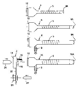
As shown in Fig. 1, seal assembly 2 is a
preferred embodiment of the inventive disposable
seal, and each of cannula 4, cannula 6, cannula 8,
and cannula 10 is an embodiment of the inventive
reusable cannula. Each of cannulae 4, 6, 8, and 10
has a distal end (end 4A, 6A, 8A, and 10A,
respectively) which is inserted within a patient
during use, and a proximal end opposite the distal
end. Each cannula has a central longitudinal channel
extending through it, and any of a variety of
instruments (such as relatively small diameter
instrument 24' which can be an obturator or
CA 02258072 1998-12-10
-10-
endoscope) can be positioned in the channel while the
cannula is inserted into the patient (or after the
cannula has been inserted into the patient). The
outer wall of each cannula (each cannula is
preferably made of a rigid material such as metal or
rigid plastic) has a grip portion 5. Preferably,
grip portion 5 produced by scoring a pattern (e.g., a
spiral pattern as shown in Fig. 1) into the outer
metal surface of the cannula. Alternative
embodiments of the cannula have no grip portion, and
instead the outer wall of each is smooth.
The proximal end of each cannula is
identically shaped and sized, so that seal assembly 2
can be snapped onto any of them. More specifically,
the proximal end of each of cannuiae 4, 6, 8, and 10
is generally cylindrical, and has an identical
anr_ular groove 12 around it. A flange portion
(flange 17, shown in Fig. 2 but not in Fig. 1) c~
body portion 14 of seal assembly 2 can be snapped
into groove 12 to removably attach seal assembly 2
onto any of ~.he cannulae. Preferably, body 14 has a
thin annular portion 14a (shown in Fig. 2) between
flange 17 and the main portion of body 14. The thin
porti on 14a which has a thickness o= 0 . 03 -:~c:res i:~
one embodiment ) f>?ncti pnc as a bel l v~.~c al 1 p,,l~n=
flange 17 to flex relative to the main portion of
body 14, so that assembly 2 can be manipulated by a
user without removing flange 17 from groove 12.
Figure 14 is an elevational view of cannula 8,
with body portion 14 of assembly 2 snapped onto the
proximal end of cannula 8, and adaptor portion 20 of
seal 2 connected to body portion by tether 22.
As shown in both Fig. 1 and Fig. 14, stopcock 9
is mounted to an orifice (not shown in Fig. 1 or 14,
but identical to orifice 101 shown in Figs. 12 and
AMENDED SHEET
CA 02258072 2005-06-27
75416-6
-11-
13) which extends through cannula ~. A source of
insufflation gas can be connected to stopcock 9 at
desired times during a medical procedure, and
stopcock 9 can be opened (to allow gas to flow
through the orifice into or out from cannula 8) or
closed tto seal the orifice). Fig. 1 shows an
identical stopcock 9 mounted to eannula 10. Some
embodiments of the inventive reusable cannula have an
orifice to which a stopcock can be mounted, while
others (e. g., cannula 4) do not have such an orifice.
Preferably, seal 2 is molded from elastic
material (such as medical grade silicon rubber or
another medical grade elastomer), except for its
rigid trap door 16 (which can be molded from hard
plastic such as polycarbonate material). Thue, seal
has a simple design consisting of two components
only. In alternative embodiments, the trap door is
made of non-rigid material. In some such alternative
embodiments, to be described below with reference to
Fig. 20, the inventive seal is molded as a single
piece of elastomeric material (including an
elastomeric trap door portion). Cannulae 4, 6, 8, and
10 are preferably made of rigid such as stainleas-
steel for another metal) or rigid plastic.
Two flexible extension portions 18 protrude out
from body portion 14 of seal 2, and trap door 16 is
mounted on members 18. Preferably, each extension
portion 18 has a barb 18a for retaining~the door
against body portion 14 after the extension portion's
head (which preferably has a genE~aliy triangular
cross-section) and the barb have been inserted
through a slot through the door, and each extension
portion 18 also has a flexible shaft, connecting the
head to body portion 14. Thus, eac~u extension
portion 18 will sometimes be denoted herein as a
CA 02258072 2005-06-27
75416-6
-12-
"barbed portion", although it is contemplated that
flexible extensions having other shapes can be used
in alternative embodiments of the invention.
Hody portion 14 has a trap door seat gortion
(flange 31 shown in Fig. 2 but not in Fig. 11 which
surrounds the distal end of the central channel 15
(shown in Figs. 5 and 6) which extends through body
portion l4. Central channel 15 extends along central
longitudinal axis Z of seal 2 (shown in Fig. 2), and
preferably has rotational symmetry about axis Z.
Trap door 16 is biased by barbed portions 18 so
than it normally rests in a closed position against
the trap door seat, so that the closed trap door 16
prevents fluid from flowing througra central channel
15. Trap door 16, barbed portions 18, and the trap
door seat portion comprise a flapper valve, which
functions as follows. Barbed portions 38 are
flexible so that when seal 2 has been snapped onto a
cannula and an instrument te.g., relatively large
diameter instrument 24 of Fig. 1) is. inserted through
the central channel through body portion 14 (and
through the trap door seat and d~~o the channel
extending through the cannula), the instrument
displaces trap door 16 away from the trap door seat
(thereby bending barbed portions 18) and continues
into the cannula's channel (until the distal end of
the instrument passes entirely through the channel
and out the distal end of the cannula).. Then, when
the instrument is withdrawn from the cannula and seal
3n 2, barbed portions 18 relax, thus urging trap door 16
back into its normal position preventing fluid flow
past the trap door seat.
Preferably also, body 14 includes an instrument
seal portion tflanges 31 and 32, to be described
below) which prevents fluid flow past an instrument
CA 02258072 1998-12-10
WO 97/47248 PCT/US97/fl3559'
-13-
which has been inserted through seal 2. Typically,
such instrument seal portion is a simple flange (or
double flange of a type to be described below) which
extends into a central channel through seal 2.
Because such a flange (or double flange) has a fixed
diameter, it will not provide a good seal around
instruments having diameter less than a particular
value. Thus, adaptor portion 20 of seal 2 is
provided, so that adaptor portion 20 (attached to
body portion 14 by flexible tether 22) can be snapped
onto body portion 14 to adapt the seal for use with a
smaller diameter instrument. Adaptor 20 has an
instrument seal portion which can be a simple flange
(e.g., flange 38 shown in Figs. 5, 6, and 9) or a
double flange (including a sacrificial flange and a
seal flange) which extends into a central channel
through adaptor 20, for providing a good seal around
instruments having a range of relatively small
diameters. For example, when seal assembly 2 is
snapped onto the end of large diameter cannula 10,
relatively large diameter instrument 24 can be
inserted through body 14, and the instrument seal
within body 14 provides a good fluid seal around
instrument 24. If the user desires to insert an
instrument having substantially smaller diameter than
instrument 24 (e. g., relatively small diameter
instrument 24') into cannula 10, the user snaps
adaptor 20 onto body 14 (so that the central channels
through body 14 and adaptor 20 are aligned) and then
inserts the relatively small diameter instrument
through adaptor 20. When the relatively small
diameter instrument (e.g., instrument 24') is so
inserted through adaptor 20 (and body 14) into
cannula 10, the instrument seal within adaptor 20
provides a good fluid seal around the relatively
CA 02258072 1998-12-10
WO 97/47248 PCT/US97/03559-
-14-
small diameter instrument, and the relatively small
diameter instrument displaces door 16 of the flapper
valve within body 14.
It is contemplated that any of a variety of
variations on disposable seal 2 can be used
interchangeably with any of the cannulae. Each such
variation is a disposable seal having at least one
instrument seal (useful with instruments having a
particular outer diameter or range of outer
diameters) and a flapper valve.
In one embodiment, each of short cannula 4 and
long cannula 6 has a channel of diameter slightly
greater than 5 mm (for use with an instrument of 5 mm y
diameter), cannula 8 has a channel of diameter
slightly greater than 10 mm (for use with an
instrument of 10 mm diameter), and cannula 10 has a
channel of diameter slightly greater than 12 mm (for
use with an instrument of 12 mm diameter). For use
with all such cannulae and instruments, adaptor
portion 20 of seal 2 can include an instrument seal
of a diameter which provides a seal around an
instrument of 5 mm diameter, and body portion of seal
2 can include an instrument seal of a diameter which
provides a seal around an instrument having any
diameter in the range from 10 mm to 12 mm.
With reference to Fig. 2, adaptor portion 20 of
seal 2 has a distal end surrounded by a circular
flange 33. Adaptor portion 20 can be snapped onto
body 14 by inserting its distal end into the central
channel through body 14 until flange 33 translates
past shoulder 14c of body 14 into groove 14d of body
14, as shown in Fig. 2. With flange 33 in this
position, shoulder 14c locks adaptor portion 20 in
place, preventing flange 33 from translating in the
proximal direction (toward the top of Fig. 2) until a
CA 02258072 1998-12-10
WO 97/47248 PCT/US97/0355g
-15-
user grips body 14 (to hold body 14 in a fixed
position) and exerts manual force (in the proximal
direction) on one side of adaptor 20, such as by
pulling up on flap 23 of adaptor 20.
Trap door 16 is mounted on barbed portions 18 of
body 14 (shown in Figs. 2, 6, 7, and 8). Trap door
16 has a generally hemispherical portion which rests
against flange 31 when the flapper valve is in its
closed position shown in Fig. 2. Trap door 16 also
has a flange 16B, and two slots 16A extend through
flange 16B (as shown in Figs. 3 and 4). Trap door 16
is mounted to body 14 by inserting one barbed portion
18 through each slot 16A until shoulder 18a (of each
barbed portion) passes through slot 16A, and spacer
portion 16D of door 16 abuts body 14. Thus, each
barbed portion 18 is slightly stretched by the force
exerted on shoulder 18a by door 16, and barbed
portions 18 in turn exert a biasing force on door 16
tending to keep door 16 in the closed position
against the trap door seat (as shown in Fig. 2). As
the hemispherical portion of door 16 is displaced
away from the trap door seat (by an instrument which
pushes the hemispherical portion as the instrument
translates through the central channel of body 14),
barbed portions 18 will bend and also stretch, thus
allowing door 16 and barbed portions 18 to pivot away
from the instrument (together as a unit about spacer
16D) .
The biasing torque exerted by barbed portions 18
on door 16 (tending to keep door 16 in the closed
position shown in Fig. 2) is T = 2PX, where P is the
preload force exerted (toward the top of Fig. 2) on
door 16 by each barbed portion 18, and X is the
distance {shown in Fig. 2) between the center of
spacer 16D and the central longitudinal axis of each
CA 02258072 1998-12-10
WO 97/47248 PCT/US97/03559-
-16-
barbed portion 18. Since X is greater than zero,
door 16 is said to be mounted on an "over-centered"
door hinge.
As door 16 is displaced (by an instrument) into
its open position, barbed portions 18 will bend and
stretch, and the distance between.spacer 16D and the
central axis of each barbed portion will be reduced
to a value X' (where X' is less than X) as spacer 16D
slides slightly to the left in Fig. 2). This effect
tends to reduce the torque on door 16. The torque
exerted by barbed portions 18 on door 16 (when door
16 is in its opened position) is T = 2P'X' + M, where
M is the moment due to the bending of barbed portions
18, and P' is the increased preload force exerted on
door 16 by each barbed portion 18 (P' is greater than
P since barbed portions 18 become stretched, that is
elongated, when door 16 is in its opened position).
Door 16 and barbed portions 18 are designed so that
no more than an acceptable maximum torque is exerted
on door 16 by barbed portions 18, regardless of the
angle by which door 16 is rotated (about its pivot
point) from its closed orientation (e.g., so that the
torque reduction caused by the reduced factor X'
cancels a sufficient amount of the torque increase
due to the parameters P' and M). If the torque
exerted on door 16 (by barbed portions 18) is so
controlled, the opened door 16 will exert no more
than an acceptable amount of drag force on any
instrument being translated through channel 15 into
(or out from) the cannula to which seal 2 is
connected.
More generally, the trap door of the inventive
seal is preferably mounted on an over-centered door
hinge, such that the change in torque applied by the
seal to the door relative to the change in the
CA 02258072 1998-12-10
WO 97/47248 PCT/US97/03559-
-17-
orientation angle of the door decreases with
increasing pivoting displacement of the door away
from its closed orientation (i.e., such that d2T/dA2
is negative, where T is the applied torque and A is
the door's orientation angle relative to the
orientation angle of the closed door).
Also to reduce the drag force exerted by the
opened door on the instrument displacing the door,
the door surface which engages the instrument should
be a smooth, hard surface (for reduced friction) .
In alternative embodiments of the invention,
only one barbed portion is used to attach the trap
door to the body of the inventive seal. In this case,
the trap door would have only a single slot, rather
than dual slots 16A as shown in Fig. 3. To ensure
stable positioning of the door, such a single barbed
portion would typically be wider than barbed portions
18 shown in Figs. 2 and 6-8, in the sense that it
would extend farther around the periphery of channel
15 than does either of barbed portions 18 (of Figs. 2
and 6-8).
Also, in alternative embodiments of the
inventive seal assembly, the trap door of the seal
assembly is attached to the seal assembly's flexible
extensions (which are not necessarily barbed or
arrow-shaped) other than by inserting the extensions
through slots in the trap door. For example, the
trap door could be attached to the extensions by glue
or another adhesive (in such cases, the trap door
need not have a slot extending through it), or the
extensions could have one or more slots extending
through them and the trap door could fit through such
slot or slots.
With reference to Fig. 2, we next discuss small
diameter portion 14b of body 14 of seal 2, which
CA 02258072 1998-12-10
WO 97/47248 PCT/US97/03559'
-18-
functions as a bumper to limit lateral motion of a
large diameter instrument which occupies the central
channel through seal 2 (when adaptor portion 20 has
been removed from its position shown in Fig. 2 within
body 14). The channel has a first diameter 2R (shown
in Fig. 2) and thus a first radius R at a first end
of body portion 14, and bumper 14b has a smaller
diameter 2R' (and thus a radius R', relative to the
central longitudinal axis Z of the channel, which is
smaller than the first radius R). Bumper 14b does
not extend as far radially into the central channel
as does flange 32 or 31 (so that it does not
interfere with the sealing function of flange 31).
Instead, bumper 14b functions to limit lateral
movement of any large diameter instrument which
extends through the channel (as does bumper ring 95
in the Fig. 11 embodiment described below).
Preferably, bumper 14b is located low enough
along the longitudinal axis of seal assembly 2 so
that it rests against the cannula (when assembly 2 is
snapped onto the end of the cannula), allowing loads
from an instrument on bumper 14b to be borne by the
inner wall of the cannula to which assembly 2 is
mounted. This preferred arrangement is in contrast
with that of the Fig. 15 embodiment (to be discussed
below) in which end portion 4a of the wall of cannula
4 (shown in Fig. 15) is below bumper 14b' along the
vertical axis of the channel (extending through seal
assembly 2' and cannula 4) with which instrument 24
is aligned, so that bumper 14b' of Fig. 15 does not
rest directly against the wall of cannula 4, and the
cannula does not directly bear an instrument load on
bumper 14b'.
Preferably, adaptor 20 also has an instrument
seal {flange 38, best shown in Fig. 9) and a bumper
CA 02258072 1998-12-10
WO 97/47248 PCT/US97/03559'
-19-
(bumper 20a, best shown in Fig. 9) for limiting
lateral movement of any relatively small diameter
instrument which extends through the central channel
through adaptor 20. In the preferred embodiment of
adaptor 20 shown in Figs. 5-9, circular flange 38
extends sufficiently far radially into the central
channel so that it provides a seal preventing fluid
flow between flange 38 and the outer periphery of a
relatively small diameter instrument which extends
l0 through the central channel. Bumper portion 20a of
adaptor 20 does not extend as far radially into the
central channel as does flange 38 (so that it does
not interfere with the sealing function of flange
38). As noted above, adaptor 20 (designed for use
with a relatively small diameter instrument) would be
snapped into body 14 for use with such a relatively
small diameter instrument, and adaptor 20 would not
be used when a relatively large diameter instrument
is to be inserted directly through body 14 into a
cannula. In variations on this embodiment, the
adaptor portion of the inventive seal assembly is
designed to be snapped over (rather than into) the
body portion thereof.
For example, Fig. 21 is a side view of an
alternative embodiment of the inventive seal,
including main portion 240 and tether portion 222
(shown in elevational view) and adaptor portion 220
(shown in cross-sectional view). The seal of Fig. 21
is molded as a single piece of elastomeric material.
Each of portions 220 and 240 includes an instrument
seal of any of the types described herein (and
portion 240 optionally also includes a flapper valve
of any of the types described herein). In the
configuration shown in Fig. 21, main portion 240 can
be snapped onto the end of a cannula, and a
CA 02258072 1998-12-10
WO 97/47248 PCT/LTS97/03559
-20-
relatively large diameter instrument can be inserted
through main portion 240 into the cannula.
To adapt the Fig. 21 seal to provide a good seal
around a smaller diameter instrument, adaptor portion
220 is snapped over main portion 240 as shown in
Figure 22, with ring-shaped flange 242 of portion 240
fitted into ring-shaped groove 221 of portion 220.
Flexible tether portion 222 bends into the position
shown in Fig. 22 as portions 220 and 240 are aligned
and snapped together. In the configuration shown in
Fig. 22, main portion 240 can be snapped onto the end
of a cannula, and a relatively small diameter
instrument can be inserted through both portion 220
and main portion 240 into the cannula. To remove
portion 220 from portion 240, a user grips flap 243
of portion 240 (to hold portion 240 in a fixed
position) and exerts manual force (in the proximal
direction, i.e., toward the top of Fig. 22) on one
side of adaptor portion 220, such as by pulling up on
flap 223 of adaptor portion 220.
In other variations on the described embodiment
of Figs. 1-9, a rigid (or substantially rigid) bumper
ring is installed along the central channel of the
inventive seal (either above or below the position of
the instrument seal). The ring should not extend as
far (radially) into the channel as does the
instrument seal {which is typically a thin, compliant
flange) so that the ring does not interfere with the
sealing function of the instrument seal. Rather, the
ring functions as a bumper to limit lateral movement
of any instrument extending through the channel while
the instrument prevents fluid flow between the outer
periphery of the instrument and the instrument seal.
The ring can be a separate element which is mounted
to the body of the seal assembly, or it can be an
CA 02258072 1998-12-10
WO 97/47248 PCTIUS97/03559-
-21-
integrally molded portion of the seal assembly's
body. Preferably (to reduce the drag force exerted
on the instrument by the ring), the surface of the
ring which meets the instrument is a smooth, hard
surface .
We next discuss circular flanges 31 and 32 of
body portion 14 of seal 2, which function as an
instrument seal (when adaptor portion 20 has been
removed from its position shown in Fig. 2 within body
14). Circular flange 32 functions as a sacrificial
seal in the following sense. Flange 32 comes into
contact with an instrument being inserted downward
along axis Z through the central channel through seal
2 (into the cannula to which seal 2 is mounted)
before thin circular flange 31 does, and if flange 32
is displaced (or even cut) by a sharp instrument
being so inserted, flange 31 will maintain a good
fluid seal against the instrument (preventing fluid
flow between flange 31 and the outer periphery of the
instrument). Preferably, flange 31 extends farther
into channel 15 than does flange 32 (the radial
distance between axis Z and flange 31 is less than
the radial distance between axis Z and flange 32),
and flange 31 is thinner than flange 32 as shown in
Figs. 2 and 8 (e. g., flange 31 is 0.005 inches thick,
and flange 32 is 0.028 inches thick in one
embodiment). With this preferred design, if flange
32 is displaced by an instrument (or possibly even
cut by a sharp instrument) being inserted downward
along axis Z, the displaced portion of flange 32
(e.g., a displaced portion of flange 32 adjacent to a
cut in flange 32) will fold downward, thereby causing
a portion of flange 31 temporarily to open slightly
(radially away from axis Z) so that flange 31 will
avoid being cut by the instrument (as the instrument
CA 02258072 1998-12-10
WO 97/47248 PCT/US97/03559~
-22-
continues to advance past flange 32). After flange 31
opens temporarily in this manner, flange 31 (which is
made of elastomeric material) will relax back to a
position sealing the outer periphery of the
instrument. Flange 31 is preferably oriented at an
angle relative to sacrificial flange 32~as shown (so
that flange 31 extends away from sacrificial flange
32 toward the distal end of the cannula during use),
to improve its ability to provide a good fluid seal
with an instrument (but alternatively, flanges 31 and
32 are parallel or substantially parallel to each
other). Flange 31 functions as an instrument seal as
well as a trap door seat. If flange 32 is not cut by
an instrument, both flanges 32 and 31 can function to
seal around the outer periphery of an instrument
which extends through them.
In variations on the embodiment of Figs. 1-9
described above, the body portion of the inventive
seal includes an instrument seal which is separated
along the central channel from a trap door seat. For
example, the seal includes a first flange (which
functions as a trap door seat), and a second flange
spaced along the central channel from the first
flange (which functions as an instrument seal). In
such variations, the trap door seat can have a
different shape than flange 31 shown in Fig. 2. An
advantage of such variations on the Fig. 1-9
embodiment is that the instrument seal can be
designed with dimensions that are optimal for sealing
around a particular instrument to be inserted through
the central channel, while the trap door seat can be
designed with dimensions that are optimal for
providing a fluid seal between the trap door and the
trap door seat. In contrast, the embodiment of Figs.
1-9 has the design constraint that flanges 31 and 32
CA 02258072 1998-12-10
WO 97/47248 PCT/US97/03559
-23-
must be designed to serve the dual function of a trap
door seat and an instrument seal.
We next describe another advantage of the
invention with reference to Figs 15-19. This
advantage is that mounting the flapper valve on a
flexible seal eliminates the need for a mechanical
linkage for controlling the flapper valve. In
contrast, in a conventional apparatus in which a
flapper valve is permanently installed in a rigid
cannula, the cannula must also be provided with a
mechanical linkage which allows the user to open or
close the flapper valve manually under certain
conditions (such as when it becomes stuck).
Figure 15 is a simplified side cross-sectional
view of seal 2' (an alternative embodiment of the
inventive disposable seal) snapped onto proximal end
4D of cannula 4 (of Fig. 1), with a tissue specimen
200 being withdrawn (by an instrument 24 whose distal
end is within cannula 4) from a patient. Seal 2'
includes trap door 16, barbed portions 18 on which
door I6 is mounted, and flanges 31 and 32, all
identical to the identically numbered elements of
seal 2 in the above-described embodiment of Figs. 1-
9. Seal 2' differs from above-described seal 2 in
that seal 2' does not include an adaptor portion, and
in that bumper 14b' and flange 17' of seal 2' have
slightly different shapes than do corresponding
elements 14b and flange 17 of seal 2.
Figs. 16-18 are views of the Fig. 15 apparatus
at four succeeding moments during (and after)
extraction of the tissue sample from the patient.
Figure 16 is a view of the Fig. 15 apparatus at
a time when instrument 24 has been completely
withdrawn from cannula 4 and seal 2', but while
specimen 200 is still in the process of being
CA 02258072 1998-12-10
WO 97/47248 PCT/US97/03559-
-24-
withdrawn from cannula 4 and seal 2'. Specimen 200
has become snagged on door 16, and the upward force
exerted by specimen 200 on door 16 has caused door 16
to bend barbed portions 18 clockwise and to stretch
barbed portions 18.
As the instrument (not shown in Fig. 17)
continues to pull specimen 200 upward (to the
position shown in Fig. 17), barbed portions 18 have
been stretched so far that door 16 is completely
outside (and above) the main body of seal 2'.
Since door 16 is mounted on flexible, resilient
material (all of seal 2', including barbed portions
18, except for door 16 itself), barbed portions 18
will not break (or tear) even when moved to the
position shown in Fig. 17. Instead, barbed portions
will relax (from the Fig. 17 position) back to the
position shown in Fig. 18 after specimen 200 has been
pulled away from the apparatus (so that specimen 200
no longer exerts force on door 16 or barbed portions
18. In the Fig. 18 position, door 16 rests on top of
upper flange 32, rather than being properly
positioned in its closed position below both flanges
31 and 32 (biased upward against flange 32 by barbed
portions 18). To return door 16 to its proper closed
position, a user can simply exert pressure (e. g.,
with his or her finger) downward on door 16 to push
door 16 through flanges 31 and 32.
Figure 19 is a view of the Fig. 18 apparatus,
after a user has pushed door 16 through flanges 31
and 32 so that door 16 is once again biased by barbed
portions 18 to remain in its proper closed position.
As will be apparent from Figs. 15-19, neither seal 2'
nor cannula 4 need be provided with a mechanical
linkage for manipulating any part of the flapper
valve (trap door 16, barbed portions 18, and flange
CA 02258072 1998-12-10
-2S-
31 which functions as the trap door seat). If trap
door 16 becomes improperly positioned (possibly due
to an instrument or specimen snag on the door, as in
Fig. 18), the simple design of seal 2' prevents seal
2' from tearing (when door 16 becomes improperly
positioned) and allows a user to exert direct manual
force on door 16 to reposition it.
Another class of embodiments of the inve:ztive
seal will be described with reference to Fig. 20.
Disposable seal assembly 102 of Fig. 20 is a single
molded piece of elastomeric material (including a
trap door portion 116). Seal assembly 102 can be
snapped over the proximal end of reusable cannula
104, with flange portion 109 of seal assembly 102
retaining assembly in the desired position over
cannula 104's proximal end until a user removes seal
assembly 102 from cannula 104. A flange portion 131
extends into the axial channel through seal assembly
102. Flange portion 131 (which is oriented in a
plane perpendicular to the longitudinal axis of the
axial channel) functions as an instrument seal ;when
an instrument is inserted through it) and also as a
trap door seat (against which trap door portion 116
1.S blaSed t0 r2St) . preferably, Seal 102 ~S 'TlC_~~C.L''
5 wi th trip dOOr pert inrs 1 l 6 l i n the pnS i t i nn cl-,rJy~n ; n
Fig. 20) at the end of extension portion 117. As
shown in Fig. 20, portion 117 extends out from the
rest of seal 102 at an angle relative to the plane of
flange portion 131, so that trap door portion is not
seated against flange 131.
Fig. 20 shows seal 10~ while it is being snapped
downward onto cannula 104, with seal 102 having
freedom to be lowered further relative to cannula
104. As seal 102 is lowered relative to cannula 104
(beyond the position shown in Fig. 20), the upper end
ApAENDED SH~FI
CA 02258072 1998-12-10
WO 97/47248 PCT/US97/03559
-26-
of cannula 104 will engage portion 117 and displace
portion 117 upward until trap door portion 116 is
seated in a closed position against flange 131. Once
portion 116 reaches this closed position, the biasing
force exerted by cannula 104 (through portion 117) on
portion 116 will keep portion 116 in the closed
position. In variations on the Fig. 20 embodiment, a
trap door portion (corresponding to portion 116) is
not integrally molded with the rest of the inventive
seal assembly, but is attached to the inventive seal
assembly (such as by an adhesive).
Another class of embodiments of the inventive
instrument seal will be described with reference to
Figs. 10 and 11. Some such embodiments (e.g., the
embodiment shown in Fig. 10) are designed with a
circular flange around its outer periphery so that
each can be removably snapped onto the end of a
reusable cannula. Others of such embodiments are
designed with a flange for removably snapping each of
them onto an embodiment of the inventive seal
assembly which includes a flapper valve (and such
flapper valve assembly can be snapped onto the end of
a reusable cannula). Others of such embodiments are
integrally molded with an embodiment of the inventive
seal assembly which includes a flapper valve (e. g.,
each such embodiment can replace the portion of the
Fig. 2 assembly comprising flanges 31 and 32 and
bumpe r 14 b ) .
Seal 90 of Fig. 10 includes a thick circular
flange (bumper ring) 95, a thinner circular flange 93
(flange 93 is a sacrificial flange), and an even
thinner circular flange 92 (flange 92 is thinner than
both ring 95 and flange 93). Circular flange 99
around the outer periphery of seal 90 can be
removably snapped onto the end of a cannula (e. g.,
CA 02258072 1998-12-10
WO 97/47248 PCT/US97/03551
-27-
into groove 12 of cannula 4, 6, 8, or 10 of Fig. 1).
Alternatively, flange 99 can be removably snapped
onto the end of an embodiment of the inventive seal
assembly which includes a flapper valve. In the
latter cases, seal 90 of Fig. 10 can function as an
adaptor seal which provides a small-diameter
instrument seal (implemented for example by flanges
92 and 93, if their diameters are sufficiently small)
around a smaller diameter instrument than can be
sealed by a larger-diameter instrument seal in the
seal assembly to which seal 90 is snapped. In the
following description of seal 90, we assume that in
use, seal 90 is snapped onto the end of a cannula in
a position relative to a cannula so that an
instrument can be inserted into the cannula as
follows: the instrument is translated from left to
right in Fig. 10, so that the instrument first passes
ring 95, then flange 93, then flange 92, and then
enters the central channel within the cannula.
A central channel (oriented horizontally in Fig.
10) extends through seal 90, and seal 90 has
rotational symmetry about this channel. Ring 95 does
not extend as far radially into the central channel
as does flange 93 or flange 92 (so that it does not
interfere with the sealing function of flange 92).
Instead, ring 95 functions to limit lateral movement
of any instrument extending through the channel.
Circular flange 93 functions as a sacrificial seal in
the following sense. Flange 93 comes into contact
with an instrument being inserted from left to right
through the central channel through seal 90 before
flange 92 does. If flange 93 is displaced (or even
displaced and cut) by an instrument being so inserted
(e.g., a sharp instrument), flange 92 will maintain a
good fluid seal against the instrument (preventing
CA 02258072 1998-12-10
WO 97/47248 PCT/US97103559-
-28-
fluid flow between flange 92 and the outer periphery
of the instrument). Preferably, flange 92 extends
farther into the channel than does flange 93 as shown
and flange 92 is thinner than flange 93, so that if
flange 93 is displaced (and possibly also cut) by the
instrument being inserted, the displaced portion of
flange 93 will fold toward flange 92, pushing flange
92 out of the path of the advancing instrument (so
that flange 92 will avoid being cut by the
instrument). Flange 92 is preferably oriented at an
angle relative to flange 93 as shown (so that flange
92 extends toward the distal end of the cannula
during use), to improve its ability to provide a good
fluid seal with an instrument and to keep flanges 92
and 93 apart from each other (to prevent them from
becoming overlapped in which case they might exert
excessive drag force on the instrument).
Alternatively, flanges 92 and 93 are parallel or
substantially parallel to each other.
Seal 90 is preferably a single molded piece of
elastic material, which has a thick ring portion 94
from which flanges 92 and 93 extend. The function of
ring 94 will be described with reference to Fig. 11.
Fig. 11 shows instrument 24, which extends
through the central channel through seal 90, in the
process of being withdrawn from the seal (from right
to left in Fig. 11). During this withdrawal process,
it typically desired to maintain a good seal between
flange 92 and the outer periphery of instrument 24.
However, if the force exerted by instrument 24 on
flange 92 bends and stretches flange 92 (and 93) too
far toward ring 95 (in the direction of arrow Y shown
in Fig. 11), flange 92 and sometimes also flange 93
can become trapped between instrument 24 and ring 95.
This can substantially increase the drag exerted on
CA 02258072 1998-12-10
WO 9?/47248 PCT/US9?/03559'
-29-
the instrument, and/or it can break the seal between
the instrument and flange 92, especially if flange 92
is torn as a result of the combined force of ring 95
and instrument 24 thereon. Ring 94 is provided to
avoid such a break in the seal provided by flange 92.
Specifically, ring 94 provides a stationary pivot
point about which flanges 92 and 93 can pivot in
response to instrument 24 as the instrument is
withdrawn. Thus, ring 94 limits the range of motion
of flange 92 enough to prevent flange 92 from
reaching ring 95 (preventing flange 92 from becoming
trapped between ring 95 and instrument 24).
As mentioned, seal 90 is designed to have its
flange 99 removably snapped onto an appropriately
shaped end portion of a rigid cannula. Preferably
flange 99 is shaped so that ring 94 rests directly
against the rigid cannula when seal 90 is mounted to
the cannula. If so, the support provided by the
cannula will prevent ring 94 from being displaced by
insertion of an instrument into (or withdrawal of the
instrument from) the channel through seal 90, and
will thus ensure that ring 94 performs its intended
function.
Figs. 12 and 13 show a metal cannula 100, which
is a preferred embodiment of the inventive reusable
cannula. The proximal end of cannula 100 has an
annular groove 102 for receiving a flange of one of
the inventive disposable seal assemblies (so that the
seal assembly can be removably snapped onto cannula
100). The distal portion of cannula 100 is a rigid,
generally cylindrical tube whose bore has a circular
cross-section. The bore of the tube defines a
channel for accommodating an instrument such as an
endoscope. In variations on this design, the bore of
the cannula's distal portion can have any cross-
CA 02258072 1998-12-10
-30-
sectional shape, but is sized and shaped to receive a
medical instrument. The outer wall of cannula 100's
distal portion has a grip portion 103. Preferably,
grip portion 5 produced by scoring a cross-hatch
pattern as shown in Fig. 12 (or a spiral pattern as
shown in Fig. 1) into the outer metal surface of
cannula 100.
An orifice 101 is machined (or otherwise
manufactured) through large diameter portion 104 of
cannula 100. A stopcock 9 can be inserted into
orifice 101 as shown in Fig. 13. A source of
insufflation gas can be connected to stopcock 9 at
desired times during a medical procedure, and
stopcock 9 can be opened (to allow gas to flow
through orifice 101 into or out from cannula i00) or
closed (to seal orifice 101).
Figure 23 is a side cross-sectional view of seal
assembly 302 (an alternative embodiment of the
inventive disposable seal assembly) snapped onto
proximal end 4D of cannula 4 (of Fig. 1). Seal
assembly 302 includes trap door 316, flexible barbed
portions 318 on which door 316 is mounted, and flange
317 which is snapped into the cannula's annular
groove (near proximal end 4D). Seal assembly 3G2
includes thin baffle membrane 303 (which is generall«
annular in shape), which separates bumper portion 304
of assembly 302 from outer rim portion 305 of
assembly 302. Rim portion 305 is fixed relative to
cannula 4 during use of the Fig. 23 apparatus.
Membrane 303 is flexible, and thus allows bumper
portion 304 to move (relative to fixed rim pcrtion
305) in response to force exerted thereon by
instrument 24.
During use of the Fig. 23 apparatus, instrument
24 is inserted through the central longitudinal
A;~EVDEfl SH~~T
CA 02258072 2005-06-27
75416-6
-31-
channel through membrane 303 (which is oriented vertically
in Fig. 23) so that the distal end of instrument 24 extends
into the central channel through cannula 4, with at least a
portion of the cylindrical surface of bumper portion 304
engaged with instrument 24 (as shown). Flange 310 is an
instrument seal through which instrument 24 is inserted, and
flange 310 prevents fluid flow through the channel around
the outer periphery of instrument 24. When instrument 24
moves (e.g. translates laterally toward the left side of
Fig. 23) so that instrument 24 exerts a side loading force
(toward the left in Fig. 23) an point B of the cylindrical
surface of bumper portion 304, bumper portion 304 rotates
about point A of bumper portion 304 (point A is the lowest
point along the central longitudinal axis of seal assembly
302, in the plane of Fig. 23, of the surface of bumper
portion 304 which engages cannula 4), thus pulling portion C
of bumper portion 304 (on the opposite side of instrument 24
in the plane of Fig. 23) laterally toward point A (and
slightly downward along the central longitudinal axis of
2~0 seal assembly 302). This rotation of bumper portion 304
causes flange 310 to move in the direction of the lateral
force exerted on point B (i.e., generally toward point A),
thus enabling flange 310 to stay fully in contact with
instrument 24, thus preserving a good fluid seal around the
outer periphery of instrument 24 (despite the lateral motion
of instrument 24). Seal assembly 302 should be designed so
that point A.is located above point B (along the central
longitudinal axis of seal assembly 302), to enable bumper
portion 304 to rotate in the described manner.
CA 02258072 1998-12-10
WO 97/47248 PCT/US97/03559
-32-
Also within the scope of the invention are
methods for using any of the described embodiments of
a cannula system including a reusable cannula and
disposable seal (or seal assembly). One such method
is a method for using a cannula system including a
reusable cannula and a disposable seal assembly
having a flange shaped for removable attachment to an
end of the cannula, where the seal assembly includes
a mounting portion made of elastomeric material and a
trap door mounted to the mounting portion, the
cannula has a first channel therethrough, and the
seal assembly has a second channel therethrough, said
method including the steps of:
(a) assembling the system by snapping the flange
of the seal assembly into a groove of the cannula at
said end of the cannula, so that the first channel is
aligned with the second channel and the door is
biased by the mounting portion into a closed position
which seals the first channel;
(b) advancing an instrument in a first direction
through the first channel, thereby displacing the
door from the closed position to an open position and
bending and stretching the mounting portion; and
(c) withdrawing the instrument from the first
channel in a second direction opposite the first
direction, thus allowing the mounting portion to
relax and thereby to return the door to the closed
position.
Preferably, the mounting portion is an over-
centered hinge for the door, in the sense that the
door has a main portion for sealing the first channel
(e.g., the hemispheric portion of door 16 of Fig. 4),
an end portion about which the door pivots when
displaced by the instrument (e.g., portion 16D of
door 16 of Fig. 4), and an intermediate portion
CA 02258072 1998-12-10
WO 97/47248 PCT/US97/03551
-33-
attached to a first portion of the mounting portion
(the portion of door 16 which engages barbed portions
18 as shown in Fig. 2), wherein the end portion and
the first portion are separated by a first distance
(perpendicular to the central longitudinal axis Z of
the channel) when the door is in the closed position
(distance X in Fig. 2), and wherein the bending and
stretching of the mounting portion during step (b)
causes the end portion and the first portion to be
separated by a second distance (perpendicular to the
central longitudinal axis Z of the channel) when the
door is in the open position, where the second
distance is less than the first distance. The
bending and stretching of the mounting portion during
step (b) allows the end portion to move closer to the
first portion, so that the end portion and the first
portion are separated by the second distance when the
door is in the open position.
Another example of a method for using a cannula
system in accordance with the invention assumes that
the system includes a cannula and a disposable seal
assembly having a flange shaped for removable
attachment to an end of the cannula, wherein the
cannula has a first channel therethrough, the seal
assembly has a second channel therethrough, and the
seal assembly includes a sacrificial flange at a
first location along the first channel and a sealing
flange at a second location along the first channel.
This method includes steps of:
(a) assembling the system by snapping the flange
of the seal assembly into a groove of the cannula at
said end of the cannula, so that the first channel is
aligned with the second channel;
(b) advancing an instrument through the first
channel until a tip of said instrument (which may be
CA 02258072 1998-12-10
WO 97/47248 PCT/US97/03559-
-34-
a sharp tip) engages and displaces (arid possibly also
cuts) a portion of the sacrificial flange, thereby
causing the displaced portion of the sacrificial
flange temporarily to displace a portion of the
sealing flange away from the instrument; and
(c) continuing to advance the instrument through
the first channel until the tip passes the
sacrificial seal and the sealing flange, while the
sealing flange relaxes into engagement with an outer
periphery of the instrument, thereby preventing fluid
flow through the first channel around said outer
periphery.
The foregoing is merely illustrative and
explanatory of preferred embodiments of the inventive
methods and apparatus. Various changes in the
component sizes and shapes, and other details of the
embodiments described herein may be within the scope
of the appended claims.