Note: Descriptions are shown in the official language in which they were submitted.
CA 02259078 1999-O1-15
1
FOLDING SCISSORS
BACKGROUND OF THE INVENTION
The present invention relates to scissors, and
in particular to folding scissors of a type that can be
included in compact multipurpose hand tools.
One type of folding scissors used in compact
multipurpose tools such as the model PST IITM tool manu-
factured by Leatherman Tool Group, Inc., the assignee of
the present invention, includes a first blade attached to
a handle in which the entire scissors can be stored when
folded. A second blade is attached to the first blade
through a pivot assembly, and a small operating lever for
the second blade also moves with respect to both blades,
about the axis of the same pivot assembly. In an operat-
ing configuration the operating lever of such folding
scissors moves the second blade with respect to the first
blade. Scissors of this type are disclosed in U.S.
Patent No. 5,745,997.
For use of such scissors in a compact
multipurpose tool the operating lever and each of the
blades must be large enough to have sufficient strength,
yet the scissors should be small enough to be able to be
folded and stored within a the handle of the multipurpose
tool. For this reason the interconnection between the
operating lever and the second blade should not unduly
increase the width of the scissors.
At the same time, when the scissors are in use
the connection between the operating lever and the second
blade must be capable of carrying a reasonable amount of
force, so that the scissors can be used to cut materials
of a reasonable thickness and toughness.
It is necessary to keep the sharp edges of
scissors blades substantially in contact with each other
during use. In ordinary scissors excess clearance
between the sharp edges of cooperating blades is often
reduced by urging the scissors handles apart, so that the
CA 02259078 1999-O1-15
2
sharpened edges are urged together by reaction about the
pivot shaft interconnecting the scissors blades. When
this same type of force is applied to the operating lever
of folding scissors of the type described in the previ-
ously-mentioned U.S. Patent No. 5,745,997, if there is
excessive axial clearance along the pivot shaft, the
operating lever could be urged laterally out of driving
engagement with the second blade. It is possible to
reduce this likelihood by constructing the scissors with
careful control of the amount of axial clearance in the
pivot joint between the scissors blades and the operating
lever. The amount of clearance is critical, though,
since too little clearance between the blades can make it
unduly difficult to move the blades with respect to each
other. At the same time, while it should be easy to move
the operating lever between its operational position and
its folded position, during use of the scissors the
operating lever should remain engaged with the adjacent
blade.
What is needed, then, is a pair of folding
scissors of the general type described above in which the
operating lever remains safely and securely engaged with
the adjacent blade while a reasonable amount of force is
applied to close the scissors blades toward each other in
a cutting action, with the sharp edges of the scissors
blades held closely enough together to cut efficiently,
and yet the scissors should be able to be folded and
unfolded easily.
SUMMARY OF THE INVENTION
The present invention overcomes the
aforementioned shortcomings and supplies an answer to
the aforementioned needs for improvements in folding
scissors, by providing folding scissors including a first
blade, a second blade, and an operating lever all pivot-
ally movable with respect to each other, between a folded
position and an operating position, and in which during
CA 02259078 1999-O1-15
3
use the operating lever is more securely engaged with one
of the blades than in the prior art scissors of this
type. In one embodiment of the invention respective
engagement surfaces are provided on the operating lever
and on a portion of the second blade, with the engagement
surfaces oriented, with respect to each other and with
respect to the pivot axis interconnecting the operating
lever and the second blade, so that force exerted on the
operating lever in a scissors blade-closing direction
urges the operating lever laterally toward a base portion
of the second blade, to keep the operating lever engaged
securely with the second blade.
Another aspect of the invention is the
provision of folding scissors in which two blades and an
operating lever of the scissors all pivot about a common
axis defined by a pivot shaft, and in which a spacer is
located between a portion of the operating lever and one
of the scissors blades when the operating lever is in a
scissors-operating position with respect to that blade,
so that the spacer takes up clearance along a pivot shaft
in the pivot joint interconnecting the blades and the
operating lever to keep the operating lever securely
engaged with one of the blades when the operating lever
is in such an operational position.
In one embodiment of the invention such a
spacer is located between the second blade and a stabi-
lizer portion of the operating lever when the operating
lever is located in an extended, scissors-operating
position with respect to the second blade.
In one embodiment of the invention a cavity is
provided in the operating lever or the second blade to
receive such a spacer so that the spacer is ineffective
when the operating lever is in a folded position with
respect to the second blade.
In one embodiment of the invention, the
operating lever has a base portion including a stabilizer
portion with a radius greater than that of a generally
CA 02259078 1999-O1-15
4
corresponding portion of previously known folding scis-
sors, so that the operating lever may be engaged more
stably with one of the scissors blades than was possible
in previously known scissors of a similar type.
The foregoing and other objectives, features,
and advantages of the invention will be more readily
understood upon consideration of the following detailed
description of the invention, taken in conjunction with
the accompanying drawings.
BRIEF DESCRIPTION OF THE SEVERAL VIEWS OF THE DRAWINGS
FIG. 1 is a side elevational view of a pair of
folding scissors embodying the present invention, with
the scissors shown in an operative configuration as part
of a folding tool.
FIG. 2 is an isometric view of the scissors
shown in FIG. 1, in the operating configuration shown in
FIG. 1.
FIG. 3 is a side elevational view of the
scissors shown in FIG. 1, in a folded configuration.
FIG. 4 is a section view taken along line 4-4
of FIG. 3, at an enlarged scale.
FIG. 5 is a section view taken along line 5-5
of FIG . 1 .
FIG. 6 is a partially cutaway view of the
scissors shown in FIG. 1, taken in the direction of
line 6-6.
FIG. 7 is an exploded isometric view of the
scissors shown in FIG. 2.
FIG. 8 is a section view taken along line 8-8
of FIG. 1.
FIG. 9 is a side elevational view of the
operating lever of the scissors shown in FIGS. 1-7, taken
in the direction of line 9-9 of FIG. 7.
FIG. 10 is a sectional view of a portion of the
scissors shown in FIG. 3, taken along line 10-10.
CA 02259078 2002-11-18
FIG. 11 is a view of the scissors in the
configuration shown i.n FIG. 3, taken in the direction of
line 11-11.
FIG. 12 is a view taken in the same direction as
5 FIG. 1, showing a detail of the second blade of the
scissors at a preliminary stage during its manufacture.
DETAILED DESCRIPTION OF THE PREFERRED EMBODIMENTS
Referring now to the drawings which form a part
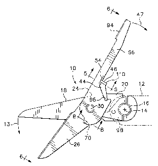
of the disclosure herein, a pair of scissors 10 is shown
in an operative configuration in FIGS. 1 and 2, extending
outward from a handle 12 shown in phantom line. The
folding scissors 10 may be stowed in a cavity defined by
the handle 12 by being rotated in the direction of the
.L5 arrow 13 about an axis 14 defined by a tool pivot shaft
16 mounted in the handle 12. A pair of scissors similar
in many respects to the scissors of the present invention
is disclosed in U.S. Patent No. 5,745,997, entitled
MULTIPURPOSE TOOL INCLUDING FOLDING SCISSORS.
The pair of scissors 10 includes a first blade
18 having a base portion 20. As shown in FIG. 2, the
base portion 20 of the first scissors blade 18 defines a
bore 22 fitted about the tool pivot shaft 16 for rotation.
The scissors 10 are movable from their stowed location
within the handle 12 to the deployed position shown in
FIGS. 1 and 2 by rotating the first blade 18 about the tool
pivot shaft 16 in the handle 12. When ready for use the
scissors 10 are in the position shown in FIG. 1.
An operating lever 24 and a second blade 26
are attached to the first blade 18 for rotation about a
scissors pivot axis 28 defined by a rivet 30 whose opposite
ends are countersunk in the first blade 18 and the
operating lever 24. Preferably, as shown in FIG. 4, a
preformed head 32 of the rivet 30 is countersunk in a
CA 02259078 1999-O1-15
6
chamfered bore 40 in the first blade 18 to ensure clear-
ance between the first blade 18 and a side wall of the
handle 12 or an adjacent tool blade in a multipurpose
tool. Slightly more clearance is normally available for
the peened outer end 34 of the rivet 30 in a chamfered
bore 35 in the operating lever 24 because of a spacer
fitted on the tool pivot shaft 16, for example, to give
clearance alongside the operating lever 24 when the scis-
sors 10 are folded as shown in FIG. 3 and stowed in a
cavity within the handle 12.
Referring still to FIG. 4, it may be seen that
the rivet 30 includes a shoulder 36 larger in diameter
than the body 38 of the rivet 30, and the body 38 extends
rotatably through a straight bore 39 through a base
portion 44 of the second blade 26. The extent of peening
the outer end 34 controls an amount of axial clearance
along the body 38 of the rivet 30, as at 41, between the
second blade 26 and the operating lever 24, when the
scissors are in the folded configuration as shown in
FIG. 3, so that the operating lever 24 is held alongside
the second blade 26. Preferably, the operating lever 24
can be moved easily from the position shown in FIG. 3 by
application of a small force, yet is not so loose that it
can simply fall out of the folded configuration.
With the shoulder 36 held closely against the
face of the second blade 26 adjacent the bore 39, the
preformed head 32 of the rivet 30 and the chamfered bore
40 in the first scissors blade 18 cooperate to keep the
second blade 26 closely alongside the first scissors
blade 18 yet permit the blades 18 and 26 to pivot with
respect to each other and the rivet 30. Alternatively,
should the rivet 30 have no such shoulder 36, the axial
clearance along the body 38 of the rivet 30 will affect
the clearance between the blades 18 and 26 during use of
the scissors. Excess clearance between the blades 18 and
26 can be taken up while still allowing the operating
lever 24 to move easily with respect to the second blade
CA 02259078 1999-O1-15
7
26 by peening the margin 42 of the preformed head 32 to
ensure that the blades cooperate closely to cut in scis-
sors fashion if the chamfered bore 40 and the preformed
head 32 do not fit each other precisely as desired.
Referring also to FIGS. 5, 6 and 7, the second
blade 26 has a base portion 44 that includes a hook 46
that extends away from the first blade 18 into the plane
of rotation of the operating lever 24 about the pivot
axis 28. Movement of the operating lever 24 in a clock-
wise direction as shown by the arrow 47 in FIGS. 1 and 2
thus brings the operating lever 24 to bear against the
hook 46. The path of the sharp edge 60 of the second
blade, as the second blade moves about the pivot axis 28,
defines a blade plane 48. The upper side of the hook 46,
at the rear of the base portion 44 of the second blade
includes an engagement surface 50 which is inclined at an
angle 52 with respect to the blade plane 48, as may be
seen in FIG. 5. A cooperating inclined engagement
surface 54 is provided on a chamfered portion of the
lower margin of the lever arm portion 56 of the operating
lever 24. The inclined engagement surfaces 50 and 54
attempt to slide along each other in response to force
applied to the operating lever 24 in a clockwise direc-
tion as shown by the arrow 47 in FIG. 1, drawing the
lever arm 56 toward the base 44 of the second blade 26
and keeping the lever arm 56 tightly engaged with the
hook 46. Further movement of the operating lever 24 in
the same direction causes the second blade 26 to rotate
clockwise about the scissors pivot axis 28 with respect
to the first blade 18 in a scissors action. This causes
respective cutting portions or edges 58 and 60 of the
scissors blades to move toward each other in a cutting or
blade-closing scissors action.
The operating lever 24 has a base portion 62
defining the bore 35 through which the rivet 30 extends
to interconnect the blades 18 and 26 with the operating
lever 24, and the respective base portions 44 and 62 of
CA 02259078 1999-O1-15
8
the second blade 26 and the operating lever 24 have
mutually confronting faces 66 and 68 seen best in FIGS. 7
and 9. A spacer 70 is provided on the second blade 26,
protruding from the confronting face 66 thereof toward
the face 68 of the base portion 62 of the operating lever
24. The spacer 70 may be a small bump, protruding from
the second blade 26 and formed as by coining, leaving a
corresponding dimple 72 in the opposite side of the
second blade as shown in FIG. 8. The spacer 70 protrudes
to a height 74 of about 0.002 inch in the form of a
circular bump having a diameter 76 of approximately 0.027
inch in one embodiment of the invention. What is
required is merely that the spacer have a height great
enough to reduce excess axial clearance along the body 38
of the rivet 30 and cock the operating lever 24 slightly,
about the pivot joint including the rivet 30, with
respect to the second blade 26, so that the lever arm 56
will be kept securely engaged with the hook 46.
A cavity 78 in the form of a shallow arcuate
groove is defined in the confronting face 68 of the base
of the operating lever, as shown in FIG. 9, and extends
through a small angle 80 measured about the pivot axis 28
of rotation of the operating lever. The cavity 78 is
located in a position corresponding with the location of
the spacer 70 when the operating lever 24 is in its
folded position extending alongside and parallel with the
second blade 26 as shown in FIG. 3. The cavity 78 has a
width 82 considerably greater than the diameter 76 of the
spacer 70, and has a depth 84 which is preferably at
least 0.002 inch greater than the height 74 of the spacer
70. Thus, when the operating lever 24 lies alongside the
second blade as shown in FIGS. 3 and 11, there is no
interference between the operating lever 24 and the
spacer 70.
A stabilizer portion 86 of the base portion 62
of the operating lever 24 extends radially away from the
scissors pivot axis 28 in a position approximately
CA 02259078 1999-O1-15
9
opposite that of the lever arm 56. The location of the
spacer 70 is approximately opposite that of the hook 46
on the second blade 26, with respect to the scissors
pivot axis 28, so that when the operating lever 24 is
moved to a position in which the engagement surface 54,
on its chamfered portion, approaches the engagement
surface 50 of the hook 46, the stabilizer portion 86
rides up onto the spacer 70. As shown in FIGS. 6 and 8,
this has the effect of slightly increasing the amount of
separation at 88, between the confronting faces 66 and 68
of the base portions 44 and 62 of the second blade 26 and
the operating lever 24, while also tending to move the
lever arm 56 toward the base portion 44 of the second
blade 26 adjacent the hook 46 to the extent permitted by
any clearance between the peened outer end 34 of the
rivet 30 and the chamfered bore 35 in the base 62 of the
operating lever 24. When the operating lever 24 is
rotated with respect to the second blade 26 away from the
position shown in FIG. 2 the stabilizer no longer engages
the spacer 70.
The operating lever 24 has a thickness 90, and
the stabilizer 86 extends radially away from the body 38
of the rivet a distance 92 sufficient to stabilize the
operating lever 24 relative to the second blade 26 and
urge the lever arm 56 toward the base 44 of the second
blade 26. For example, in the scissors 10 shown herein
the distance 92 is 0.236 inch, more than four times the
thickness 90, which is 0.040 inch.
A handle tab 94 on the operating lever 24
extends transversely in the direction toward the blades
18 and 26. The tab 94 provides a surface against which
to push comfortably to operate the scissors and is spaced
far enough away from the scissors pivot axis 28 that the
tab 94 passes clear of the tips of the blades 18 and 26
as the scissors 10 are folded to the configuration shown
in FIG. 3. When the scissors 10 are folded the cutting
portions or edges 58 and 60, respectively, of the first
CA 02259078 1999-O1-15
and second scissors blades 18 and 26 are in a fully
closed position.
A small ear defines a notch 96 in the base
portion 62 of the operating lever 24 that can be engaged
5 by a fingernail to start to move the operating lever 24
from its folded position, far enough to raise the tab 94
from within the handle 12 far enough to be gripped.
A rocker 98 includes a pin 100 extending to the
far side of the rocker 98, as shown in FIG. 7, and the
10 base portion 20 of the first blade 18 defines a corre-
sponding hole 102 into which the pin 100 protrudes
laterally from the rocker 98 so that movement of the
first blade 18 more than a small distance about the axis
14 also moves the rocker 98 linked to the first blade 18
by the interaction of the pin 100 and the hole 102.
As the operating lever 24 is rotated in a
clockwise direction beyond the position shown in FIGS. 1
and 2, moving the edges 58 and 60 along each other,
further movement of the blade 26 about the axis 28 pushes
the base portion 44 of the second blade 26 toward and
into contact with the rocker 100. The rocker 100 limits
movement of the second blade 26 beyond a closed position
with respect to the first blade 18 so that subsequent
clockwise movement of the operating lever 24 as shown in
FIG. 1 moves the entire folding scissors 10 clockwise by
moving the first scissors blade 18 about the tool pivot
shaft 16. The base portion 20 of the first blade 18
includes a stop that abuts against the handle 12 to limit
movement of the first blade 18 relative to the handle 12
in a clockwise direction about the tool pivot shaft 16 at
the appropriate position.
When the scissors 10 are in the operating
configuration a spring (not shown) urges the rocker 98 to
rotate in a clockwise direction relative to the first
blade 18 as shown in FIG. 1 until a finger 104 on an
outer end of the rocker 98 presses against the base
portion 44 of the second blade 26 as shown in FIG. 7.
CA 02259078 1999-O1-15
11
The rocker 98 thus urges the second blade 26 to move in a
counterclockwise direction, opening the cutting edges 56
and 58 apart from each other toward an open position of
the scissors blades 18 and 26. The hook 46 of the second
blade 26 presses in reaction against the operating
lever 24, carrying the operating lever 24 along with
counterclockwise opening movement of the second blade 26.
To use the scissors to cut an object, then, it
is merely necessary to push against the handle tab 94 of
the operating lever 24, urging it toward the handle 12 as
indicated by the arrow 47. This rotates the second blade
26 clockwise about the scissors pivot axis 28 and moves
the cutting edges 56 and 58 closer together and along
each other in a normal scissors cutting motion.
As shown in FIG. 12, the hook 46 may be made by
cutting a flat sheet of metal to define a concave portion
106 in a margin of a rear portion 44 of the second blade
26. A bend is formed near or along the line 108 to form
the hook 46 so that the engagement surface 50 is then
oriented to mate against the engagement surface 54 of the
lever arm 56. Thereafter, the outer end face 110 is
defined by cutting as necessary so that the hook 46
extends no further than the thickness of the operating
lever 24, as shown best in FIGS. 5, 6 and 11.
The terms and expressions which have been
employed in the foregoing specification are used therein
as terms of description and not of limitation, and there
is no intention, in the use of such terms and expres-
sions, of excluding equivalents of the features shown and
described or portions thereof, it being recognized that
the scope of the invention is defined and limited only by
the claims which follow.