Language selection

Search

Patent 2259092 Summary

Third-party information liability

Some of the information on this Web page has been provided by external sources. The Government of Canada is not responsible for the accuracy, reliability or currency of the information supplied by external sources. Users wishing to rely upon this information should consult directly with the source of the information. Content provided by external sources is not subject to official languages, privacy and accessibility requirements.

Claims and Abstract availability

Any discrepancies in the text and image of the Claims and Abstract are due to differing posting times. Text of the Claims and Abstract are posted:

  • At the time the application is open to public inspection;
  • At the time of issue of the patent (grant).
(12) Patent: (11) CA 2259092
(54) English Title: COOLING PLATE FOR SHAFT FURNACES
(54) French Title: PLAQUE DE REFROIDISSEMENT POUR FOURS A CUVE DE FUSION
Status: Deemed expired
Bibliographic Data
(51) International Patent Classification (IPC):
  • F27D 1/12 (2006.01)
  • C21B 7/10 (2006.01)
(72) Inventors :
  • SMIALEK, KARL-HEINZ (Germany)
  • HILLE, HARTMUT (Germany)
  • OTREMBA, WERNER (Germany)
  • HEINRICH, PETER (Germany)
(73) Owners :
  • SMS SCHLOEMANN-SIEMAG AKTIENGESELLSCHAFT (Germany)
(71) Applicants :
  • SMS SCHLOEMANN-SIEMAG AKTIENGESELLSCHAFT (Germany)
(74) Agent: RICHES, MCKENZIE & HERBERT LLP
(74) Associate agent:
(45) Issued: 2006-11-14
(22) Filed Date: 1999-01-15
(41) Open to Public Inspection: 1999-07-16
Examination requested: 2003-12-31
Availability of licence: N/A
(25) Language of filing: English

Patent Cooperation Treaty (PCT): No

(30) Application Priority Data:
Application No. Country/Territory Date
198 01 425.2 Germany 1998-01-16

Abstracts

English Abstract


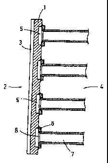
A cooling plate for shaft furnaces, particularly blast
furnaces, is provided with a refractory lining and is composed of
copper or a low-alloy copper alloy with cooling medium ducts,
wherein the cooling plate is made from a wrought or rolled ingot,
and wherein the cooling plate has on one side thereof, i.e., the
front side, grooves for receiving refractory material. Cooling
ducts are provided on the rear side of the cooling plate, wherein
the cooling ducts are defined in part by the cooling plate itself
and in part by sheet metal or sheet steel, wherein the cooling
ducts are produced by milling cutting in the rear sides of the
cooling plate and/or the sheet metal or sheet steel.


Claims

Note: Claims are shown in the official language in which they were submitted.


The embodiments of the invention in which an exclusive
property or privilege is claimed are defined as follows:
1. A cooling plate for shaft furnaces, provided with a
refractory lining, wherein the cooling plate is composed of
copper or a low-alloy copper alloy and is manufactured from
a wrought or rolled ingot, the cooling plate having a front
side and a rear side, the cooling plate comprising grooves
on the front side thereof for receiving refractory material,
further comprising cooling ducts on the rear side of the
cooling plate, the cooling ducts being partially defined by
the cooling plate and partially by sheet metal pieces, the
cooling ducts comprised of open, recessed milled ducts in
the rear side of the cooling plate covered by the sheet
metal pieces.
2. The cooling plate according to claim 1, wherein the
cooling ducts are in addition formed by deep-drawing or
bending of the sheet metal pieces.
3. The cooling plate according to claim 1, wherein the
open, recessed milled ducts have a width and a depth,
wherein the width is greater than the depth.
4. The cooling plate according to claim 1, wherein the
sheet metal pieces are of steel.
5. The cooling plate according to claim 1, wherein the
sheet metal pieces are of copper.
9


6. A cooling plate for shaft furnaces provided with a
refractory lining, wherein the cooling plate is composed of
copper or a low-alloy copper alloy and is manufactured from
a wrought or rolled ingot, the cooling plate having a front
side and a rear side, the cooling plate comprising grooves
on the front side thereof for receiving refractory material,
further comprising cooling ducts on the rear side of the
cooling plate, the cooling ducts being partially defined by
the cooling plate and partially by a sheet metal plate, the
cooling ducts comprised of open, recessed milled ducts in
the rear side of the cooling plate covered by the sheet
metal plate.
7. The cooling plate according to claim 1, wherein the
sheet metal pieces are at least one of welded and screwed to
the cooling plate.
8. The cooling plate according to claim 6, wherein the
sheet metal plate is at least one of welded and screwed to
the cooling plate.
9. The cooling plate according to any one of claims 1 to
8, wherein the shaft furnace is a blast furnace.

Description

Note: Descriptions are shown in the official language in which they were submitted.


CA 02259092 1999-O1-15
COOLING PLATE FOR SHAFT FURNACES
BACKGRODND OF THE INVENTION
1. Field of the Invention
The present invention relates to cooling plates for shaft
furnaces, particularly blast furnaces, provided with a refractory
lining. The cooling plates are composed of copper or a low-alloy
copper alloy with cooling medium ducts, wherein the cooling
plates are made from a wrought or rolled ingot, and wherein the
cooling plates have on one side thereof, i.e., the front side,
grooves for receiving refractory material.
2. Description of the Related Art
Cooling plates of the above-described type are disclosed in
German Patent 29 07 511. In these cooling plates, the cooling
ducts are provided in the wrought or rolled ingot in the form of
vertically extending blind-end bores which are produced by
mechanical deep drilling. Cooling plates of this type must.have
a relatively great thickness to make it possible to bore the
cooling ducts without impairing the stability of the cooling
plates. On the front sides as well as on the rear sides of the
cooling plates sufficient copper material must remain in the
1

CA 02259092 1999-O1-15
areas of the bores in order to ensure that the cooling plates
have sufficient strength. Consequently, very thick copper plates
are required which are correspondingly very expensive because of
the high price of copper.
Since the cooling ducts are produced by drilling into the
cooling plates, only circular holes can be made. These circular
blind-end bores have only relatively small surfaces at which the
required heat exchange from the cooling plates to the cooling
medium can take place. Consequently, only a poor heat transfer
is achieved.
2

CA 02259092 1999-O1-15
SUMMARY OF THE INVENTION
Therefore, it is the primary object of the present invention
to construct cooling plates of the above-described type in such a
way that they are less expensive and better cooling efficiencies
can be achieved.
In accordance with the present invention, cooling ducts are
provided on the rear sides of the cooling plates, wherein the
cooling ducts are defined in part by the cooling plate itself and
in part by sheet metal or sheet steel, wherein the cooling.ducts
are produced by milling cutting in the rear sides of the cooling
plates and/or the sheet metal or sheet steel.
The configuration according to the present invention makes
it possible to use substantially thinner cooling plates because
it is only necessary to provide one web of suitable thickness
between the front side and the cooling duct. The second part of
the cooling duct can be formed by other material, such as steel,
which may have a much smaller thickness.
Since the cooling ducts are produced by milling the cooling
plates, any desired cross-sectional shapes and patterns of the

CA 02259092 1999-O1-15
cooling ducts may be realized. It is not necessary, as is the
case in blind-end bores, to produce always straight ducts. This
makes it possible to place the cooling ducts at any desired
location of the cooling plates, so that the cooling plates can be
cooled more uniformly.
If ducts with great widths and small depths are selected,
large surface areas of the cooling plates are directly contacted
by the cooling medium, so that a high heat discharge is possible.
The cooling ducts provided on the cooling plate can be
closed off by individual sheet metal pieces or an entire plate.
It is essential that the ducts are closed off tightly, for
example, by welding or screwing the sheet metal pieces or plates
to the cooling plates.
It is certainly also possible to weld cooling plates
constructed with the cooling ducts against a flat rear side of
the cooling plate. These sheet metal pieces can be manufactured,
for example, by deep-drawing or bending, so that the
manufacturing costs for the cooling plates are especially low.
In that case, particularly thin cooling plates can be
4

CA 02259092 2004-11-03
manufactured which, in turn, means that expensive copper can
be saved.
The various features of novelty which characterize the
invention are pointed out with particularity in the claims
annexed to and forming a part of the disclosure. For a
better understanding of the invention, its operating
advantages, specific objects attained by its use, reference
should be had to the drawing and descriptive matter in which
there are illustrated and described preferred embodiments of
the invention.
In a further aspect, the present invention provides a
cooling plate for shaft furnaces, provided with a refractory
lining, wherein the cooling plate is composed of copper or a
low-alloy copper alloy and is manufactured from a wrought or
rolled ingot, the cooling plate having a front side and a
rear side, the cooling plate comprising grooves on the front
side thereof for receiving refractory material, further
comprising cooling ducts on the rear side of the cooling
plate, the cooling ducts being partially defined by the
cooling plate and partially by sheet metal pieces, the
coo:Ling ducts comprised of open, recessed milled ducts in
the rear side of the cooling plate covered by the sheet
metal pieces.
In a still further aspect, the present invention
provides a cooling plate for shaft furnaces provided with a
refractory lining, wherein the cooling plate is composed of
copper or a low-alloy copper alloy and is manufactured from

CA 02259092 2004-11-03
a wrought or rolled ingot, the cooling plate having a front
side and a rear side, the cooling plate comprising grooves
on the front side thereof for receiving refractory material,
further comprising cooling ducts on the rear side of the
cooling plate, the cooling ducts being partially defined by
the cooling plate and partially by a sheet metal plate, the
cooling ducts comprised of open, recessed milled ducts in
the rear side of the cooling plate covered by the sheet
metal plate.
5a

CA 02259092 1999-O1-15
BRIEF DESCRIPTION OF THE DRAWING
In the drawing:
Fig. 1 is a cross-sectional view of a cooling plate with
several cooling ducts; and
Fig. 2 is a side view of a cooling plate mounted in a blast
furnace.
6

CA 02259092 1999-O1-15
DESCRIPTION OF THE PREFERRED EMBODIMENTS
Fig. 1 of the drawing shows a cooling plate 1 which on its
front side 2 has grooves 3 which are intended for receiving
refractory material.
Cooling medium ducts 5 are milled into the rear side 4 of
the cooling plate 1. These ducts are not milled very deep into
the rear side 4, however, they have a relatively great width.
The ducts 5 are closed by sheet metal or steel pieces 6. The
sheet metal or steel pieces 6 are welded onto the cooling plate
1.
The sheet metal or steel pieces 6 simultaneously serve to
receive supply and discharge lines 7 for the cooling medium. The
supply and discharge lines 7 are welded into the bores 8 of the
sheet metal or steel pieces 6.
Fig. 2 shows the inner wall 9 of a blast furnace with a-
cooling plate 1 screwed onto the inner wall 9. In this case, the
rear side 4 of the cooling plate provided with the cooling medium
ducts 5 is not closed by a plurality of sheet metal or steel
pieces 6, but by a single plate 6'.
7

CA 02259092 1999-O1-15
The invention is not limited by the embodiments described
above which are presented as examples only but can be modified in
various ways within the scope of protection defined by the
appended patent claims.
8

Representative Drawing
A single figure which represents the drawing illustrating the invention.
Administrative Status

For a clearer understanding of the status of the application/patent presented on this page, the site Disclaimer , as well as the definitions for Patent , Administrative Status , Maintenance Fee  and Payment History  should be consulted.

Administrative Status

Title Date
Forecasted Issue Date 2006-11-14
(22) Filed 1999-01-15
(41) Open to Public Inspection 1999-07-16
Examination Requested 2003-12-31
(45) Issued 2006-11-14
Deemed Expired 2009-01-15

Abandonment History

There is no abandonment history.

Payment History

Fee Type Anniversary Year Due Date Amount Paid Paid Date
Application Fee $300.00 1999-01-15
Registration of a document - section 124 $100.00 2000-01-14
Maintenance Fee - Application - New Act 2 2001-01-15 $100.00 2000-12-20
Maintenance Fee - Application - New Act 3 2002-01-15 $100.00 2001-12-14
Maintenance Fee - Application - New Act 4 2003-01-15 $100.00 2002-12-16
Maintenance Fee - Application - New Act 5 2004-01-15 $150.00 2003-12-23
Request for Examination $400.00 2003-12-31
Maintenance Fee - Application - New Act 6 2005-01-17 $200.00 2004-12-30
Maintenance Fee - Application - New Act 7 2006-01-16 $200.00 2005-12-16
Final Fee $300.00 2006-08-14
Maintenance Fee - Patent - New Act 8 2007-01-15 $200.00 2006-12-20
Owners on Record

Note: Records showing the ownership history in alphabetical order.

Current Owners on Record
SMS SCHLOEMANN-SIEMAG AKTIENGESELLSCHAFT
Past Owners on Record
HEINRICH, PETER
HILLE, HARTMUT
OTREMBA, WERNER
SMIALEK, KARL-HEINZ
Past Owners that do not appear in the "Owners on Record" listing will appear in other documentation within the application.
Documents

To view selected files, please enter reCAPTCHA code :


To view images, click a link in the Document Description column. To download the documents, select one or more checkboxes in the first column and then click the "Download Selected in PDF format (Zip Archive)" or the "Download Selected as Single PDF" button.

List of published and non-published patent-specific documents on the CPD .

If you have any difficulty accessing content, you can call the Client Service Centre at 1-866-997-1936 or send them an e-mail at CIPO Client Service Centre.


Document
Description 
Date
(yyyy-mm-dd) 
Number of pages   Size of Image (KB) 
Abstract 1999-01-15 1 21
Description 1999-01-15 8 166
Representative Drawing 1999-08-09 1 6
Claims 1999-01-15 3 60
Drawings 1999-01-15 2 27
Cover Page 1999-08-09 1 34
Description 2004-11-03 9 203
Claims 2004-11-03 2 60
Cover Page 2006-10-17 1 37
Representative Drawing 2006-10-17 1 8
Correspondence 1999-02-23 1 31
Assignment 1999-01-15 3 97
Correspondence 2000-01-14 2 69
Assignment 2000-01-14 4 141
Correspondence 2000-01-14 2 60
Assignment 2000-02-09 4 139
Correspondence 2004-01-05 2 71
Prosecution-Amendment 2003-12-31 1 48
Correspondence 2004-03-12 1 15
Correspondence 2004-03-12 1 18
Prosecution-Amendment 2004-11-03 7 186
Fees 2005-12-16 1 34
Correspondence 2006-08-14 1 46