Note: Descriptions are shown in the official language in which they were submitted.
CA 02259244 1998-12-24
WO 98/00031 1 PCT/DK97/00286
A method and a system with a release thawing station for
the production of frozen confectioneries, in particular
edible ice bodies.
- The present invention concerns a method for making
frozen confectionery products, especially edible ice bodies,
which are frozen while they are in supporting contact with a
support surface like a mould or a support plate which is sub-
s jetted to a short-period heating by a heating medium for lib-
erating the frozen product. Generally, when using common
freezing technique the products will freeze on to the sur-
faces they are in contact with. In some productions the fro-
zen products may be detached by mechanical scraping, but it
is more common that they are loosened by heating the contact
surface, which is particularly relevant with decidedly
moulded products. Normally the contact surfaces will be good
heat transmitters because they are used actively in the
freezing process, and therefore they are also relative-ly
easy to heat up for achieving a sufficient melting loose of
the product surface frozen on to the contact surface.
In production apparatus for moulded edible ice bod-
ies it is common to place the freezing moulds in rows and
projecting downward from upper support lamellar plates which
in chain formation are conveyed over a freezing bath with the
freezing moulds projecting downward into the bath. As the
lamellar plates reach the outlet end of the bath they are
lifted up from it for a subsequent lowering into a bath with
warm water, where they subsequent to an additional short for-
ward run are ready to liberate the products.
By the present invention it is found possible to
indicate a method by which the melting loose may be performed
in an even more advantageous way, i.e. both faster and more
uniformly. For an effective melting loose it is required that
all part areas of surfaces frozen solid are melted, and there
may very well appear differences in the degree of freeze in
such a way that for one or more part areas it is necessary
with more heat for melting than in other part areas; in this
way, the run through the warm water bath or in a loading zone
for warm air has to be sufficiently prolonged in order that
also the more heat demanding areas will get to thaw and this
implies both a relatively long run and an unnecessary exten-
CA 02259244 1998-12-24
WO 98/00031 PCT/DK97/00286
2
sive melting of the surface areas that are thawed loose in
the first place.
By the invention is has been observed that by using
hot steam as thawing medium surprisingly good results with
respect to uniformity, speed, and energy consumption have
been achieved. At the outset there is used an annular nozzle
which is utilized with a fast upward and downward movement
for sending jets of hot steam (100-150°) directly against the
outer wall of a cold ice lolly mould, whereby the ice lolly
may be freely drawn up after a period in the magnitude of 1
second. We are speaking of an extremely effective heat trans-
mission produced by a instantaneous phase shift from gas to
ice/liquid phase at the contact of the hot steam with the
cold mould wall parts maybe having a temperature from -20° to
-30°, whereby a high local vacuum is created, carrying with
it new steam with high speed, i.e. with the speed of sound.
Thereby the warming up of the moulds becomes self-increasing.
An important fact is that hereby self-equalizing of
the warming up will take place, since colder areas will auto-
matically attract more steam than less cold areas. Further-
more, such a heat accumulation in the outer layer of the
mould will take place so quickly that during a last stage of
the thawing the heat will be distributed inwardly in a way
almost controlled by demand, possibly after termination of
the heat supply. With certain moulds it is hereby possible to
work with an active warming up period of about 0.1 second,
with an effective demoulding a few tenths of a second there-
after.
Even though the heat transmission in the moulds is
not completely uniform with the said short thawing period
there will no time for any further melting of the parts of
the surfaces of the product situated at the areas with the
highest heat transmission ability, and the length of the
thawing zone, which conventionally cf. the example herei-
nabove is 12 lamellar widths, may be reduced to a single
lamellar width, a fact which shortens the overall length of
the apparatus or increases its capacity.
CA 02259244 2004-11-12
3
The heat energy used for the thawing is minimized
because it is only the moulds that are heated, which also has
the consequence that the subsequent renewed cooling only re-
quires recooling of the moulds and not of the other moved
parts. Thereby about 10-15% cooling power may be saved. The
heat supply may easily be stopped and minimized by regulating
the steam pressure.
Since the hot steam is sterile the method will hy
gienically advantageous, and besides that the system may be
applied for sterilization of the moulds and the lamellas in
that by slowing the rate of work of the apparatus when run-
ning idle it is possible to utilize the steam for heating
these parts to 100°.
Normally the ice factories in question will already
have a steam installation and therefore the invention will
mean low investment and operating costs.
In ice making machines using cold air for freezing
the products the invention may be realized in a simple and
advantageous way in that the said annular nozzle may be util-
ized directly in the freezing compartment, since the energy
supplied for thawing loose wil be concentrated on the moulds
in such a way that the direct heat exchange with the freezing
air will be minimal. Thereby no separation of the compartment
between the freezing and the thawing sections will be neces-
sary, and the occurring energy waste will be rather small.
It is important to note that the use of the said
annular nozzle indicates a functional ideal which in an ac-
ceptable way may be given free in practice. So if working in
a usual way with transversely positioned rows of moulds in a
conveying system it is a favourable opportunity just to use
two mutually oppositely situated nozzle beams which then may
service a whole row of moulds at a time. Preferably there is
utilized a box-shaped body which uppermost has nozzle outlets
on its inside and which at the bottom has a connection for a
suction source.
CA 02259244 2004-11-12
3a
According to one aspect of the present invention,
there is provided an apparatus for making frozen
confectionery bodies comprising a conveying device for
freezing molds for moving the molds through a filling
station and a freezing zone to a de-molding station,
wherein thawing means for heating the molds to loosen the
frozen bodies for removal thereof from the molds, the
thawing means comprising means for supplying hot steam to
the exterior of the molds and a mantle member surrounding
at least one of the molds, a narrow space being formed
between the at least one mold and the mantle member, the
mantle member having nozzle means connected with a hot
steam supply source for injecting hot steam into and along
the narrow space towards an outlet area from which air and
steam are released from the narrow space.
According to a further aspect of the present
invention, there is provided a method for making frozen
confectionery bodies by freeze molding in individual molds
and subsequently externally applying steam to the molds for
loosening and removing the frozen bodies from the molds,
comprising the steps of arranging at least one of the molds
inside a mantle member having inner surface portions
located slightly spaced from outer surface portions of the
mold so as to create a narrow space between the mold and
the mantle member, and injecting hot steam into and along
the narrow space towards an outlet therefrom, the steam
expelling air from the narrow space so as to intensify the
heating effect of the steam on the mold.
The invention will be explained in the following
with reference to the drawing, on which
CA 02259244 1998-12-24
WO 98/00031 PCT/DK97/00286
4
Fig. 1 is a schematic overview of an ice production
plant,
Fig. 2 is a perspective view of some freezing
moulds therein with a schematically shown thawing unit ac-
s cording to the invention,
Fig. 3 is a more detailled sectional view of a such
unit in a slightly modified form,
Fig. 4 is a schematic perspective view correspond-
ing to Fig. 2, but of a changed embodiment of the freeze
moulds and the means for thawing loose,
Fig. 5 and 6 are sectional views for illustrating
the working area of the thawing means, and
Fig. 7 is a schematic sectional view showing fur-
ther embodiments.
The plant shown on Fig. 1 comprises an apparatus
housing 2, in which in a not shown way there is conveyed a
belt with downwardly projecting freezing moulds which are
filled with relevant confectionery or ice mass in a filling
station, whereafter the moulds when passing a freezing zone
are cooled for an initial freezing of their contents, so that
in an action station 6 carrying or handling sticks or pins
may be placed in the semifrozen bodies in the moulds. These
are then subjected to further cooling in the freezing zone,
and when the moulded bodies are frozen to a desirable degree
they come to a thawing station 8, wherein the moulds are
warmed up sufficiently for freely drawing up the moulded bod-
ies from the moulds, which action may take place in the same
or in a subsequent station 10. Thereafter the moulds are re-
turned to the filling station, which is symbolically marked
as a return station 12, which, however, may also represent a
mould cleaning station.
In the present connection the thawing station 8 is
in focus and it is really without significance how the plant
is designed besides that. The said support belt may extend
around in the horizontal or vertical plane, and the mould
freezing may take place using cold air or more conventionally
by the use of freeze brine.
CA 02259244 1998-12-24
WO 98/00031 PCT/DK97/00286
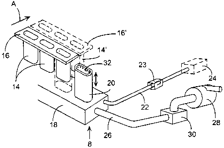
In Fig. 2 it is implied, that the shown freezing
moulds 14 may be placed as rows on transversely positioned
support lamellar plates 16 conveyed in a beltwise manner in
the direction shown with arrow A. In regular production fa-
5 cilities there is used a large number of freezing moulds, so
that it is possible to work with a production capacity of
typically 20-40.000 units per hour.
Cf. Fig. 2 the lamellar plate 161 shown with punctu
ated lines with corresponding freezing moulds 141 has reached
a position in the thawing station 8 in which according to the
invention there is placed an underlying transverse beam 18
carrying a number of upright standing cylindrical bodies 20
with such a shape and position that these bodies can be
slided upwardly for confining the respective freezing moulds
141 by raising the transverse beam 18 or possibly by a corre-
sponding lowering of the lamellar plate 161.
The transversal beam is connected to a supply pipe
22 for hot steam from a steam source 24 together with a drain
pipe 26 leading to an exhaust fan 28 via a steam trap 30. The
cylindrical bodies 20 are shown as double walled cup bodies
with an upper annular row of nozzle holes 32 in the inner
wall. These holes are in a not shown way connected to the
steam source 22 via a valve 23, and in the bottom of the cup
bodies there is a connection to the suction pipe 26.
The transversal beam 18 may in this way be raised
for achieving that the cup bodies 20 are slided upwardly for
accomodating the moulds 141, and if or when the valve 23 is
opened hereby the said steam heating of the moulds will take
place during the raising of the ring of nozzle holes 32 which
will send jets of hot steam, e.g. at a pressure of 3 bar, di-
rectly against the mould walls. This treatment may continue
or be repeated during the subsequent lowering of the trans-
verse beam, but depending on the raising/lowering speed of
the transversal beam it may be sufficient to keep the valve
23 open only during either raising or lowering. The suction
from the pipe 26 counteracts pressure accumulation in the
process compartment as well as it sucks up occurring conden-
sate.
CA 02259244 1998-12-24
WO 98/00031 PCT/DK97/00286
6
Immediately hereafter the ice bodies are drawn up
from the moulds 141 by lifting the mounted sticks, whether
these are permanent handle sticks or special carrying pins
that are pulled out in a subsequent station from the ice bod-
y ies for automatic returning to the insertion station 6.
As implied in the above by using transversely
placed rows of moulds - i.e. just as the case is in Fig. 2 -
it is possible to abstain from utilizing the individual cup
bodies 20, in that instead an upwardly open box structure may
be used which in a corresponding way act on the moulds only
from the respective opposite longitudinal sides, and such a
unit is shown in section in Fig. 3. On the hollow transversal
beam 18 there is mounted a top section 36 and a box body 38
projecting upward therefrom, the longitudinal sides of which
body 38 are made up of double walls 40 connected at the bot-
tom to longitudinally extending ducts 42 in the top section
36, while they at the top have inwardly facing nozzle holes
or slits 44. The ducts 42 are connected with the steam supply
22, and at the bottom they have some minor holes or slits 46
for draining condensate from the inner compartments in the
double walls. The bottom of the box body 38 is communicating
with the hollow compartment in the beam 18 through a slot 48
and thereby also with the suction pipe 26.
In this embodiment there will not appear any steam
jets directly against the narrow sides of the moulds 141, but
as mentioned before the cold surfaces in question will even
suck the steam supplied to the spaces between the moulds to
themselves, whereby the efficiency becomes very good anyway.
In the embodiment shown on Fig. 4 the tranversely
positioned support plates 16, cf. Fig. 2, are made with in-
dentations 50 for forming moulds for spheric ice bodies 52
without inserted sticks. When the plates 16 reach the thawing
station they are turned 180° and are placed on a support
plate 54 above which there is placed a thawing unit 56 to be
lowered over the moulds 50 now facing upwards. Furthermore,
in this station there is provided not shown means for lifting
the plates 16.
CA 02259244 1998-12-24
WO 98/00031 PCT/DK97/00286
7
Inside the unit 56 there is provided a device 58 as
shown more closely in Fig. 5 for each of the moulds 50. This
device has a top section 60 with connections 62 and 64 for
the steam pipe 22 and for pressurized air from a controlled
air valve 66, respectively. The top section 60 has a lower
boring 68 accomodating an upward projecting neck piece 70 on
a lower shell section 72 that is shaped approximately corre-
sponding to the outside of the mould 50, but just slightly
larger than this. Around the lower part of the neck piece 70
in the top section 60 there is shaped a recess 74 which
through a drilling 76 is communicating with the steam supply
62. The shell body 72,70 is made with an annular abutment 78
for sealingly abutting against the lower outer edge of the
top section 60, i.e. it will be able to receive otherwise
shaped shell bodies if only these are designed in a standard-
ized way at the top. The recess 74 will then be closed down-
wards by means of an upper part of the shell piece 72, and
exactly in this some holes 80 for downward steam jets from
the recess 74 are drilled.
At its lower annular edge the shell part 72 has a
downward facing sealing ring 82 which by lowering the whole
device may provide a sealing abutment against the presently
upward facing underside of the mould plate 16 outside around
the mould 50. Between the mould edge and the sealing area in
question there is provided some holes or slits 84 in the
plate 16 for permitting evasion of air and steam from the
compartment designated 86 between the shell part 72 and the
mould 50 when steam is blown down through the holes 80.
The neck piece 70 is provided with a central boring
in which there is accomodated a hollow pin 88 with a lower
main section 90 provided with a downward facing sealing ring
92 around a central passageway 94 in the pin 88. The ring 92
is intended for abutting against the upper central area of
the upwardly bulging mould 50 which just at this point has a
small hole 96, so small that in the normal position of the
mould it will not allow an outflow of the viscous freeze mass
initially filled into the moulds 50. The hollow pin 88 may be
slided upwardly against the action of a spring force.
CA 02259244 1998-12-24
WO 98/00031 PCT/DK97/00286
8
When the unit 54, Fig. 4, has been lowered against
the overturned mould plate 16 the situation appears as shown
in Fig. 5. When the steam valve 23 is opened pressurized
steam will be led to the compartment 86 through drilling 76,
recess 74, and the holes 80 so that hot steam will sweep down
along the external side of the mould 50, while air and exces-
sive steam will evade through perforations 84 in the plate
16. While this plate may be a very thin metal sheet of e.g.
stainless steel, and the mould sections 50 may be made of
such a material and separately fastened to the support plate
16, the operation of thawing loose itself may hereby be per-
formed extremely quickly so that it may be sufficient to sup-
ply steam during 1/10 of a second.
For performing a secure, active removal of moulds
pressurized air may be supplied through connection 64 - or
possibly even pressurized steam - to the boring 68, whereby
this pressure medium will act on the hollow pin 88 with a
downward force, causing a efficient sealing at the ring 92,
and will be conveyed through the passageway 94 and the hole
96 in the mould 50, so that the free-thawed ice body 52 will
be acted on with a push downward of the mould 50. Such a
pushing may take place when the support plate 16 is lifted
more or less from the plate 54, e.g. just as indicated in
Fig. 5, where the plate 54 is shown punctuated with a short
distance below the plate 16.
Moreover, the main parts in question should then be
lifted free from each other in order to permit further trans-
port of both demoulded ice bodies 52 and the left mould
plates 16, and such a required detachment is shown in Fig. 6.
It is a qualified part aspect of the invention that
in the bottom of a casting or freezing mould a hole 96 may
occur which do not allow outflow of the filled mass, but
which later allow injection of a pressurized medium for ex-
pelling the cast or frozen body from the mould. Possibly
there may be utilized means for a temporary blocking of the
hole so that also low viscous masses may be retained.
It should be mentioned that the device shown in
Fig. 5 may very well be used in the reversed position, i.e.
CA 02259244 1998-12-24
WO 98/00031 PCT/DK97/00286
9
without overturning the moulds, if only supplementary means
for picking up the ice bodies are used, e.g. carrying pins or
sucking discs.
The invention relates to performing all kinds of
tasks pertaining to free-thawing including also the thawing
free of ice products which in a simple way appear as lumps on
a conveyed support belt, for example after cutting off pieces
from an extruded run of the material to be frozen. In a sub-
sequent, further freezing these pieces may very well adhere
to the support belt, and a quick free-thawing may be achieved
by supplying hot steam to the underside of the belt on the
relevant spot.
On Fig. 7 there is shown a slightly curved convey-
ing track of a support belt 98, which also could be straight,
with lumps 100 of ice mass laid thereon, and where the lumps
100 can occur situated either completely at the outer side of
the belt or in outer indentations 102 therein. At the free-
thawing station in question there is arranged a permanent or
a movable screen 104 through which hot steam may be injected
for achieving a very quick local warming up of the support
surface for the ice bodies 100 and thereby an effective lib-
eration of these.