Note: Descriptions are shown in the official language in which they were submitted.
CA 02259705 2006-12-21
-1-
REINFORCING MEMBER FOR COMPOSITE
WORKPIECES AND ASSOCIATED METHODS
FIELD OF THE INVENTION
This invention relates to fiber reinforced composite
structures, and more particularly relates to reinforcing
members for such composite structures.
BACKGROUND OF THE INVENTION
In relatively recent years, fiber reinforced
composite parts have replaced parts and components
previously made of structural metals, such as steel,
aluminum and the like. This is particularly true in the
aircraft industry, where it is recognized that the
reinforced composite components can provide at least the
same degree of strength and structural integrity as
conventional materials, and oftentimes with significantly
less weight and cost. Many of the reinforced components
are made with reinforced cloth, which is ultimately
formed to a desired shape, impregnated with a hardenable
resin and cured to form a rigid structure.
The advantages achieved by stitching, such as, for
example, loop stitching through fiber
CA 02259705 1999-01-20
-2-
reinforced composite components for reinforcing two
abutting components in a secured position and to resist
delamination and peel forces, has been well
established. See, for example, U.S. Patent No.
4,256,790 to Lackman, et al., which teaches the sewing
of a series of stitches through the thickness of panels
while they are in a staged condition, which allows the
two panels to be co-cured as assembled and form a
strong reinforced composite structure. U.S. Patent No.
4,206,895 to Olez, also discloses the strengthening of
a joint in a bonded fiber structure of two or more
fiber reinforced components by the use of high strength
threads inserted through the joint.
Obtaining a three-dimensional reinforcement
in a tight, restricted area, as, for example, between
stiffeners and intercostals of a stiffened skin
structure, is difficult, and in many cases, virtually
impossible with conventional stitching machines. The
use of stitching, as, for example, shown in the Olez
Patent No. 4,206,895, and in the Lackman, et al. Patent
No. 4,256,790, has improved damage tolerance and
resistance to delamination, peel and tensile pull-off
loads. Moreover, this three-dimensional stitching has
been found to be effective in reducing in-plane shear
in laminated structures.
Due to the size and construction of
conventional stitching machines, however, the location
and the overall size of the bobbins (or loopers, which
are used in chain stitching) greatly restrict the area
in which stitching may be accomplished. Consequentlv,
in many areas where three-dimensional reinforcement
would be desired, conventional automatic stitching is
not an option because of the difficulty, if not
impossibility, of operating the stitching machines in
confined and restricted areas.
Tufting has also been considered as a means
of three-dimensional reinforcement in confined and
CA 02259705 1999-01-20
-3-
restricted areas. However, tufting is limited in that
it does not retain the compaction of the dry fiber
preforms which is achieved by conventional stitching
which is not tufted.
Stapling, although having some advantages, is
usually performed with staples formed of metal, and
metal in certain cases may be unacceptable. As a
simple example, metal components are electrically
conductive, and electrical conductivity may be
undesirable in certain applications. Effective
thermoplastic staples are not yet available. There
have even been attempts to make individual pins from
carbon fibers and a thermoplastic resin, which are
extruded. However, these pins are very costly to make,
and furthermore, they are quite labor-intensive when
installed, even though they may improve the desired
properties of the components in which they are used.
U.S. Patent No. 4,528,051 to Heinze, et al.
discloses a method for strengthening fiber reinforced
components using a multitude of metal or synthetic
material pins driven into the layers of fibers and
resin of adjacent structural components. The resin is
then cured with the pins in place to improve the
strength of the structural components and to prevent
the peeling of one layer away from an adjacent layer.
In certain embodiments, the pins are flexible and
formed of Kevlar'~ thread. A stitching mechanism or
sewing machine is used to insert the threads. As such,
these embodiments suffer from the disadvantage noted
above; namely, that the stitching operation cannot be
performed in confined and restricted areas.
Other embodiments of the Heinze patent use
stiff metal pins inserted in a pin carrier in the form
a belt or webbing. The webbing may be bonded to one of
the fiber reinforced composite components after the
metal pins have been inserted. However, the use of
conductive metal compon~-nts can be disadvantageous as
CA 02259705 2007-11-21
-4-
noted above. In addition, the highly flexible nature of
the webbing can make the process of inserting the pins,
unless applied using the illustrated roller apparatus,
cumbersome and manually intensive.
Accordingly, there has been a need for a reinforcing
member which can be used for securing two or more
reinforced components together in restricted and confined
areas. More specifically, there has been a need for a
reinforcing member which can be used for securing
intercostals and stiffeners ("T" stiffeners in 0 , 90 or
other orientations relative to one another) to a
reinforced plastic skin, particularly in confined and
limited spaces. Such a reinforcing member would
preferably be non-conductive and be capable of being
fairly easily integrated into the reinforced composite
structure.
SUMMARY OF THE INVENTION
In one aspect, the present invention relates in
broad terms to a method of making a reinforced composite
reinforcing member capable of securing one or more
reinforced composite pieces. As indicated previously, the
invention may be effective in actually securing two or
more reinforced composite pieces together.
Very frequently, it is necessary to secure
components, such as intercostals and stiffeners to
preforms, that is, reinforced composite parts which may
be in dry stitched fiber near-net shape preform condition
or may be pre-impregnated, but which have not yet been
cured to a final or C-stage.
Iri accordance with another aspect of the invention
there is provided a method of making a reinforcing member
for reinforcing at least one workpiece. The method
involves stitching at least one fiber reinforcing thread
into a core to form a plurality of pins. The stitching
involves driving a portion of the thread into the core to
a predetermined depth to form a pin, extending another
CA 02259705 2007-11-21
-5-
portion of the thread to a position spaced from the pin,
and driving yet another portion of the thread into the
core to a predetermined depth to form another pin spaced
from the previous pin and having a connecting member
extending between the respective pins. The method also
involves hardening at least the portions of the thread
driven into the core so that the resultant pins are
sufficiently stiff to be driven into the workpiece, and
removing the core to form a reinforcing member having a
plurality of rigid pins connected by at least one
connecting member. Hardening involves impregnating the
portions of the threads in the core with a curable resin
and thereafter at least partially curing the resin to
form the rigid pins.
The method may involve impregnating the connecting
member with a curable resin and thereafter at least
partially curing the resin to form a pliable structure
operable to conform to irregularities in the surface of
the workpiece.
Stitching may further involve forming a plurality of
stitches aligned in a row.
Stitching may further involve forming a plurality of
stitches in a grid pattern having a plurality of rows and
columns.
The method may involve sharpening a free end of
each of the pins after the hardening step.
Sharpening may further involve bevelling the free
end of each pin at an angle relative to a central axis of
the respective pins.
Sharpening may further involve grinding the free
ends of the pins simultaneously with a common grinding
tool.
Removing the core may further involve pulling the
pins and connecting member from the core.
Stitching may further involve driving the portion of
thread into a core made of a foam material.
Removing the core may further involve applying a
solvent to dissolve the foam material.
CA 02259705 2007-11-21
-6-
Removing the core may further involve heating the
core to disintegrate the foam material.
In accordance with another aspect of the invention
there is provided a reinforcing member for reinforcing at
least one workpiece. The reinforcing member includes a
connecting member, and a plurality of pins having
respective ends integrally connected to the connecting
member and having respective free ends extending from the
connecting member, both the connecting member and the
plurality of pins being formed of a hardened fiber
reinforcing thread sufficiently stiff to allow the
respective free ends of the pins to be driven into the
workpiece.
The hardened reinforced thread of the pins may be
impregnated with a curable resin which is at least
partially cured.
The fiber reinforcing thread of the connecting
member may be impregnated with a curable resin which is
at least partially cured so as to form a pliable
structure which can be conformed to accommodate
irregularities in the surface of the workpiece.
The free ends of the pins may be sharpened to
facilitate being driven into the workpiece.
The sharpened free ends of the pins may be bevelled
at an angle of about 45 with respect to a central axis
of the respective pin.
The plurality of pins may be aligned in a row.
The plurality of pins may be arranged in a grid
pattern having a plurality of rows and columns.
In accordance with another aspect of the invention
there is provided a method of securing a pair of
workpieces to each other. The method involves
positioning a first workpiece, positioning a second
workpiece such that a first face of the second workpiece
is in face-to-face contact with the first workpiece and
an opposite second face is spaced therefrom by the
thickness of the second workpiece. The method also
CA 02259705 2006-12-21
-6a-
manner to be hereinafter described, and thereby form
generally straight pins which are connected to one
another by the aforethe cross-linking grid. After the
grid with the pins has been formed in the core, the
structure or grid is ready to be stabilized.
In a preferred embodiment, the reinforcing member
is formed of reinforced composite reinforcing threads,
such as glass, KevlarTM, carbon fiber threads, etc.
However, they are not necessarily initially impregnated
with a curable matrix, such as a resin. After formation
in the core, they can then be impregnated with a curable
matrix, and hardened.
After the grid with the pins integral therewith
have been formed, one advantageous step of the method of
the invention is to provide a sharpened point on the free
ends of each of the pins so that they are capable of
penetrating into a preform. It has been found in
accordance with the present invention that when the free
ends or second ends of the pins are ground to bevelled
angle, e.g., 45 , with respect to the central axis of the
pins, that penetration into a preform is greatly
enhanced.
The core is then removed. Removal of the core may
take place by any of a number of procedures. In one
advantageous embodiment, the core is a foam core which
may be dissolvable, either in a polar or a non-polar
liquid solvent. Thus, after hardening of the reinforcing
member with the core in place, the entire reinforcing
CA 02259705 2006-12-21
-6b-
member can be introduced into the liquid where the core
itself becomes dissolved.
In accordance with another aspect of the invention,
there is provided a reinforcing apparatus for reinforcing
at least one workpiece. The apparatus includes a
connecting member, and a plurality of pins having
respective ends integrally connected to the connecting
member and having respective free ends extending from the
connecting member, both the connecting member and the
plurality of pins being formed of a hardened fibre
reinforcing thread sufficiently stiff to allow the
respective free ends of the pins to be driven into the
workpiece.
The hardened reinforced thread of the pins may be
impregnated with a curable resin which is at least
partially cured.
The fiber reinforcing thread of the connecting
member may be impregnated with a curable resin which is
at least partially cured so as to form a pliable
structure which can be conformed to accommodate
irregularities in the surface of the workpiece.
The free ends of the pins may be sharpened to
facilitate being driven into the workpiece.
The sharpened free ends of the pins may be bevelled
at an angle of about 45 with respect to the central axis
of the respective pin.
The plurality of pins may be aligned in a row.
The plurality of pins may be arranged in a grid
pattern having a plurality of rows and columns.
The core may adopt the form of a foam material which
is capable of being rapidly degraded and disintegrated in
CA 02259705 2006-12-21
-6c-
the presence of heat. Thus, curing of the resin and
elimination of the core can take place in a single
operation, such that the heat virtually destroys the foam
material to thereby cause removal of same.
The reinforcing member of the invention is effective
in that it can be used in a tightly restricted area where
space is not available to achieve the stitching obtained
by a conventional stitching machine. Although the three
dimensional stitching is highly effective, it has been
found that by using a three-dimensional reinforcement of
the type provided in accordance with this invention,
there is an excellent influence on damage tolerance and
delamination. There has been found to be a substantial
increase in peel strength resistance, tensile pull-off
and in-plane shear properties. Moreover, by using these
reinforcing members, the properties obtained are similar
to those acquired with conventional stitching. The entire
reinforced structure may then be impregnated with resin
and cured by conventional methods to develop the desired
mechanical properties.
In accordance with another aspect of the invention,
there is provided a method of securing a pair of
workpieces to each other. The method involves
positioning a first workpiece, positioning a second
workpiece such that a first face of the second workpiece
is in face-to-face contact with the first workpiece and
an opposite second face is spaced therefrom by the
thickness of the second workpiece, positioning, adjacent
to the second face of the second workpiece, a reinforcing
member having a connecting member and a plurality of pins
connected thereto formed of a hardened fiber reinforcing
CA 02259705 2006-12-21
-6 d-
thread,and pressing the free ends of the pins of the
reinforcing member through the second workpiece and into
the first workpiece to secure to the second workpiece to
the first workpiece.
Positioning the first and second workpieces may
involve positioning first and second workpieces formed of
a fiber reinforced composite material.
The method may involve impregnating the workpieces
with a curable resin and then, after pressing the pins
into the workpieces, curing the workpieces to create a
rigid reinforced structure.
Impregnating may be performed after pressing said
pins into the workpieces.
This invention possesses many other advantages and
has other purposes which may be made more clearly
apparent upon consideration of the forms
CA 02259705 1999-01-20
-7-
in which it may embodied. One of the forms of the
method and one of the actual reinforcing members is
more fully illustrated in the accompanying drawings,
and described in the following detailed description.
However, it is to be understood that these accompanying
drawings and this detailed description are set forth
only for purposes of illustrating the general
principles of the invention, and are not to be taken in
a limiting sense.
BRIEF DESCRIPTION OF THE DRAWINGS
Having thus described the _nvention in
general terms, reference will now be made to the
accompanying drawings in which:
Figure 1 is a perspective view showing the
formation of a reinforcing member in a removable core
in accordance with the present invention;
Figure 2 is a side-elevational view of the
reinforcing member formed in a core and being comprised
of needle threads and bobbin threads;
Figure 3 is a perspective view of a pair of
opposed completely formed reinforcing members in
accordance with the present invention;
Figure 4 is an enlarged schematic perspective
view showing the attachment of two components with
reinforcina members in accordance with the present
invention;
Figure 5 is a side view of a grinding tool
for cutting the free ends of the pins forming part of
the reinfcrcing member in accordance with the present
invention; and
Figure 6 is a fragmentary schematic
perspective view showing the use of reinforcing members
for securing stiffeners and intercostals to a skin
structure in accordance with the present invention; and
Figure 7 is a flow chart showing the steps
involved in the method of the present invention.
CA 02259705 1999-01-20
-8-
DETAILED DESCRIPTION
Referring in more detail and by reference
characters to the drawings which illustrate a preferred
embodiment of the present invention, Figures 1, 2 and 7
show a method of making a reinforced plastic composite
reinforcing member in accordance with the invention.
Referring now to Figure 1, it can be seen
that a core, which is a removable core, such as a foam
core 10, is provided. Using conventional stitching
techniques with a conventional stitching machine (not
shown), the foam core 10 is provided with pin-forming
threads 12 extending from the upper surface of the core
to the bottom surface thereof. These pin-forming
threads have a length equal to the thickness of the
foam core, usually between 1/4th inch and 1 inch. With
regard to stitch density, the stitch fibers can have a
spacing of about 1/8th of an inch, with a 1/5th inch
step. As such, each row will have 8 stitches per inch
and there will be 5 stitch rows per inch. If the
stitching is rotated 90 and the same stitch pattern is
repeated, it will provide an overall stitch density of
80 penetrations per square inch. However, it will be
appreciated that the density of the stitches can vary.
Individual columns of stitches are first
formed, that is, from one transverse side to the
opposite transverse side of the foam core. Thereafter,
the foam core is rotated 90' and stitching occurs from
one longitudinal side to the opposite longitudinal
side. This produces a grid of stitches in a generally
square or rectangular array. However, it is not
necessary that the reinforcing member of the present
invention be formed of an array of rows and columns,
but may simply be formed of a single row for certain
applications.
By reference to Figures 1 and 2 of the
drawings, it can be seen that when the fibers are
impregnated and cured, each of the threads forms a
CA 02259705 2007-11-21
-9-
vertical pin 12 extending through the foam core 10. Each
of the stitches will form a connecting member 16 from the
needle thread at the upper ends as shown. These extend
between and connect each of the individual pin-forming
threads 12 which, in effect, form relatively rigid pins,
as hereinafter described. At their lower ends, bobbin
threads 18 are formed, and which also may initially
connect each of the individual pin-forming threads
elements 12 on the bottom side of the foam core 10. The
example shown is of a two thread stitch including an
upper penetration needle thread and a lower locking
thread supplied by a standard "lock" stitch sewing
technique. A single thread chain stitch machine may be
used to form the grid from a single thread if desired.
The connecting member threads 16, in combination,
all form a reinforcing member 20 in the form of a
physical cross-linking grid structure for each of the
pins 12, and connect each of the pins in this grid-like
arrangement. In this respect, the reinforcing member 20
is an open mesh structure such that each of the pins 12
is integrally formed with and extends outwardly from
connecting members 16 at an angle of about 90 thereto.
The threads are preferably formed of any suitable
fiber material of the type used in reinforced plastic
composites, and include, for example, fiberglass, carbon,
and the like. The thread may also be comprised of various
size tows. Some of the other threads which may be used
include Kevlar , Dacron , and Nylon. The composite yarns
in the dry fiber condition are sufficiently flexible to
be sewn through the core. The same threads impregnated
with a dry, flexible "B" stage resin, compatible with the
resin used by the final laminate may also be used to form
the grid.
In the process of making the reinforced plastic
composite reinforcing members, the structure
CA 02259705 1999-01-20
-10-
obtained in accordance with Figure 2 is then resin
impregnated with a suitable thermosetting resin.
Again, any of the resins normally used in reinforced
plastic composites may be used for this purpose.
Curing of the resin impregnated thread
stitches may then occur with any conventional curing
mechanism. Typically, with most resins, when heated,
the resins will cure to a C-stage where the composite
is in a rigid stage. In this condition, the threads 12
become relatively rigid pins.
After the formation of a relatively rigid
reinforcing member 20 which is still imbedded in the
foam core 10, the bobbin threads 18 are effectively
removed and the ends of the pins 12 are ground with a
tool 30 of the type as shown in Figure 5. In this
case, it can be seen that the tool 30 is provided with
an elongate shank or handle 32 and has a plurality of
tapered grinding heads 34 with sharpened circular edges
having a 1/8th inch spacing in this case. As these
grinding heads 34 grind against the lower ends of the
stitches 12, they will provide a tapered end and
preferably a 45 30 angled cut on the ends of each of
the pins 12 relative to the central axis of the pin 12.
This enables each pin 12 to satisfactorily and readily
penetrate a preform with minimum structural fiber
damage to the preform. Moreover, the 1/8th inch
spacing of the various pins is accurate and in one
pass, a tool 30 will sharpen all of the pins.
At this point in the process, the core 10 is
removed in order to obtain a reinforcing member of the
type shown in Figures 3 and 4. In this case, it can be
seen that the reinforcing member 20 comprises the grid
structure having the individual pins 12 extending
outwardly therefrom. Moreover, each of the free ends
36 of the pins 12 are tapered. The reinforcing member
20 is an open mesh grid structure, as aforesaid, and
allows some flexibility in enabling the pins to conform
CA 02259705 1999-01-20
-11-
to irregularities in the surface contour of the
reinforced plastic preform in which the pins are to be
inserted.
The foam which is used is for the core 10 is
preferably a polystyrene foam. With this material,
solvents may be used to dissolve the foam or otherwise
heat may be used to degrade and effectively destroy the
foam. Similarly, a core made of wax having a high
melting temperature (such as 350 F) could be used. The
resin in the reinforcing member 20 is cured at
approximately 250-300 F and thus the wax core can be
melted from the reinforcing member after the
reinforcing member has been at least partially cured.
Any remaining wax can be cleaned away with a degreasing
unit. Other suitable core materials include liquid
soluble components such as a water soluble rigid foam
or soft plaster.
The tensile strength of the formed pins is
over 250,000 psi. By comparison, the maximum tensile
strength of any injection molded pin or rod is roughly
30,000 to 40,000 psi. Thus, resistance to tensile
pull-off, delamination and peel is great when using an
oriented fiber reinforcing thread as according to the
present invention.
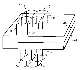
Figure 4 illustrates an arrangement in which
two composite sheet workpieces 40 and 42 are disposed
in facewise engagement and may be reinforced by means
of one or two reinforcing members 20 of the type
created in accordance with the present invention.
Thus, and in this case, the two sheets 40 and 42 are
preforms and the pins on each of the opposed
reinforcing members 20, will be inserted into each of
the preforms to thereby physically hold the same
together. In this respect, it should be understood in
connection with the present invention that the
reinforcing members 20 are highly effective with
preforms. The preform workpieces 40, 42 may be either
CA 02259705 1999-01-20
-12-
in a wet or a dry form. Thus, they may be
pre-impregnated but not cured until the reinforcing
members 20 have been positioned in place. Moreover,
they can be dry and ultimately impregnated when the
reinforcing members 20 have been located in a
reinforcing position.
Figure 6 shows an arrangement in which the
reinforcing members are used to secure the stringers 50
and the web flanges 58 of the intercostals 52 together.
This framework thus provides support for a preform
sheet 54. Figure 6 shows the use of reinforcing
members 20 in accordance with the present invention
being secured to a web flange 58 of the intercostal 52
and into the web 60 of the respective stringer 50.
Although not specifically shown in Figure 6, additional
reinforcing members could be used for securing the base
flange 56 of the stringers 50 to the sheet 54 to obtain
extra localized strength properties. In addition, the
joints between the various components may have been
stitched, to the extent practicable, prior to the
application of the reinforcing members 20 of the
present invention to compact the respective preforms.
When using the reinforcing members 20 of the
invention, the pins 12 are inserted into the relatively
soft preform material and then all of the components
are subjected to curing as, for example, by heating.
As this occurs, the resin impregnated into the preform
workpiece and into or around the pins and the grid of
the reinforcing member will cause a fusing or bonding
of the reinforcing member to the preform and become an
integral part of the structure.
Figure 7 shows an overall step procedure of
making and installing the 3-D grid into a preform and
final resin impregnation and cure to make the desired
enhanced damage-tolerant structure. Thus, there has
been illustrated and described a unique and novel
method of making and applying a 3-D grid reinforced
CA 02259705 1999-01-20
-13-
plastic composite reinforcing member which thereby
fulfills all of the objects and advantages which have
been sought.
It should be understood that many changes,
modifications, variations and other uses and
applications will become apparent to those skilled in
the art after considering this specification and the
accompanying drawings. Therefore, any and all such
changes, modifications, variations and other uses and
applications which do not depart from the spirit and
scope of the invention are deemed to be covered by the
invention.