Language selection

Search

Patent 2259732 Summary

Third-party information liability

Some of the information on this Web page has been provided by external sources. The Government of Canada is not responsible for the accuracy, reliability or currency of the information supplied by external sources. Users wishing to rely upon this information should consult directly with the source of the information. Content provided by external sources is not subject to official languages, privacy and accessibility requirements.

Claims and Abstract availability

Any discrepancies in the text and image of the Claims and Abstract are due to differing posting times. Text of the Claims and Abstract are posted:

  • At the time the application is open to public inspection;
  • At the time of issue of the patent (grant).
(12) Patent: (11) CA 2259732
(54) English Title: SYNCHRONIZED MAGNETIC STIRRING AND HEATING DEVICE
(54) French Title: DISPOSITIF SYNCHRONISE MAGNETIQUE POUR CHAUFFER ET MELANGER
Status: Deemed expired
Bibliographic Data
(51) International Patent Classification (IPC):
  • B01F 13/08 (2006.01)
  • B01F 13/10 (2006.01)
  • B01L 1/00 (2006.01)
  • G01N 1/38 (2006.01)
  • G01N 1/44 (2006.01)
  • B01F 13/06 (2006.01)
  • B01F 15/00 (2006.01)
  • B01L 7/00 (2006.01)
  • G01N 7/00 (2006.01)
  • G01N 11/14 (2006.01)
(72) Inventors :
  • MORRIS, JOSEPH E., JR. (Canada)
(73) Owners :
  • MORRIS, JOSEPH E., JR. (United States of America)
(71) Applicants :
  • MORRIS, JOSEPH E., JR. (United States of America)
(74) Agent: NA
(74) Associate agent: NA
(45) Issued: 2001-07-17
(22) Filed Date: 1999-01-20
(41) Open to Public Inspection: 2000-07-20
Examination requested: 1999-02-11
Availability of licence: N/A
(25) Language of filing: English

Patent Cooperation Treaty (PCT): No

(30) Application Priority Data: None

Abstracts

English Abstract

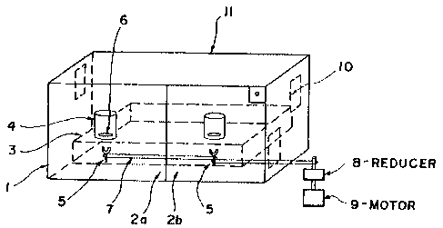
An apparatus for testing a plurality of fluid samples at elevated temperatures and/or pressures, while providing for simultaneous stirring of said samples to simulate desired fluid flow regimes, includes: temperature controlled and insulated enclosure; multiple pressurized fluid sample cells; and means for magnetically stirring multiple fluid samples in a synchronized manner.


French Abstract

Un appareil pour tester une pluralité d'échantillons de liquide à des pressions et/ou températures élevées, tout en fournissant un mélange simultané desdits échantillons pour simuler les régimes d'écoulement de liquide souhaités, comprend : un boîtier isolé et à température contrôlée; plusieurs cellules d'échantillon de liquide pressurisé; et des dispositifs pour mélanger magnétiquement plusieurs échantillons de liquide de manière synchronisée.

Claims

Note: Claims are shown in the official language in which they were submitted.


CLAIMS
What is claimed is the following:
1. A synchronized stirring and heating test apparatus comprising:
a. a heated and thermally insulated enclosure having a base;
b. a stirrer compartment having an upper surface and a lower surface dispose
within said
enclosure;
c. a plurality of stirring shaft assemblies having a top and a bottom end,
wherein the bottom
end of said stirring shaft assemblies are rotatably mounted to the base of
said enclosure
and the top end of said stirring shaft assemblies are magnetically charged and
positioned
proximate to the lower surface of said stirrer compartment;
d. one or more pressurized test cells received on the upper surface of said
stirrer
compartment;
e. magnetic stir bars disposed within said pressurized test cells;
f. a plurality of drive belts affixed to said stirring shaft assemblies; and
g. a motor affixed to said drive belts.
2. The synchronized stirring and heating test apparatus of claim 1, further
comprising a reducer
affixed to at least one of said drive belts.

Description

Note: Descriptions are shown in the official language in which they were submitted.


CA 02259732 2001-O1-24
SYNCHRONIZED MAGNETIC STIRRING ANL> HEATING DEVICE
INVENTOR: Joseph E. Morris, Jr.
BACKGROUND OF THE INVENTION
I. FIELD OF THE INVENTION
The present invention relates to an apparatus for testing a plurality of fluid
samples at elevated
temperatures and/or pressures, while providing for simultaneous stirring of
said samples to simulate
desired fluid flow regimes. More specifically, the present invention relates
to temperature controlled
enclosure containing multiple synchronized magnetic stirring assemblies which
allow for
synchronized stirring and simultaneous thermostating of one or more
pressurized sample cells
containing fluid samples to be tested.
2. DESCRIPTION OF RELATED ART
Stirring apparatuses have been known in the art for some tune. One recent
example is disclosed
in U.S. Pat. No. 5,547,280 to Wanninger et al., which describes a magnetic
stirrer wherein a drive
motor with controlling means and an electrical connection are placed in a
lower part, and a glass
mounting surface, which is largely impervious to aggressive liquids and
vapors, comprises a top part.
Said top part forms a mounting surface for a stirring container which holds a
stirring magnet. The
invention disclosed in Wanninger, et al., is easily distinguishable from the
invention disclosed herein
because is has no means to control the temperature of the samples to be
tested.


CA 02259732 1999-O1-20
An apparatus with a temperature control device is disclosed in U.S. Pat. No.
4,876,069 to
Jochimsen. The Jochimsen patent discloses a blood clotting time measuring
apparatus having a
temperature controlled cabinet with at least one measuring port for receiving
sample cells
containing blood. A magnetic stirrer is mounted in the cabinet proximate to
the measuring port
to enable stirring of a metal ball placed inside the sample cell. However,
unlike the invention
disclosed herein, the Jochimsen patent does not disclose means for enclosing
the entire sample to
be tested. Furthermore, the Jochimsen patent does not disclose means to
analyze the subject
sample at elevated pressures, and envisions use of relatively small-volume
samples.
Another magnetic stirring device with a temperature control mechanism is
disclosed in
U.S. Pat. No. 5,529,391 to Kindman, et al. The invention disclosed in Kindman
relates to a
magnetic stirring and heating/cooling apparatus that provides simultaneous
stirring and
thermostating of multiple, yet relatively small, biological samples. The
apparatus disclosed in
Kindman utilizes a heat conducting block which provides thermostatic
temperature control.
Liquid samples contained in vessels can be inserted into multiple sample wells
which are bored
into said heat conducting block. Multiple coils surround the lower portion of
each of the
multiple sample wells to provide rotating magnetic fields that motivate
magnetic stirring bars
which are positioned inside the sample vessels. Unlike the invention disclosed
herein, the
Kindman patent does not disclose means for applying pressure to the samples
being tested.
Other patents of interest which disclose magnetic stirrers include U. S. Pat.
No. 3,784,170
to Petersen et al.; U.S. Pat. No. 4,991,973 to Maaz et al.; U.S. Pat. No.
4,752,138 to Rufer; U.S.
5i1
Pat. No. 4,759,635 to MacMichael et al.; and U.S. Pat. No. 4,830,1' to Smazik.
However, none
of these references disclose applicant's novel inventive apparatus which
provides for
0126678.01


CA 02259732 1999-O1-20
simultaneous synchronized stirring and thermostating of multiple samples
contained in
pressurized sample cells.
SL>MMARY OF THE INVENTION
With the present invention, applicant provides an apparatus comprising a
temperature
controlled thermal enclosure containing a test surface for receiving a
plurality of pressurized
sample cells containing magnetic stir bars and fluid samples to be tested.
Said test surface is
positioned above multiple magnetic stirring shaft assemblies. Synchronized
rotation of said
synchronized stirring shaft assemblies results in synchronized rotation of
said magnetic stir bars
contained within said pressurized sample cells, which in turn results in
synchronized stirring of
the samples to be tested.
The thermal enclosure is heated and insulated to control temperatures above
ambient
conditions. Although other means of applying heat to the samples may be
contemplated, the heat
source within the enclosure can be providzd by one or more heating elements
mounted on the
internal walls of said enclosure. A temperature control deuce controls the
heating elements to
precisely maintain the temperature within the enclosure at desired levels.
The multiple magnetic stirring shaft assemblies extend to a point proximate to
the base of
the test surface. The multiple magnetic stirring shaft assemblies are
connected, either directly or
indirectly, to provide synchronized rotation of said shafts and magnets, which
in turn rotate, in
synchronized fashion, the magnetic stirring bars present within the
pressurized sample cells.
Although other means of connecting said magnetic stirring shafts may be
contemplated, said
stirring shafts can be connected by belt assemblies. Said belt assemblies are
driven by a motor
equipped with a variable speed control. By adjusting the speed of said motor,
the operator can
0126678.01


CA 02259732 1999-O1-20
adjust the rotational speed of said magnetic stirring shaft assemblies and,
thus, the stirring speed
of the magnetic stir bars contained within the sample cells.
The synchronized stirring and heating test apparatus of the present invention
is designed
to allow for testing of multiple fluid samples at elevated temperatures and
pressures. However,
by adjusting the stirring speed of said magnetic stir bars, the apparatus can
accommodate a wide
range of characteristic fluid flow regimes (e.g. laminar, slug, turbulent,
etc.) The test apparatus
of the present invention is further designed to accommodate pressurized test
cells which can
accept electrochemical probes and inert, electrically neutral, metal coupon
extensions to permit
simultaneous gravimetric studies.
In its preferred embodiment, the synchronized stirring and heating test
apparatus can
accommodate the testing of multiple large or small-volume samples having a
wide range of
viscosities. Furthermore, the entire apparatus is designed to be both fire and
explosion proof.
The test apparatus contains no combustible internal or external components,
and can be fitted
with thermal resistant cable connections.
BRIEF DESCRIPTION OF THE DRAWINGS
Figure 1 is a perspective review of a synchronized stirring and heating test
apparatus in
accordance with the present invention.
DESCRIPTION OF THE PREFERRED EMBODIMENTS
Referring now to Figure 1, the synchronized stirring and heating test
apparatus of the
invention is shown and generally designated 11. The synchronized stirring and
heating test
apparatus 11 comprises an external oven compartment 1 which is lined with
insulating material
0126678.01


CA 02259732 1999-O1-20
for precise temperature control inside the compartment. The external oven
compartment 1 has
doors 2a and 2b for internal access.
The external oven compartment 1 contains a stirrer compartment 3 with an upper
sample
surface designed to support multiple pressurized test cell 4. Said stirrer
compartment 3 is
constructed of non-magnetic, heat and corrosion resistant material, and rests
on support legs to
provides clearance for multiple magnetic stirring shaft assemblies 5. The size
of the stirrer
compartment 3 is such that it can be easily moved in and out of the oven
compartment 1. Stirrer
compartment 3 is positioned so that magnetic stirring shaft assemblies 5 do
not impede stirrer
compartment 3 from being moved in and out of oven compartment 1. Multiple
pressurized test
cells 4 are received on stirrer compartment 3 proximate, to magnetic stirring
shaft assemblies 5.
Each pressurized test cel. 4 contains magnetic stir bar 6.
Magnetic stirring shaft assemblies 5 comprise multiple magnetic stirring
shafts that
extend vertically beneath the sample surface of said rectangular stirrer
compartment 3. The
lower ends of said magnetic stirring shaft assemblies are mounted in bearing
assemblies for
stability and ease of rotation. The top ends of said magnetic stirring shafts
are coupled with
magnets and extend to a point immediately proximate to the lower surface of
the stirrer
compartment 3.
Each magnetic stirring shaft assembly 5 has at least one drive belt 7
connected to its
shaft. Reducer 8 and motor 9 are secured to a side of external oven
compartment 1, and
connected to drive belt 7. A suitable power supply is wired into the motor 9.
Motor 9 is further
equipped with a variable speed control mechanism to provide a means for
varying the level of
stirring within the pressurized sample containers.
0126678.01


CA 02259732 1999-O1-20
Heating elements 10 are secured to internal sides of the oven compartment 1 so
as to heat
the inside of the oven compartment 1 above ambient temperature as desired. A
temperature
sensing probe is utilized to control the temperature inside of oven
compartment 1 at desired
temperatures.
During operation of the synchronized stirring and heating apparatus, motor 9
is activated
to turn at a desired speed. Motor 9 causes rotation, via drive belts 7, of
multiple magnetic
stirring shafts 5. Rotation of said multiple magnetic stirring shafts 5 causes
synchronized
rotation of magnetic stir bars 6 within test cells 4, resulting in
synchronized stirring of fluid
samples contained within test cells 4.
It is understood that various details of the invention may be changed without
departing
from the scope of the invention. Furthermore, the foregoing description is for
the purpose of
illustration only, and not for the purpose of limitation -- the invention
being defined by the
claims.
otzss~s.o1

Representative Drawing
A single figure which represents the drawing illustrating the invention.
Administrative Status

For a clearer understanding of the status of the application/patent presented on this page, the site Disclaimer , as well as the definitions for Patent , Administrative Status , Maintenance Fee  and Payment History  should be consulted.

Administrative Status

Title Date
Forecasted Issue Date 2001-07-17
(22) Filed 1999-01-20
Examination Requested 1999-02-11
(41) Open to Public Inspection 2000-07-20
(45) Issued 2001-07-17
Deemed Expired 2019-01-21

Abandonment History

Abandonment Date Reason Reinstatement Date
2001-01-22 FAILURE TO PAY APPLICATION MAINTENANCE FEE 2001-02-07

Payment History

Fee Type Anniversary Year Due Date Amount Paid Paid Date
Application Fee $150.00 1999-01-20
Request for Examination $200.00 1999-02-11
Advance an application for a patent out of its routine order $100.00 2000-09-29
Reinstatement: Failure to Pay Application Maintenance Fees $200.00 2001-02-07
Maintenance Fee - Application - New Act 2 2001-01-22 $50.00 2001-02-07
Final Fee $150.00 2001-04-09
Maintenance Fee - Patent - New Act 3 2002-01-21 $50.00 2001-12-10
Maintenance Fee - Patent - New Act 4 2003-01-20 $50.00 2002-12-23
Maintenance Fee - Patent - New Act 5 2004-01-20 $75.00 2003-12-02
Maintenance Fee - Patent - New Act 6 2005-01-20 $100.00 2004-12-24
Maintenance Fee - Patent - New Act 7 2006-01-20 $100.00 2005-12-28
Maintenance Fee - Patent - New Act 8 2007-01-22 $100.00 2006-12-20
Maintenance Fee - Patent - New Act 9 2008-01-21 $100.00 2007-12-24
Maintenance Fee - Patent - New Act 10 2009-01-20 $125.00 2009-01-12
Maintenance Fee - Patent - New Act 11 2010-01-20 $125.00 2009-11-23
Maintenance Fee - Patent - New Act 12 2011-01-20 $125.00 2010-12-17
Maintenance Fee - Patent - New Act 13 2012-01-20 $125.00 2011-12-13
Maintenance Fee - Patent - New Act 14 2013-01-21 $125.00 2013-01-16
Maintenance Fee - Patent - New Act 15 2014-01-20 $225.00 2014-01-15
Maintenance Fee - Patent - New Act 16 2015-01-20 $225.00 2015-01-13
Maintenance Fee - Patent - New Act 17 2016-01-20 $225.00 2016-01-20
Maintenance Fee - Patent - New Act 18 2017-01-20 $425.00 2017-02-01
Owners on Record

Note: Records showing the ownership history in alphabetical order.

Current Owners on Record
MORRIS, JOSEPH E., JR.
Past Owners on Record
None
Past Owners that do not appear in the "Owners on Record" listing will appear in other documentation within the application.
Documents

To view selected files, please enter reCAPTCHA code :


To view images, click a link in the Document Description column. To download the documents, select one or more checkboxes in the first column and then click the "Download Selected in PDF format (Zip Archive)" or the "Download Selected as Single PDF" button.

List of published and non-published patent-specific documents on the CPD .

If you have any difficulty accessing content, you can call the Client Service Centre at 1-866-997-1936 or send them an e-mail at CIPO Client Service Centre.


Document
Description 
Date
(yyyy-mm-dd) 
Number of pages   Size of Image (KB) 
Representative Drawing 2000-07-18 1 7
Claims 1999-01-20 1 27
Abstract 1999-01-20 1 12
Description 1999-01-20 6 232
Drawings 1999-01-20 1 11
Cover Page 2001-07-09 1 29
Representative Drawing 2001-07-09 1 8
Cover Page 2000-07-18 1 27
Claims 2001-01-24 1 23
Description 2001-01-24 6 230
Correspondence 2000-11-02 1 1
Prosecution-Amendment 2000-11-06 3 128
Prosecution-Amendment 2000-12-06 49 1,620
Fees 2006-12-20 2 96
Correspondence 1999-02-11 2 74
Correspondence 2000-07-18 1 32
Correspondence 2000-08-17 1 1
Prosecution-Amendment 2000-09-29 1 30
Prosecution-Amendment 2000-10-10 1 1
Prosecution-Amendment 2001-01-24 4 105
Prosecution-Amendment 1999-02-11 1 31
Assignment 1999-01-20 3 107
Prosecution-Amendment 1999-05-27 2 83
Fees 2002-12-23 3 100
Fees 2003-12-02 3 92
Correspondence 2001-04-09 1 89
Assignment 1999-01-20 2 67
Fees 2001-12-10 1 73
Fees 2001-02-07 1 28
Fees 2004-12-24 2 121
Fees 2005-12-28 1 61
Fees 2007-12-24 3 264
Fees 2009-01-12 2 274
Fees 2009-11-23 2 234
Fees 2010-12-17 1 239
Fees 2011-12-13 1 239
Correspondence 2011-12-13 2 262
Fees 2013-01-16 1 131
Fees 2014-01-15 1 125
Fees 2015-01-13 1 24
Maintenance Fee Payment 2016-01-20 2 94
Maintenance Fee Payment 2017-01-27 1 26
Maintenance Fee Payment 2017-02-01 1 27
Office Letter 2017-03-20 1 27
Maintenance Fee Correspondence 2017-02-03 1 16