Note: Descriptions are shown in the official language in which they were submitted.
CA 02259794 1999-03-17
TITLE OF THE INVENTION
PERMANENT MAGNET TYPE ELECTRICAL ROTATING MACHINE
BACKGROUND OF THE INVENTION
1. Field of the Invention
The present invention relates to permanent magnet type
electrical rotating machines, and more particularly to
permanent magnetic type electrical rotating machines in which
the construction of the stators is improved in order to
prevent reduction of the properties of the permanent magnets
that are the rotors.
2. Description of the Related Art
FIG.1 is a partial cross-section view, in a direction
orthogonal to the axis, showing an example of a prior art
permanent magnet type electrical rotating machine. FIG.2 is
an enlarged development view of part C of FIG.1.
In FIG.1 and FIG.2, slots 3F are formed at equal
intervals on the inner periphery of stator core 2H that is
formed in a cylindrical shape by laying silicon steel punched
plates one on another. Stator winding 4B is inserted into
these slots 3F in two layers. Trapezoidal wedges 11,
fabricated of magnetic material described later, are press-
., ,...,, . , .
..,_ .....,w.,...~._...~.nu_ ._ __...._~ _~.:.:..~ __, _ _
CA 02259794 1999-03-17
fitted into the inner periphery sides of slots 3F. Tooth-
like parts lOB of the stator core are formed between slots 3F.
Wedges 11 are made of hardened material by mixing
malleable iron powder with resin and a reinforcing agent to
become high-resistance magnetic material with a relative
magnetic permeability ( ) of about 10 -100.
At the same time, permanent magnets 6 of arc-shaped
cross-section are mounted in close contact with the outer
periphery of rotor core 7 in the peripheral direction and
bonded with an adhesive agent to form rotor S. Magnets
magnetized with S poles on the inner periphery side and N
poles on the outer periphery side are mounted alternately
with magnets magnetized with the reverse polarity, according
to the number of poles.
Prevention of the peeling-off of permanent magnets 6
due to the centrifugal force generated by high-speed rotation
is designed by press-fitting cylindrical retaining ring 8 on
the outer peripheries of these permanent magnets 6.
Specified gap 9 is formed between the outer periphery of
retaining ring 8 and inner periphery of stator core 2H.
In a permanent magnet type electrical rotating machine
constructed in this way, magnetic flux 13 emanating from the
outer periphery side of permanent magnets 6 reaches the outer
periphery side of stator core 2H from wedges 11 and tooth-
like parts 10B between these wedges 11 after passing through
retaining ring 8 and gap 9, as shown in FIG.2. From this
2
CA 02259794 1999-03-17
outer periphery side, the flux once more passes through a
magnetic path via the neighbouring permanent magnet poles.
This permanent magnetic type electrical rotating
machine is driven in rotation at high speed by increasing the
frequency of the inverter power source that excites stator
winding 4B.
FIG.3 is a drawing corresponding to FIG.2, and is an
enlarged partial development illustration showing the
magnetic flux distribution emanating from a permanent magnet
for the case when non-magnetic wedges 12 are used in place of
magnetic material wedges 11.
In FIG.3, the point of difference from above-mentioned
FIG.2 is that the greater part of magnetic flux 13 emanating
from permanent magnets 6 passes through tooth-like parts 10B
of stator core 2H while hardly any passes through non-
magnetic wedges 12.
That is to say, hardly any flux passes through the
inner periphery side of stator winding 4B, but is
concentrated in the trapezoidal parts of the inner periphery
sides of tooth-like parts 10.
Consequently, the peaks of the sine wave of the
magnetic flux passing between permanent magnets 6 and the
stator oscillate as shown in FIG.4(a), and therefore the
rotor torque oscillates.
On the other hand, with a permanent magnet type
electrical rotating machine that incorporates magnetic
3
CA 02259794 1999-03-17
material wedges 11 shown in FIG.2, eddy currents flow in
wedges 11 due to the magnetic flux passing through wedges 11.
Thus, not only does the temperature of wedges 11 rise, but
since, as mentioned above wedges 11 are made of hardened
material , wedges 11 are very brittle, extreme care is
required in their manufacture and assembly processes.
Moreover, eddy currents also flow in retaining ring 8
due to the magnetic flux passing through retaining ring 8.
Since permanent magnets 6 are heated when the temperature of
retaining ring 8 rises, the magnetic properties (coercive
force) of permanent magnets 6 reduce.
SZJNIlKARY OF THE INVENTION
Accordingly, one object of the present invention is to
provide a novel permanent magnet type electrical rotating
machine that may prevent the reduction in the permanent
magnet properties consequent upon the temperature rise of the
retaining ring, and may also solve the problem of wedge
damage.
In order to achieve the above object, in a permanent
magnet type electrical rotating machine of the present
invention, in opposition to the inner part of a cylindrical
stator, in which multiple enclosed slots that form
projecting parts on the shaft center side of their stator
winding insertion parts are formed radially at equal
4
CA 02259794 1999-03-17
intervals, a rotor, on the outer periphery of which multiple
permanent magnets with their polarities reversed in the
radial direction are closely mounted, is inserted on the same
shaft, and a cylindrical retaining ring is closely inserted
on the outer periphery of this rotor.
Also, in order to achieve the above object, in a
permanent magnet type electrical rotating machine of the
present invention, the stator winding is composed of U-shaped
wire bundles of rectangular cross-section, and the open ends
of the U-shapes are connected.
Moreover, in order to achieve the above object, in a
permanent magnet type electrical rotating machine of the
present invention, the stator is divided into two at the
shaft center side, or the outer periphery side, of the stator
winding.
Furthermore, in order to achieve the above object, in
a permanent magnet type electrical rotating machine of the
present invention, the shapes of the inner periphery of the
outer stator and the outer periphery of the inner stator of a
stator that is divided into two at the outer periphery side
of the stator winding are formed as ellipses.
Still further, in order to achieve the above object,
in a permanent magnet type electrical rotating machine of the
present invention, the shapes of the inner periphery of the
outer stator and the outer periphery of the inner stator of a
stator that is divided into two at the outer periphery side
5
CA 02259794 1999-03-17
of the stator winding are formed as circles having straight
line parts in at least one place.
Again, in order to achieve the above object, in a
permanent magnet type electrical rotating machine of the
present invention, the shapes of the inner periphery of the
outer stator and the outer periphery of the inner stator of a
stator that is divided into two at the outer periphery side
of the stator winding are formed in shapes from pentagons to
polygons with the same number of angles as the number of
stator coils.
Yet again, in order to achieve the above object, in a
permanent magnet type electrical rotating machine of the
present invention, the heat intake sides of heat pipes are
installed in the projecting parts formed in the above-
mentioned enclosed slots of the stator.
Also, in order to achieve the above object, in a
permanent magnet type electrical rotating machine of the
present invention, detector coils that detect the angle of
rotation of the rotor are installed in the projecting parts
formed in the enclosed slots of the stator.
Moreover, in order to achieve the above object, in a
permanent magnet type electrical rotating machine of the
present invention, vibration suppression coils, through which
a current corresponding to the rotor vibration is passed and
that suppress the vibration of the rotor, are installed in
the projecting parts formed in the enclosed slots of the
6
CA 02259794 1999-03-17
stator.
Furthermore, in order to achieve the above object, in
a permanent magnet type electrical rotating machine of the
present invention, projecting parts, against which the outer
peripheries of the stator coils butt, are formed on the inner
periphery of the outer stator that has been divided into two
at the outer periphery side of the stator winding, and the
outer periphery sides of the tooth-like parts of the inner
stator interlock with these projecting parts.
Still further, in order to achieve the above object,
in a permanent magnet type electrical rotating machine of the
present invention, non-magnetic rear wedges are installed in
outer periphery sides of the slots of the inner stator that
is divided into two at the outer periphery side of the stator
winding.
Again, in order to achieve the above object, in a
permanent magnet type electrical rotating machine of the
present invention, the permanent magnet type electrical
rotating machine is made a super-high speed permanent magnet
type electrical rotating machine.
By these means, with the present invention, the
retaining ring and the inner periphery of the stator are set
in continual magnetic opposition one against the other. Thus,
oscillation of the magnetic flux distribution in the
peripheral direction between this retaining ring and the
stator is prevented, oscillation of the torque caused by this
7
CA 02259794 2006-08-23
29606-5
oscillation and the temperature rise due to eddy currents in
the retaining ring are suppressed, and reduction of the
properties of the permanent magnets is prevented.
According to another aspect, there is provided a
permanent magnet electrical rotating machine, comprising: a
tube-shaped stator comprising a plurality of enclosed slots
formed radially at equal intervals, a stator winding
disposed in said enclosed slots, and said slots having empty
triangular prism shaped projecting gaps disposed at an inner
periphery side of the enclosed slots to close said enclosed
slots; a rotor which is inserted inside, and co-axially
with, said stator and on an outer periphery of which a
plurality of permanent magnets is closely bonded with radial
direction polarities alternately reversed; and a cylindrical
retaining ring which is closely bonded to said outer
periphery of said rotor.
BRIEF DESCRIPTION OF THE DRAWING
A more complete appreciation of the present
invention and many of the attendant advantages therefor will
be readily obtained as the same becomes better understood by
reference to the following detailed description when
considered in connection with the accompanying drawings,
wherein:
FIG. 1 is a partial longitudinal section view
showing an example of a prior art permanent magnet type
electrical rotating machine;
FIG. 2 is an enlarged developed illustration
showing part C of FIG. 1;
8
CA 02259794 2006-08-23
29606-5
FIG. 3 is an enlarged developed illustration
showing an example of a prior art permanent magnet type
electric motor that differs from FIG. 2;
FIG. 4(a) is a graph showing the working of the
permanent magnet type electrical rotating machine shown in
FIG. 3, while FIG. 4(b) is a graph showing the working of
the permanent magnet type electrical rotating machine shown
in FIG. 2;
FIG. 5 is a longitudinal section showing a first
embodiment of the permanent magnet type electrical rotating
8a
CA 02259794 1999-03-17
machine of the present invention;
FIG.6(a) is an oblique view showing the stator winding
that is assembled into the permanent magnet type electrical
rotating machine shown in FIG.5, while FIG.6(b) is an
enlargement of the cross-section view at B - B in FIG.5(a);
FIG.7 is an enlarged development illustration of part
A of FIG.5;
FIG.8 is a longitudinal section view showing a second
embodiment of the permanent magnet type electrical rotating
machine of the present invention;
FIG.9 is a longitudinal section view showing a third
embodiment of the permanent magnet type electrical rotating
machine of the present invention;
FIG.10 is a longitudinal section view showing a fourth
embodiment of the permanent magnet type electrical rotating
machine of the present invention;
FIG.11 is a longitudinal section view showing a fifth
embodiment of the permanent magnet type electrical rotating
machine of the present invention;
FIG.12 is a longitudinal section view showing a sixth
embodiment of the permanent magnet type electrical rotating
machine of the present invention;
FIG.13(a) is a block diagram showing the operation of
the seventh embodiment of the permanent magnet type
electrical rotating machine of the present invention, while
FIG.13(b) is a block diagram showing the operation of an
9
CA 02259794 1999-03-17
eighth embodiment of the permanent magnet type electrical
rotating machine of the present invention;
FIG.14 is a longitudinal section view showing a ninth
embodiment of the permanent magnet type electrical rotating
machine of the present invention;
FIG.15 is a longitudinal section view showing a tenth
embodiment of the permanent magnet type electrical rotating
machine of the present invention;
FIG.16 is a longitudinal section view showing an
eleventh embodiment of the permanent magnet type electrical
rotating machine of the present invention.
DETAILED DESCRIPTION OF THE PREFERRED EMBODIMENTS
Referring now to the drawings, wherein like reference
numerals designate identical or corresponding parts
throughout the several views, and more particularly to FIG.5
thereof, one embodiment of the present invention will be
described.
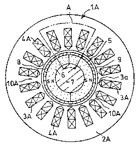
FIG.5 is a longitudinal section view showing a first
embodiment of the permanent magnet type electrical rotating
machine of the present invention, and corresponds to the
prior art technology shown in FIG.1.
Also, FIG.6(a) is an oblique view showing a stator
winding that is assembled into the permanent magnet type
electrical rotating machine shown in FIG.5, while FIG.6(b) is
CA 02259794 1999-03-17
an enlargement of the cross-sectionview at B - B in FIG.5(a).
FIG.7 is an enlarged development illustration of part A of
FIG.5, and corresponds to the prior art technology shown in
FIG.2 and FIG.3.
In FIG.5, FIG.6 and FIG.7, the points of difference
from the prior art technology shown in FIG.1, FIG.2 and FIG.3
are that, in the construction of the stator, the slots formed
in the stator core and the stator winding inserted into these
slots are different.
That is to say, slots 3A punched radially in stator
core 2A do not form openings on the inner periphery side of
stator winding 4A, which is inserted into these slots 3A.
They are enclosed slots in which triangular prism-shaped
projecting parts are formed at the ends on the inner
periphery side.
Also, stator windings 4A that are inserted in slots 3A
are bent into U-shapes, as shown in FIG.6(a), and after
laying wire strands 17 one upon another in a roughly square
shape, as shown in FIG.6(b), outer skin insulation 18 is
completed.
These stator windings 4A are inserted into each slot
3A of stator core 2A from one side in the axial direction.
After connecting wires have been connected to the other ends
by brazing, the connected parts are covered with insulating
tape.
High magnetic permeability neodium = iron = boron
11
CA 02259794 1999-03-17
alloy (Nd-Fe-B alloy) is adopted for permanent magnets 6 on
the outer periphery of rotor 5, and, in FIG.5, rotor 1A has
two poles.
Next, the working of a permanent magnet type
electrical rotating machine constructed in this way will be
described.
Magnetic flux 13, shown in FIG.7, that arrives at
stator core 2A from permanent magnets 6, since no openings
are formed on the inner periphery side of stator core 2A,
passes via the broad opposing surfaces that are the opposing
surfaces of retaining ring 8 and tooth-like parts 10B. This
becomes main magnetic flux 27, almost all of which passes
between stator windings 4A.
That is to say, further to the inner periphery side of
stator winding 4A than the inner periphery sides of
projecting parts 3a, narrow magnetic paths are formed by
projecting parts 3a. Therefore, magnetic flux 20 that leaks
to neighbouring poles by these narrow magnetic paths is small,
and oscillation and reduction of torque may be prevented.
Also, oscillation of the magnetic flux may be prevented, and
magnetic flux distribution in the peripheral direction, such
as shown in FIG.4(b), may be produced. Therefore, the eddy
currents generated in retaining ring 8 may also be suppressed.
Consequently, the magnetic flux oscillation shown in
FIG.4(a), which is generated in the permanent magnet type
electrical rotating machine shown in FIG.3 that uses non-
12
CA 02259794 1999-03-17
magnetic wedges, and the torque oscillation caused by that
oscillation, may be prevented.
At the same time, wire bundles 18 of narrow wire
strands 17 are used in stator winding 4A. Therefore, the
increase of resistance value caused by the skin effect of
high-frequency exciting currents due to high-speed rotation
may be prevented, and temperature rise due to this may be
inhibited.
Moreover, by making projecting parts 3a formed on the
inner periphery sides of slots 3A parts for the percolation
of cooling gas, stator winding 4A, which is the part with the
highest temperature rise, may be cooled. Therefore
deterioration of the insulation layer of stator winding 4A
may be prevented, and its life may be extended. Thus,
inspection and maintenance intervals may also be extended.
Also, torque oscillation may be prevented. Therefore,
not only may speed adjustment times be shortened, but rotor
vibration may be suppressed and bearing fatigue may also be
prevented.
Next, a second embodiment of the permanent magnet type
electrical rotating machine of the present invention will be
described using FIG.8.
In FIG.8, the points of difference from FIG.5 showing
the first embodiment described above are that the structure
of the stator core is a two-division structure of a ring-
shaped inner stator core and an outer stator core that is
13
CA 02259794 1999-03-17
fitted outside this inner stator core. Apart from this, the
remainder is the same as in the first embodiment shown in
FIG.5 - FIG.7. Consequently, like reference numerals have
been assigned to elements that are the same as in FIG.5 -
FIG.7, and their descriptions have been omitted.
That is to say, stator core 2B shown in FIG.7 is
composed of approximately ring-shaped inner stator core 2a,
of which the outer periphery side of stator winding 4B is the
outer periphery, and outer stator core 2b, which is fitted on
the outer periphery of this inner stator core 2a.
Consequently, slots 3B, into which stator winding 4B
is inserted, are open on the outer periphery side of inner
stator core 2a, and stator winding 4B of the same
configuration as the stator winding shown by the prior art
technology of FIG.1 is fitted into them.
The work of fitting outer stator core 2b on inner
stator core 2a is by heating outer stator core 2b by
induction heating and then fitting it on inner stator core 2a
into which stator winding 4B has been inserted. When cooled
to normal temperature, it is in a press-fitted state.
In the running state, since the temperature rise value
of inner stator core 2a is high relative to the temperature
rise value of outer stator core 2b, the clamping force
further increases.
In this case, stator winding 4B that has been produced
with the same external shape as a prior art stator winding is
14
CA 02259794 1999-03-17
incorporated. Thus, there is convertibility of manufacturing
facilities, production is simple, and torque oscillation and
the eddy currents generated in retaining ring 8 may also be
reduced in the same way as with the first embodiment.
Next, FIG.9 is a longitudinal section view showing a
third embodiment of a permanent magnet type electrical
rotating machine of the present invention, and corresponds to
FIG.5 and FIG.8 that show embodiments mentioned above.
In FIG.9, the point of difference from the embodiment
shown in FIG.8 is that, while it has the same stator core
structure and, like FIG.8, is divided into an inner stator
core and an outer stator core, the configurations of those
divided parts differ from FIG.8.
That is to say, with inner stator core 2c of stator
core 2C shown in FIG.9, the outer periphery sides of the
tooth-like parts project slightly further than the face of
the outer periphery side of stator winding 4B. Consequently,
the surfaces of outer stator core 2d that make contact with
the outer periphery of stator winding 4B project further
inward than the outer periphery of inner stator core 2c.
These adjacent parts form interlocking parts 2x, due to their
slight unevenness.
In a permanent magnet type electrical rotating machine
in which stator 1C is composed in this way, by slightly
heating outer stator core 2d, it may be fitted on inner
stator core 2c. After cooling to normal temperature,
CA 02259794 1999-03-17
interlocking parts 2x bind closely together and, when running,
the bonding strength of interlocking parts 2x further
increases due to the heating of inner stator core 2c.
Next, FIG.10 is a longitudinal section view showing a
fourth embodiment of a permanent magnet type electrical
rotating machine of the present invention and corresponds to
FIG.5, FIG.8 and FIG.9 that show embodiments mentioned above.
In FIG.10, the point of difference from the
embodiments shown in FIG.8 and FIG.9 is that, although there
is the same stator core structure, which is divided into an
inner stator core and an outer stator core as in FIG.8 and
FIG.9, the location of that division differs from FIG.8 and
FIG.9.
That is to say, inner stator core 2e and outer stator
core 2f of stator core 2D shown in FIG.10 are divided from
each other at a position on the inner side face of stator
winding 4A. Consequently, triangular prism-shaped gas
passages for cooling are formed in the outer periphery side
of inner stator core 2e.
In a permanent magnet type electrical rotating machine
in which stator 1D is composed in this way, inner stator core
2e may be fitted by slightly heating outer stator core 2f.
After cooling to normal temperature, the interlocked parts
bind closely together and, when running, the bonding strength
of the interlocked parts further increases due to the heating
of inner stator core 2e.
16
CA 02259794 1999-03-17
FIG.11 is a longitudinal section view showing a fifth
embodiment of a permanent magnet type electrical rotating
machine of the present invention, and corresponds to FIG.5
and FIG.8 - FIG.10 that show embodiments mentioned above.
In FIG.11, the point of difference from FIG.5, in
which the above-mentioned first embodiment is shown, is that
the heat-intake sides of heat pipes 14 that use Freon as the
refrigerant, are inserted in the triangular prism-shaped
parts of slots 3A of stator core 2A. The heat-release sides
of these heat-pipes 14 are brazed to the outer frame of the
stator.
In a permanent magnet type electrical rotating machine
constructed in this way, the heat from the inner periphery
side of stator winding 4A, which is the part with the highest
temperature rise, is absorbed by the heat-intake sides of
heat-pipes 14. The refrigerant, which has been gasified as a
result, is condensed in the heat-release sides on the outer
frame side and, after liquefaction, is caused to flow back to
the heat-intake parts and cools stator winding 4A a second
time. Thereafter, by repeating this, the insulating
properties of the insulation layer of stator winding 4A,
which determines the life and rated current of this
electrical rotating machine, will be maintained.
Consequently, not only may reduction of the properties
of the permanent magnets caused by the temperature rise of
retaining ring 8 be prevented, but the conducting capacity of
17
CA 02259794 1999-03-17
this permanent magnet type electrical rotating machine may be
further increased, and its life may also be extended.
FIG.12 is a longitudinal section view showing a sixth
embodiment of a permanent magnet type electrical rotating
machine of the present invention, and corresponds to the
above-mentioned FIG.5 and FIG.8 - FIG.11.
In FIG.12, the point of difference from FIG.11 is that
auxiliary winding 15 is inserted into the projecting parts of
slots 3A of stator core 2A, instead of heat pipes 14 shown in
FIG.11. The remainder is the same as in FIG.11.
In a permanent magnet type electrical rotating machine
constructed in this way, the voltage induced in auxiliary
winding 15 by the magnetic fields of permanent magnets 6 as
the rotor rotates is inputted to separately-located rotor
magnetic pole position calculator 21, as shown in FIG.13(a).
Thus, the magnetic pole positions of permanent magnets 6 are
detected.
This detection signal is inputted to separately-
located inverter control device 22. A frequency is inputted
to controlled inverter 23 by being ON/OFF controlled by the
driving signal of inverter control device 22. The electric
power of the frequency outputted from inverter 23 controls
the speed of rotation of the rotor by being supplied to
stator winding 4A.
Consequently, in a permanent magnet type electrical
rotating machine constructed in this way, the unillustrated
18
CA 02259794 1999-03-17
magnetic pole position detectors that, in prior art, were
fitted on the end of the rotor shaft and the end of the
stator casing may be eliminated. Therefore, the axial
direction length of this electrical rotating machine may be
shortened, and the inertia of the rotating parts may also be
reduced. Thus, high-speed rotation becomes even more simple.
FIG.13(b) is a block diagram showing a seventh
embodiment of a permanent magnet type electrical rotating
machine of the present invention, and corresponds to
FIG.13(a).
With this embodiment, the detection signal of the
rotor vibration that is generated by high-speed rotation is
inputted to rotor displacement calculator 24 that calculates
rotor displacement. The result of calculation by rotor
displacement calculator 24 is inputted to inverter control
device 22 and is amplified by amplifier 25 incorporated in
inverter control device 22. After this, the amplified
electric power excites auxiliary winding 15, and the
vibration that causes shaft-deviation is suppressed by the
electro-magnetic power of the magnetic flux generated by
auxiliary winding 15.
Incidentally, the details of the operation at this
time are described in a previous Application (Patent
Application Heisei 9-180840).
Consequently, the rated maximum speed of rotation may
be increased, and reduction of life due to vibration may be
19
CA 02259794 1999-03-17
inhibited.
Next, an eighth embodiment of a permanent magnet type
electrical rotating machine of the present invention will be
described using FIG.14.
The point in which FIG.14 differs from the above-
mentioned second embodiment shown in FIG.8 is in the two-
division structure of the rotor core. The remainder is the
same as in the second embodiment shown in FIG.8.
Consequently, like reference numerals have been assigned to
elements that are the same as in FIG.8, and their
descriptions have been omitted.
That is to say, stator core 2E shown in FIG.14 is
composed of annular inner stator core 2g, of which the
external diameters are, in the left to right direction a
short diameter and in the front to back direction a long
diameter, and outer stator core 2h, which is fitted to the
outer periphery of inner stator core 2g. The reason for
adopting this configuration is to prevent inner stator core
2g trying to turn under the turning force (torque) that is
generated in inner stator core 2g as the rotor rotates.
Consequently, the slots into which stator winding 4B
is inserted are shallow slots 3B on the short diameter side
and deep slots 3E on the long diameter side. Stator winding
4B, of the same configuration as the stator winding shown in
the prior art technology of FIG.1, is incorporated in the
same way as in FIG.8.
CA 02259794 1999-03-17
For the work of fitting together outer stator core 2h
and inner stator core 2g, outer stator core 2h is heated by
induction heating and then fitted to inner stator core 2g,
into which stator winding 4B has been inserted. When it has
been cooled to room temperature, the stator core is in a
press-fitted state.
In the running state, since the temperature rise value
of inner stator core 2g is higher than the temperature rise
value of outer stator core 2h, the clamping force further
increases.
In this case also, stator winding 4B that has been
produced with the same external shape as a prior art stator
winding is incorporated. Thus, there is convertibility of
manufacturing facilities, production is simple, and torque
oscillation and the eddy currents generated in retaining ring
8 may also be reduced in the same way as with the first
embodiment.
Next, FIG.15 is a longitudinal section view showing a
ninth embodiment of a permanent magnet type electrical
rotating machine of the present invention, and corresponds to
FIG.5, FIG.8, FIG.9 and FIG.14 that show above-mentioned
embodiments.
In FIG.15, the point of difference from the embodiment
shown in FIG.14 is that, although the stator core structure
is similar and is divided into an inner stator core and an
outer stator core in the same way as in FIG.14, the
21
CA 02259794 1999-03-17
configurations of those divisions differ.
That is to say, stator core 2F shown in FIG.15 is
composed of inner stator core 2j and outer stator core 2k.
Parallel faces that fit closely together are formed in the
outer periphery of inner stator core 2j and in the inner
periphery of outer stator core 2k.
In the same way as in FIG.14 above, non-magnetic rear
wedges 16 are inserted into the slots formed in the outer
periphery of inner stator core 2j.
In a permanent magnet type electrical rotating machine
in which stator 1C is composed in this way, by slightly
heating outer stator core 2k it may be fitted on inner stator
core 2j and, after cooling to normal temperature, the
interlocked parts will bind closely together. When running,
the bonding strength of the interlocked parts further
increases due to heating of inner stator core 2j.
Next, FIG.16 is a longitudinal section view showing a
tenth embodiment of a permanent magnet type electrical
rotating machine of the present invention, and corresponds to
FIG.5, FIG.8, FIG.9, FIG.14 and FIG.15 showing above-
mentioned embodiments.
In FIG.16, the point of difference from the embodiment
shown in FIG.9 is that, although the stator core structure is
similar and is divided into an inner stator core and an outer
stator core at the outer peripheries of the slots part in the
same way as in FIG.9, the configuration of that division is,
22
CA 02259794 1999-03-17
overall, a polygonal shape, being a series of short straight
lines as opposed to the series of short arcs in FIG.9.
That is to say, stator core 2G, shown in FIG.16 is
composed by the interlocking of inner stator core 2m and
outer stator core 2n, and also in FIG.16, there is a regular
18-angled polygon (octadecagon) with the same number of
angles as there are stator windings 4B.
In a permanent magnet type electrical rotating machine
in which stator 1J is constructed in this way, by slightly
heating outer stator core 2n, inner stator core 2m may be
inserted into it. After cooling to normal temperature, the
interlocking parts will bind closely together. When running,
the bonding strength of the interlocking parts will further
increase due to heating of inner stator core 2m.
Incidentally, heat pipes 14 shown in FIG.11 or the
auxiliary coils shown in FIG.12 may also be inserted in the
slots of the embodiments shown in FIG.15 - FIG.16. Thus,
improvement in the cooling effect or further increase of
speed through reducing inertia and vibration by shortening of
the rotor may be designed.
When using the present invention, a rotor, in which a
plurality of permanent magnets with polarities alternately
reversed in the radial direction are closely bonded to its
outer periphery, is inserted on the same shaft as a tube-like
stator, in which a plurality of enclosed slots that form
projecting parts on the axial side of the stator coil
23
CA 02259794 1999-03-17
insertion parts are formed radially at equal intervals. By
inserting and tightly bonding a cylindrical retaining ring on
the outer periphery of this rotor, continual magnetic
opposition is set between the retaining ring and the inner
periphery of the stator. Thus, oscillation of the magnetic
flux distribution in the periphery direction between this
retaining ring and the rotor is prevented; the torque
oscillation and retaining ring eddy currents caused by this
magnetic oscillation are suppressed; and reduction of the
permanent magnet properties is also prevented. Therefore it
is possible to obtain a permanent magnet type electrical
rotating machine that may prevent the reduction of the
permanent magnet properties that accompanies temperature rise
of the retaining ring.
In particular, when using the present invention, the
influence of skin-effect during high-speed rotation is
reduced by composing the stator coils by rectangular cross-
section wire bundles of wire strands formed in U-shapes, and
connecting the open ends of the U-shapes. Also, when using
the present invention, incorporation of the stator winding is
simplified by dividing the stator into two on the axial side
or the outer periphery side of the stator winding, and
continual magnetic opposition is set between the retaining
ring and the inner periphery of the stator. Thus,
oscillation of the magnetic flux distribution in the
periphery direction between this retaining ring and the rotor
24
CA 02259794 1999-03-17
is prevented; the torque oscillation and retaining ring eddy
currents caused by this magnetic oscillation are suppressed;
and reduction of the permanent magnet properties is also
prevented. Therefore it is possible to obtain a permanent
magnet type electrical rotating machine that may prevent the
reduction of the permanent magnet properties that accompanies
temperature rise of the retaining ring, and may solve the
problem of wedge damage.
Moreover, when using the present invention, the shapes
of the inner periphery of the outer stator and the outer
periphery of the inner stator, of the stator that is divided
into two at the outer periphery of the stator winding, are
made elliptical. Furthermore, when using the present
invention, assembly is simple and mutual slippage during
rotation is prevented by making the shapes of the inner
periphery of the outer stator and the outer periphery of the
inner stator, of a stator that is divided into two at the
outer periphery of the stator winding, circles provided with
straight lines in at least one place. At the same time, by
setting continual magnetic opposition between the retaining
ring and the inner periphery of the stator, oscillation of
the magnetic flux distribution in the periphery direction
between this retaining ring and the rotor is prevented; the
torque oscillation and retaining ring eddy currents caused by
this magnetic oscillation are suppressed; and reduction of
the permanent magnet properties is also prevented. Therefore
CA 02259794 1999-03-17
it is possible to obtain a permanent magnet type electrical
rotating machine that may prevent the reduction of the
permanent magnet properties that accompanies temperature rise
of the retaining ring, and may solve the problem of wedge
damage.
Also, when using the present invention, mutual
slippage during rotation is prevented by making the shapes of
the inner periphery of the outer stator and the outer
periphery of the inner stator, of a stator that is divided
into two at the outer periphery of the stator winding, any
shape from pentagons to polygons with the same number of
angles as the number of stator coils. At the same time, by
setting continual magnetic opposition between the retaining
ring and the inner periphery of the stator, oscillation of
the magnetic flux distribution in the periphery direction
between this retaining ring and the rotor is prevented; the
torque oscillation and retaining ring eddy currents caused by
this magnetic oscillation are suppressed; and reduction of
the permanent magnet properties is also prevented. Therefore
it is possible to obtain a permanent magnet type electrical
rotating machine that may prevent the reduction of the
permanent magnet properties that accompanies temperature rise
of the retaining ring, and may solve the problem of wedge
damage.
Moreover, when using the present invention, the heat-
intake sides of heat pipes are inserted in the projecting
26
CA 02259794 1999-03-17
parts formed in the enclosed slots of the stator, thus
inhibiting any temperature rise of the stator winding.
Furthermore, when using the present invention, the shaft
length of the rotor is decreased by inserting detector coils,
that detect the angle of rotation of the rotor, into the
projecting parts formed in the enclosed slots of the stator.
At the same time, by setting continual magnetic opposition
between the retaining ring and the inner periphery of the
stator, oscillation of the magnetic flux distribution in the
periphery direction between this retaining ring and the rotor
is prevented; the torque oscillation and retaining ring eddy
currents caused by this magnetic oscillation are suppressed;
and reduction of the permanent magnet properties is also
prevented. Therefore it is possible to obtain a permanent
magnet type electrical rotating machine that may prevent the
reduction of the permanent magnet properties that accompanies
temperature rise of the retaining ring, and may solve the
problem of wedge damage.
Also, when using the present invention, vibration is
suppressed by inserting vibration suppressor coils, that
suppress vibration by passing currents corresponding to the
vibration of the rotor, into the projecting parts formed in
the enclosed slots of the stator. At the same time, by
setting continual magnetic opposition between the retaining
ring and the inner periphery of the stator, oscillation of
the magnetic flux distribution in the periphery direction
27
CA 02259794 1999-03-17
between this retaining ring and the rotor is prevented; the
torque oscillation and retaining ring eddy currents caused by
this magnetic oscillation are suppressed; and reduction of
the permanent magnet properties is also prevented. Therefore
it is possible to obtain a permanent magnet type electrical
rotating machine that may prevent the reduction of the
permanent magnet properties that accompanies temperature rise
of the retaining ring, and may solve the problem of wedge
damage.
Moreover, when using the present invention, mutual
slippage is prevented by forming projecting parts on the
inner periphery of the outer stator that is divided into two
by the outer periphery of the stator winding that butt
against the outer peripheries of the stator coils, and
interlocking the projecting parts between the outer
peripheries of the tooth-like parts of the inner stator. At
the same time, by setting continual magnetic opposition
between the retaining ring and the inner periphery of the
stator, oscillation of the magnetic flux distribution in the
periphery direction between this retaining ring and the rotor
is prevented; the torque oscillation and retaining ring eddy
currents caused by this magnetic oscillation are suppressed;
and reduction of the permanent magnet properties is also
prevented. Therefore it is possible to obtain a permanent
magnet type electrical rotating machine that may prevent the
reduction of the permanent magnet properties that accompanies
28
CA 02259794 1999-03-17
temperature rise of the retaining ring, and may solve the
problem of wedge damage.
Furthermore, when using the present invention, the
stator coils are rendered operable by inserting non-magnetic
rear wedges in the outer periphery sides of slots of the
inner stator that is divided into two at the outer periphery
of the stator winding. At the same time, by setting
continual magnetic opposition between the retaining ring and
the inner periphery of the stator, oscillation of the
magnetic flux distribution in the periphery direction between
this retaining ring and the rotor is prevented; the torque
oscillation and retaining ring eddy currents caused by this
magnetic oscillation are suppressed; and reduction of the
permanent magnet properties is also prevented. Therefore it
is possible to obtain a permanent magnet type electrical
rotating machine that may prevent the reduction of the
permanent magnet properties that accompanies temperature rise
of the retaining ring, and may solve the problem of wedge
damage.
Obviously, numerous additional modifications and
variations of the present invention are possible in light of
the above teachings. It is therefore to be understood that
within the scope of the appended claims, the present
invention may be practised otherwise than as specially
described herein.
29