Language selection

Search

Patent 2259920 Summary

Third-party information liability

Some of the information on this Web page has been provided by external sources. The Government of Canada is not responsible for the accuracy, reliability or currency of the information supplied by external sources. Users wishing to rely upon this information should consult directly with the source of the information. Content provided by external sources is not subject to official languages, privacy and accessibility requirements.

Claims and Abstract availability

Any discrepancies in the text and image of the Claims and Abstract are due to differing posting times. Text of the Claims and Abstract are posted:

  • At the time the application is open to public inspection;
  • At the time of issue of the patent (grant).
(12) Patent Application: (11) CA 2259920
(54) English Title: TRANSFER APPARATUS FOR A PLURALITY OF OBJECTS
(54) French Title: APPAREIL DE TRANSFERT POUR PLUSIEURS OBJETS
Status: Deemed Abandoned and Beyond the Period of Reinstatement - Pending Response to Notice of Disregarded Communication
Bibliographic Data
(51) International Patent Classification (IPC):
  • B65G 47/90 (2006.01)
  • B65G 57/03 (2006.01)
  • B65G 61/00 (2006.01)
(72) Inventors :
  • HANNEN, REINER (Germany)
  • MICHELS, FRANK (Germany)
  • VERMEULEN, NORBERT (Germany)
(73) Owners :
  • MSK-VERPACKUNGS-SYSTEME GESELLSCHAFT MIT BESCHRANKTER HAFTUNG
(71) Applicants :
  • MSK-VERPACKUNGS-SYSTEME GESELLSCHAFT MIT BESCHRANKTER HAFTUNG (Germany)
(74) Agent: MARKS & CLERK
(74) Associate agent:
(45) Issued:
(22) Filed Date: 1999-01-22
(41) Open to Public Inspection: 1999-07-24
Availability of licence: N/A
Dedicated to the Public: N/A
(25) Language of filing: English

Patent Cooperation Treaty (PCT): No

(30) Application Priority Data:
Application No. Country/Territory Date
298 01 158.1 (Germany) 1998-01-24

Abstracts

English Abstract


An apparatus for displacing a plurality of objects
from a pickup station to a deposition station offset horizontally
from the pickup station has a support movable in a horizontal
transport direction between a position directly above the pickup
station and a position directly above the deposition station, an
elongated lift plate underneath the support and provided with
grabs for picking up and releasing the objects, a flexible belt
having a lower end extending in the direction and secured to the
lift plate, a drive on the support for paying out and winding in
the belt and thereby raising and lowering the plate, and rigid
links connected between the plate and the support for inhibiting
movement of the plate perpendicular to the direction.


Claims

Note: Claims are shown in the official language in which they were submitted.

WE CLAIM:
1. An apparatus for displacing a plurality of objects
from a pickup station to a deposition station offset horizontally
from the pickup station, the apparatus comprising:
a support movable in a horizontal transport direction
between a position directly above the pickup station and a
position directly above the deposition station;
an elongated lift plate underneath the support and
provided with grabs for picking up and releasing the objects;
a flexible belt having a lower end extending in the
direction and secured to the lift plate;
drive means on the support for paying out and winding
in the belt and thereby raising and lowering the plate; and
stabilizing means including rigid links connected
between the plate and the support for inhibiting movement of the
plate perpendicular to the direction.
2. The apparatus defined in claim 1 wherein the plate
is rectangular and has side edges extending generally parallel to
the direction, the apparatus having two such belts each connected
to the drive means and each having a lower edge connected to a
respective one of the side edges.
-8-

3. The apparatus defined in claim 2 wherein each of
the belts has a width generally equal to a length of the
respective side edge.
4. The apparatus defined in claim 2 wherein the drive
means includes means for synchronously paying out and winding in
the belts and thereby maintaining the plate horizontal.
5. The apparatus defined in claim 1 wherein the links
are pivoted on each other, on the plate, and on the support about
generally parallel axes.
6. The apparatus defined in claim 5 wherein the belt
is attached centrally to the plate.
7. The apparatus defined in claim 5 wherein the links
are connected together in scissor linkages.
8. The apparatus defined in claim 5 wherein the axes
of the links are generally perpendicular to the direction.
-9-

Description

Note: Descriptions are shown in the official language in which they were submitted.


20-JAN-99 12 46 FROM-DU~NO-ROSS ID 7l e 6~1 1099 PAGE 5~14
20gg2
r~f~ APPARA~JS ~0~ A ~'I~AA~lTY 0~ OBJ~CTS
SPECIFTCAI'ION
FIELD OF ~ I~v~NTIO~
The present invention relates to an ~pparatu~ for
picking up and horizontally transporting a plurality of obiects.
More particularly this invention ~o~erns a device for shi~ting a
group ~f bottles or the like fro~ one location to a nearby
location horizontally offset therefrom.
~ ~uD 0~ T~E INvENTIO~
A st~n~rd transfer apparatus of the above-described
type is typically used to lo~d a group co~t~ining a predetermined
n~mber of bottles or other objects onto a pallet or case. An
input conveyo~ brings the bottles into a pickup station ~here
they are grouped in a dense array, each bottle assuming a prede-
termined posi~ion. Then the transfer device picks up all the
~ottles and ~oves them in a horizontal ~ransport direction to a
deposition station whe~e they are set down, for inst~nce posi-
~ioned in the pockets of a gro~p of six-pack eontainers ~hem-
selves sitting a cardboard case.
Such an apparatus must be perfectly vertically aligned
with t~e objects as they are being picked up and with the pallet
CA 02259920 1999-01-22

20--JAN--99 12 46 FROM DUEINO--~2OSS I D ' 718 601 1099 PAGE 6~14
20g92
or case into ~hich they are being set. At the same ti~e it must
be able to move ~airly rapidly to keep up with the upstream and
downstream equipment~
While the obvious ~ay to ensure such accurate position-
ing is to pro~ide a rigid guide framework on which the lift plate
can ~ove vertically, such a solution is clearly not advisable
because the extra ~ass is difficult to star~, stop, and move
rapidly. Thus recourse is ~ade to solut~ons which provide the
desired accurate positioning while being les~ massive.
In one known solution the lift plate, which typically
has a plurality of suction grab or gra~ bars for li~ting the
bottle~ or other objects, is ca~ried at the lower end of four
~ide belts that are wo~nd up on respective rollers on the outer
end of a horizontally movable arm or carriage. The roller axes
lS form a rectangle and the roller~ are connected to each other for
synchronous oper~ion by rig~t-angle drives so all o~ the bel~s
are payed out and ~ound up at the same speed. Since ea~h such
wide ~elt is relati~ely stiff parallel to its plane, the result
is that the lift plate remains fairly accuxately positioned
2~ lln~rn~th the carriage. ~he consid~rable disadvantage of this
sol~tion is that the belts co~pletely contain all the structure
between the top of the lif~ plate and the bottom of the carriage,
making servicing this eguipment ex~reme~y di~icult~
In another kno~n sol~tion the lift plate is carried on
parallelogrammatic linkages whose li~ks are ¢n~ected together ~y
sector gears so that they all ex~end and retract synchronously.
CA 02259920 1999-01-22

20--JAN--99 12 46 FROM DU~NO--ROSS I D 71 El 601 1099 PAGE 7~14
20992
Such an arrangement works fairly ~ell, bu~ is prone to con~idex-
able ~ear due to its complex mech~nics. Once the ~ector gea~s
~nd bearings s~art to uear, action becomes sloppy and the lift
plate's position shifts xelati~e to the overlying struct~r~.
OBJ~CT~ OP IEE I~V~NTIo~
It is ~herefore an object of the present invention to
provide an improved ~ransfer apparatus.
Another object is the provision of such an impr~ved
transfer apparat~s which overcomes the a~ove-given disadvantage~,
that is which is of simple construction, which gives ample ~C~cs
to its parts so as to be easy to maintain and service, and which
has a long service life.
8~MKaRY 0~ ThE INVENTION
An apparatus for displacing a plurality of objects
from a pi~kup statioh to a deposition stati~n offset horizontally
from the pickup s~ation has according to the invention a suppor~
movable in a horizontal transport direction between a position
directly above the pickup station and a position directly above
the deposition station, an elongated lift plate underneath the
su~ and provided with grabs for picking up and releasing the
o~jec~s, a flexible belt having a lower end ex~ending in the
direction and s~ ed to the lift plate, a drive on ~he su~or~
CA 02259920 1999-01-22

20--JAN-9912 47 FROM DUEINO-ROSS ID 71e 601 1099 PAGE e~l4
209g2
for paying out and ~inding i~ the ~Elt and thereby raising and
lo~ering the plate, and rigid links connected between the plate
and the support for inhibiting movement of the plate perr~n~
lar to the direction.
S Thus this arrangement ensures that the plate will ~ove
horizontally with the support, not swaying or twi5ting, and will
therefo~e be able to pick up and set down the objects being
tr_nsported. At the same time the area bet~een the plate _nd the
support is left mainly open for easy access to the various parts
in t~is area so t~ey can be serviced, lubricated, and so on~
The plate acco~ding to the inventio~ is rectangular and
ha~ side edge~ eX~n~ing generally pa~allel to the di~ection
The apparatus has two such belts e~ch connected to the drive and
each having a lo~er edge connected to a Lcs~e~ive one o~ the
side edges. Normally each of the bel~s has a width generally
equal to a length of the L6~ ive side edge.
The drive includes a coupling element s~ch as a chain
or belt for syn~hronously paying out and win~in~ in the belts and
thereby ~aintAin;~ the plate horizontal. This coupling element
can be ro~cted between rolle~s on which the belts are wound.
The links in accordance with the invention are pivoted
on eac~ other, on the plate, and on the support about generally
parallel axes which can be perpendicular to the m~Y.- -nt direc-
tion to most erfectively inhibit movement in this direction.
z5 In another system according to the in~ention t~e belt
is attached centrally to the plate. As in the other above-
CA 02259920 1999-01-22

20 -JAN-99 12 4 7 FROM DUBNO -ROSS I D 718 601 1099 PAGE 9~14
20992
described system, here the ~inks are! connected together in
scissor linkages.
B~IEF D~cRIPTI0~ 0~ TE~ DRA~I~G
The above and other objects, features, and adv~ntages
will become more readily app~ent from ~he following description,
reference being made ~o the accompanying drawing in which:
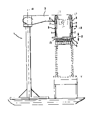
FIG. 1 is a sm~ scale and partly diagrammatic side
~iew of ~he apparatus according to the invention;
~ G~ 2 is an e~d view of the apparatus;
FIG. 3 is a top vie~ of the apparatus; and
FIG. 4 is a vie~ of a detail of an alternative arrange-
ment in accordance with ~he invention.
~r~1r~C ~ES~K1~
AS seen in the drawing, a transfer appa~atus 1 serves
to move ~LoU~ o~ obje~ts, here bottles 5, from a pickup station
9 ~ormed at a do~-.~LL~am end of an i:nput conveyor 10 to an v~L~L
or deposition st~tion 11 fo~med by a pallet or case conveyor lZ.
The apparatus 1 comprises a support arm 2 pivotal at its inner
end about an upright axis A by means o~ a motor illustrates
sche~atically at 15 and carrying at its outer end a pickup device
3 having a vertically displaceable pic~up ~ead or plate 4 pro-
CA 02259920 1999-01-22

20-JAN-99 12~ 4e FROM DUBNO-ROSS ID 718 601 1099 PAGE 10~1q
20992
vided With suctio~ grippers or strips 16 that can engage and li~t
the array of bottles 5.
This plate 4 is basically rectangular and horizontal.
I~ has two long sides ex~e~i n~ gen~rally tangentially of a
transport direction D, ~hich itself extends angularly of the axis
A. TWo ~ide belts 6 each have a lower end att~h~ to a respec-
tive one of these long sides and ar~ spanned at their upper ends
over respective rollers 13 that are synchronously oppositely
driven by a transmission dri~e ~ni~ shown s~h~ ,?tically at 14.
~hus the plate 4 is effectively hung on two planar st~etches of
the~e belts 6 which, while being capable of being rolled up, are
fairly stiff pa~allel to their vertical planes so that the plate
4 ~ill effectively be blocked against moving relative to the arm
2 in the direction D.
In addition a pair of scissor linkages 8 a~e provided,
each formed by upper and lower stiff arms 7. The lower end of
the lower arm 7 is pivoted on the plate about a ho~izontal axis
perpendicular to the direction D, its upper end is pi~oted on the
lower end of the respective upper arm 7, and the upper end of
this upper arm is pi~oted on the arm Z. Thus these linkages 8
effecti~ely prevent the plate 4 from moving perpendicular ~o the
direction D rel~tive to the arm 2 while still permitting it to be
moved up and down a~ the belts 6 are payed in and out.
FIG 4 shows how, instead of a pair of belts 6, only
one belt 6' ~ound over a single roller 13' is ~sed. The lo~er
CA 02259920 1999-01-22

20-JAN-99 12~48 FROM-DU~NO-ROSS ID-71~ 601 1099 PAGE ll~lq
209~2
end of this belt 6' is ~e~ lly attached to the plate 4. Here
the linkages 8 also serve to keep the plate 4 horizontal.
With this syste~ as sho~n in FIG. 1, ho~ever, acces~ to
the inside of the device is clearly possible. The co~bination of
the belts 6 and the scissor linkages 8 ensure~ however that the
lift plate 4, even when its lowermost posi~ion, will remain
perfectl~ aligned under the outer e~d of the arm 2 and will not
move parallel or transversely to the transport direc~tion D.
CA 02259920 1999-01-22

Representative Drawing
A single figure which represents the drawing illustrating the invention.
Administrative Status

2024-08-01:As part of the Next Generation Patents (NGP) transition, the Canadian Patents Database (CPD) now contains a more detailed Event History, which replicates the Event Log of our new back-office solution.

Please note that "Inactive:" events refers to events no longer in use in our new back-office solution.

For a clearer understanding of the status of the application/patent presented on this page, the site Disclaimer , as well as the definitions for Patent , Event History , Maintenance Fee  and Payment History  should be consulted.

Event History

Description Date
Inactive: IPC from MCD 2006-03-12
Application Not Reinstated by Deadline 2003-01-22
Time Limit for Reversal Expired 2003-01-22
Deemed Abandoned - Failure to Respond to Maintenance Fee Notice 2002-01-22
Inactive: Cover page published 1999-08-03
Application Published (Open to Public Inspection) 1999-07-24
Letter Sent 1999-06-22
Inactive: Single transfer 1999-06-01
Inactive: Correspondence - Formalities 1999-04-23
Inactive: Filing certificate - No RFE (English) 1999-04-09
Request for Priority Received 1999-03-23
Classification Modified 1999-03-16
Inactive: IPC assigned 1999-03-16
Inactive: First IPC assigned 1999-03-16
Inactive: IPC assigned 1999-03-16
Inactive: Filing certificate - No RFE (English) 1999-03-03
Inactive: Filing certificate - No RFE (English) 1999-02-26
Filing Requirements Determined Compliant 1999-02-26
Application Received - Regular National 1999-02-26

Abandonment History

Abandonment Date Reason Reinstatement Date
2002-01-22

Maintenance Fee

The last payment was received on 2000-12-12

Note : If the full payment has not been received on or before the date indicated, a further fee may be required which may be one of the following

  • the reinstatement fee;
  • the late payment fee; or
  • additional fee to reverse deemed expiry.

Please refer to the CIPO Patent Fees web page to see all current fee amounts.

Fee History

Fee Type Anniversary Year Due Date Paid Date
Application fee - small 1999-01-22
Registration of a document 1999-06-01
MF (application, 2nd anniv.) - small 02 2001-01-22 2000-12-12
Owners on Record

Note: Records showing the ownership history in alphabetical order.

Current Owners on Record
MSK-VERPACKUNGS-SYSTEME GESELLSCHAFT MIT BESCHRANKTER HAFTUNG
Past Owners on Record
FRANK MICHELS
NORBERT VERMEULEN
REINER HANNEN
Past Owners that do not appear in the "Owners on Record" listing will appear in other documentation within the application.
Documents

To view selected files, please enter reCAPTCHA code :


To view images, click a link in the Document Description column. To download the documents, select one or more checkboxes in the first column and then click the "Download Selected in PDF format (Zip Archive)" or the "Download Selected as Single PDF" button.

List of published and non-published patent-specific documents on the CPD .

If you have any difficulty accessing content, you can call the Client Service Centre at 1-866-997-1936 or send them an e-mail at CIPO Client Service Centre.


Document
Description 
Date
(yyyy-mm-dd) 
Number of pages   Size of Image (KB) 
Representative drawing 1999-08-03 1 7
Description 1999-01-22 7 257
Abstract 1999-01-22 1 24
Cover Page 1999-08-03 1 36
Abstract 1999-04-23 1 23
Claims 1999-04-23 2 53
Description 1999-04-23 7 235
Drawings 1999-04-23 4 63
Drawings 1999-01-22 3 76
Claims 1999-01-22 2 60
Filing Certificate (English) 1999-04-09 1 165
Filing Certificate (English) 1999-03-03 1 165
Courtesy - Certificate of registration (related document(s)) 1999-06-22 1 116
Reminder of maintenance fee due 2000-09-25 1 110
Courtesy - Abandonment Letter (Maintenance Fee) 2002-02-19 1 182
Correspondence 1999-03-03 1 36
Correspondence 1999-03-23 2 41
Correspondence 1999-04-23 15 401