Note: Descriptions are shown in the official language in which they were submitted.
CA 02260010 1999-01-08
WO98/01192 PCT~S97/12002
ROT-T-~ SKATE WITH BRAKE
This application is a con.tinuation-in-part of
application Serial No. 08/657,967, filed June 5, 1996,
which is a continuation-in-part of application Serial No.
08/472,382 filed June 7, 1995, the disclosures of which
are hereby incorporated by reference.
This invention relates tc, roller skates,
particularly of the in-line type, where a plurality of
wheels are aligned in a linear array. More particularly
the present invention is directed to in-line roller
skates having superior performance capabilities over
prior art in-line roller skates as to turning and
stopping.
FIELD OF THE lNv~wllON
Roller skates, particularly of the in-line type
which have a single linear array of wheels, are presently
very popular and in wide use. In fact, one area of
increasing popularity for in-line roller skates is in the
use of such skates to play "roller" hockey. These skates
tend to replicate the type of skating experienced with
ice skates. One problem with in-line roller skates, as
with all roller skates, is providing an effective
provision for stopping. One widely used stopping device
for roller skates is a rubber bumper extending downwardly
at the front or rear of the skate. To stop forward
skating motion, the skater tilts the toe or heel down to
cause the bumper to contact the ska~ting surface to
provide friction and resistance to the forward motion of
the skater.
However, in ice skating, a popular way of
stopping forward motion is known a~ the hockey stop. In
a manner similar to the use of skis, the skater makes a
sharp turn to the side and the blacLe of the ice skate is
turned transversely to the forward direction of the
skater. The skate blade, now posit.ioned transverse to
. . . .. . , . ~ .. .
CA 02260010 1999-01-08
WO98/01192 PCT~S97/12002
the previous direction of movement, slides along and digs
into the ice to provide a quick stopping action.
Another difference between in-line roller
skates and ice skates is that present in-line skates
provide multiple wheels all positioned at the same level
so that the full array of wheels are in contact with the
skating surface. Also, typically, some in-line roller
skates are provided with wheels which are substantially
short cylindrically shaped wheels or barrel shaped to
provide a relatively wider surface area of contact with
the skating surface. Other in-line roller skate wheels,
while having a wheel profile which provides a point
contact, does so in a manner which limits the angle with
the skating surface which the skate can safely be
employed. These factors tend to limit the ability of a
- skater using such prior in-line skates to make as sharp a
turn as çan be executed with ice skates.
Because conventional in-line roller skates have
somewhat limited turning capabilities, stopping is
usually accomplished by depressing the toe or heel to
place the rubber bumper in contact with the ground to
arrest forward momentum. If a skater is traveling at a
high rate of speed and needs to stop quickly, often such
quick stops cause the skater to fall forward. Most in-
line skaters wear protective gear such as helmets, knee
and elbow pads and hand pads to cushion these body parts
in the event of a fall. Despite the wearing of these
types of protective equipment many serious injuries
occur.
The present invention provides a safer and
quicker way of stopping which will eliminate many of the
injuries sustained by a forward head long fall. The
present invention also provides the ability to execute
sharper turns than can be executed with prior art in-line
roller skates.
Some in-line roller skates use a braking device
which attempts to duplicate the hockey stop. One such
CA 02260010 1999-01-08
WO98/01192 PCT~S97/12002
braking device is disclosed in U.S. Patent 4,618,158. In
this patent an in-line skate is disclosed for use by
figure skaters. A pair of in-line wheels at the toe and
heel area are rotatably secured by carrier yoke supports
to a mid-section support depending from a foot plate.
The yoke supports are able to rotate in a direction
transverse to, and about an axis parallel to, the skaters
foot in a toe to heel direction. A braking mechanism is
provided which includes a non-roun~ braking surface in an
axial extension in a housing rotatably secured to each
yoke support. A spring urges a ball bearing against the
non-round surface to provide a retarding force to the
rotation of the yoke supports as a function of the degree
of rotation. Wheel carrier yokes extend from opposite
ends of the brake yoke supports. Auxiliary rollers on
opposite sides of the main rollers, defining an extension
of the surface of the main spherical rollers, are
attached to the pair of main spherical rollers.
When the main rollers rotate about a
longitudinal front to rear axis in a hockey stop motion,
the auxiliary rollers, which are barrel shaped, contact
the ground and support the skate. The rotation in this
transverse direction activates the braking action to
resist the prior forward motion of the skater. This
skate is relatively complex, limits the number of wheels
that can be used and is relatively costly to fabricate.
A brake and wheel for in-line roller skates is
also disclosed in U.S. Patent No. 5,312,165. This
construction uses slip discs on a retainer ring forming
the skate wheels. The discs provide a transverse braking
skid to provide a friction engagement with the main
support structure while the skate moves in the transverse
direction.
U.S. Patent No. 5,246,236 discloses a roller
skate wheel for providing rolling action in forward and
lateral directions. The main rollers are provided with
secondary rollers which rotate about axes transverse to
CA 022600l0 l999-0l-08
WO98/01192 PCT~S97/12002
the longitudinal axis of rotation of the main rollers.
Metal friction applying brakes contact the secondary
rollers. The friction applied to the secondary rollers
controls resistance to lateral rolling to provide a
braking action.
Other skate and wheel constructions are
disclosed in U.S. Patents Nos. 5,199,727; 5,135,244;
4,838,564; 4,294,456; 3,936,061 and 2,166,767.
SUMMARY AND OBJECTS OF THE lNv~LlON
An in-line roller skate construction according
to the present invention has substantially spherically
shaped wheels attached to a foot receiving boot. The
spherically shaped wheels provide more of a point contact
between the wheels and the skating surface to more
closely replicate the blade edge contact between an ice
skate and the ice. All of the wheels are mounted for
normal forward and rearward rotation.
Ice skates are not provided with a flat lower
blade surface. Instead, the ice skate blades have a
slight curved shape in the heel and toe area so that the
heel and toe area curve upwardly. This blade feature
provides an ability to make sharper turns than if the
bottom of the blades were completely flat. In addition,
in ice skating, especially on turns, only one edge of the
2~ blade is in contact with the ice. The present invention
replicates these features of an ice skate blade to
provide an in-line roller skate with superior turning
capabilities over prior in-line skates where all the
rollers are mounted so that they are all in contact with
the skating surface.
To more closely replicate an ice skating
action, at least a pair of center in-line wheels are
mounted to extend further from the foot bed than the
wheels on the heel and toe area. The interior wheels are
3~ also mounted for limited pivoting movement. In normal
forward and rearward skating mode, as the skater moves,
the tendency is to lean forward so that the foot also
CA 02260010 1999-01-08
WO98/01192 PCT~S97/12002
pivots forward. The result is that; the boot pivots so
that the front three wheels are in contact with the
ground. On executing a turn, especially a sharp turn,
the skater leans backward so that t:he boot also pivots
back. The result is that as the boot pivots rearwardly
the three rear wheels now contact t:he ground. The
spherically shaped wheels also permit a skater to safely
skate at a steeper angle with the ground surface thus
allowing for sharper turn capabilit:y. This is the reason
that the skate of the present invention provides an
increased ability to execute turns
The present invention has also recognized that
increased stopping capability can be achieved on all
types of skating surfaces by using only the interior
wheels of the array for stopping purposes. Thus the
support system has been designed to permit a rocking
action to place only the interior wheels in contact with
the ground when stopping.
It has been found after experimentation with a
type of in-line roller skate as disclosed in parent
application Serial No. 08/657,967, that acceptable
stopping capability in a hockey stop maneuver can be
achieved without using an internal braking mechanism.
The material for the wheels, a high impact engineering
thermoplastic material resistant to wear and abrasion,
exhibits sufficient frictional drag on numerous types of
skating surfaces, e.g. concrete, asphalt and specially
prepared surfaces for competition skating, during a
hockey stop maneuver. Thus it has been found that with
the interior wheels (i.e., two or nnore interior wheels)
in contact with the skating surface a hockey stop
maneuver can be successfully employed.
Accordingly, it is an object of the present
invention to provide an in-line ro]ler skate with
superior quick stopping capability
CA 022600l0 l999-0l-08
WO 98/01192 PCT/US97/12002
It is a further object of the present invention
to provide an in-line roller skate with which a skater
can stop by executing what is known as a hockey stop.
A still further object of the present invention
is to provide an in-line roller skate which more closely
replicates the superior turning ability of ice skates.
Yet, another object of the present invention is
to provide an in-line roller skate which is safer to use
and which would be less prone to result in serious
injuries due to falls. These and other
objects and advantages of the present invention will be
more readily ascertainable with reference to the
following specification and drawings.
BRIEF DESCRIPTION OF THE DRAWINGS
Fig. 1 is an elevational view showing a
preferred embodiment of the in-line skate of the present
invention with the toe wheel and two interior wheels in
contact with the skating surface;
Fig. 2 is a view similar to Fig. 1 showing the
heel wheel and two interior wheels in contact with the
skating surface;
Fig. 3 is a view similar to Figs. 1 and 2
showing only the two interior wheels in contact with the
skating surface;
Fig. 4 is a partial elevational view taken
along the line 4-4 in Fig. 1;
Fig. 5 is a fragmentary sectional view taken
along the line 5-5 of Fig. 1;
Fig. 6 is an exploded elevational view of the
wheel mounting assembly;
Fig. 7 is an elevational view of the wheel
mounting assembly;
Fig. 8 is a partial cross sectional view of a
roller skate wheel of the present invention;
Fig. 9 is a fragmentary elevational view of a
prior art in-line roller skate wheel in an upright
position;
CA 022600l0 l999-0l-08
WO98tO1192 PCT~S97tl2002
Fig. 10 is a fragmentary elevational view of
the prior art in-line roller skate wheel at an angle to
the skating surface; and
Fig. 11 is a fragmentary elevational view of
the roller skate wheel of the present invention at an
angle to the skating surface.
DESCRIPTION OF THE PREFERRED EMBODIMENT
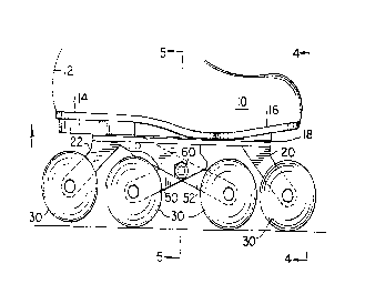
As seen initially in Figs. 1-3, the skate 10 of
the present invention includes a conventional shoe boot
12, having a heel area 14 and a toe area 16 to which is
secured a sole plate 18 in any convenient manner, for
example by rivets or any other suit:able bonding. A toe
wheel bracket mount 20 and a heel wheel bracket mount 22
are secured to the sole plate 18 in any convenient
manner. As also seen in Figs. 6 and 7 the toe wheel
bracket 20 includes a base plate 2~ and a forwardly
extending arm 26 provided with a through bore 28 to
accommodate the toe wheel assembly 30. Heel bracket
mount 22 includes a base plate 32 f-rom which extends a
pair of side members 34 and a rearwardly extending arm 36
having a through bore 38 therethrough to accommodate the
mounting of the heel wheel assembly 30.
A pivoting bracket 40 is mounted between the
extending side members 34 of heel bracket mount 22 to
accommodate the interior wheel assemblies 30. Pivoting
bracket 40 may include a first bore 42 which aligns with
bore 44 in side members 34 or a bore 46 which aligns with
through bore 48 in side members 34 Pivoting bracket 40
also includes extending arms 50 and 52 which include
through bores 54 and 56, respectively, to receive the
interior wheel assemblies 30.
As best shown in Figs. 6 and 7 pivoting bracket
40 is pivotally mounted in any convenient manner, for
example by a pivot axle 58 which extends through bores 42
and 44 or by a pivot axle 60 through bores 48 and 46.
Pivot axles 58 or 60 may be in the form of rivets, nut
and bolt assemblies or other suitable means for pivotably
CA 02260010 1999-01-08
WO98/01192 PCT~S97/12002
connecting pivoting bracket 40. Accordingly, pivoting
bracket 40 may be pivotably mounted in any convenient
manner. According to preferred embodiments, pivoting
bracket 40 is mounted by a nut and bolt assembly which
extends through bores 42 and 44 or through a nut and bolt
assembly which extends through bores 48 and 46.
As shown in Fig. 7 with this arrangement, the
pivoting bracket 40 can pivot about the pivot axle 58 in
the directions indicated by the arrow 62 in Fig. 7 or
about pivot axle 60 as shown in Fig. 3.
While a preferred embodiment uses a pivoting
bracket such is not necessary as the interior wheels may
be fixed. In such an embodiment the interior wheels are
fixed at a lower elevation than the toe or heel wheels.
According to another preferred embodiment, two
or more of the elements may be constructed as a single
element. Advantageously, the sole plate 18, base plate
24, base plate 32, side members 34, extending arms 36 and
26 are in the form of a single piece. Even better, the
single piece may also include shafts 68 extending through
bores 28 and 38. According to yet another embodiment,
pivoting bracket 40 may be a single piece that
incorporates extending arms 50 and 52 and bores 42, 46,
54 and 56. Even better, the single piece pivoting
bracket 40 may also include shafts 68 through bores 54
and 56.
The substantially spherical wheel assemblies 30
are all of the same construction and are provided for the
toe wheel, heel wheel and interior wheels. Each wheel
assembly 30, see Fig. 8 as well, is identical in
construction and includes a pair of semispherical wheel
halves 64 and 66 formed of a molded engineering
thermoplastic material secured for rotation about a shaft
68 in each of the bracket through bores 28, 38, 54 and
56. Each wheel assembly includes an internal bearing
housing 70 provided with a bearing ring 72. Shaft 68
includes a bearing shoulder 74 and roller bearings 76 are
CA 02260010 1999-01-08
WO98101192 PCT~S97tl2002
provided to abut against bearing ring 72 and bearing
shoulder 74. Shaft 68 is threaded at each end as at 78
to threadably receive a threaded retainer cap 80 to
retain each wheel half 64 and 66 on the shaft 68. A
cover cap 82 is provided to frictionally fit over
retainer cap 80 so that the exterior surfaces of each
wheel half have a semi-spherically exterior surface.
With the pivoting arrangement provided by
pivoting bracket 40 the interior wheel assemblies 30 can
pivot with respect to the boot 12. As best seen in
Figure 3, toe wheel bracket 20 and heel wheel bracket 22
are of a length so that the toe and heel wheel assemblies
are elevated slightly off the ground or skating surface.
In actuality during skating use the skater's boot pivots
in the direction of the broad arrows in Figs. l and 2 to
either place the toe wheel in ground contact along with
the interior wheels, see Fig. l, or the heel wheel in
ground contact along with the interior wheels, see Fig.
2.
In typical skating in a forward direction the
skater tends to lean forward so that the toe wheel and
the two intermediate wheels as depicted in Fig. l are
normally in contact with the ground. When it is desired
to execute a turn, as the skater turns the boot in the
direction of the turn, the skater's body leans back
slightly so that the heel and heel wheel pivot
downwardly, elevating the toe wheel in the position of
Fig. 2. In addition on executing a turn the skater's
body leans in the direction of the turn so that the foot
pivots about the vertical axis, as ;seen in Fig. ll, so
that the contact between the wheel assembly and the
ground or skating surface is only o;n one-half of the two
part wheel assembly. Because of the spherical shape of
the wheel assembly point of contact is maintained with
the skating surface as the spherical-like surface
provides multiple uniform tangent points between the
wheel surface and the ground at varying angles. Thus no
CA 022600l0 l999-0l-08
WO98/01192 PCT~S97/12002
matter how steep or severe an angle the skater's body and
feet form with the ground, the wheeled contact angle
remains uniformly constant. This enables the skater to
make a more severe or sharper turn than could be made
with prior in-line skates.
Reference is now made to Figs. 9 and lO which
show typical prior in-line skate arrangements. In these
arrangements a wheel 90 which has a rounded grounded
engaging surface 92 is mounted on a shaft 94 ]ournalled
within a support structure 96 having legs 98 and lO0 on
each side of the wheel 90. Typically the wheel is
mounted by bearings 102 on shaft 94 and the wheel
assembly is secured by end nuts 104 within the support
structure 96. Because of the more sharply radiused sides
of the wheel indicated by the arrow 106 in Fig. lO, there
is a limit to the angle from the vertical with which such
a skate can be safely employed. Additionally, this style
of wheel almost universally used in prior in-line skates,
has a radius of curvature for the same overall wheel
diameter than a wheel of the present invention. Thus, as
shown in Fig. lO, the maximum angle from the vertical at
which the skate can be safely employed is one where the
radiused portion 106 of the wheel remains in contact with
the ground. Any steeper angle bringing the flatter side
walls 108 of the wheel 90 into contact with the ground
will result in an immediate skid out and a fall. In
contrast, a steeper angle may be obtained with the semi-
spherical wheel construction of the present invention, as
shown in Fig. ll, so that a much steeper angle can be
utilized resulting in the ability to make sharper and
more precise turns.
When a skater desires to stop by executing the
hockey stop maneuver, the skater executes a sharp
transverse turn. At the same time the skater's body will
lean in the direction of the turn so that the skates will
pivot about the vertical axis to the position as may be
depicted in Fig. ll. It has been found that the friction
CA 02260010 1999-01-08
WO98101192 PCT~S97/12002
11
between the high impact engineering thermoplastic
material with which the wheels are made and typical
ground skating surfaces, such as concrete, asphalt and
specially prepared competition surfaces, is sufficient to
arrest the forward momentum of the skater. When
executing the stopping maneuver using the hockey stop,
the two interior wheels, as shown in Fig. 3, are the ones
that engage the ground surface with the toe and heel
wheels being elevated. It is thus apparent that most of
the frictional wear on the wheel surfaces will occur to
the two interior wheels and when the wheels are
sufficiently worn the toe and heel wheels may be
exchanged for the two interior wheels until wheel
replacement is necessary. It is thus seen that the
present invention provides a roller skate which has the
ability to more closely replicate an ice skate both as to
an increased ability to navigate sharper turns and also
to allow for rapid and safer stopping maneuver.
The disclosed embodiments are provided by way
of illustration and not limitation as further
modifications may be made without cleparting from the
spirit and scope of the present in~Tention as defined in
the following claims.