Note: Descriptions are shown in the official language in which they were submitted.
~_wm..,,.,.,~,m... ,. .w.~k,.~..»~~~~-,.....,.~.
CA 02260070 2005-02-02
FRAMELESS DOOR OR WINDOW CASEMENT ARRANGEMENT WITH
INSULATED GLAZING, AND PROCESS
FOR THE MANUFACTURE THEREOF
The present invention relates to a frameless door or
window casement arrangement with insulated glazing.
Usual door and window casement arrangements consist,
essentially, of a door or respectively, a window frame in which
there is inserted a plate arrangement. The window frame also
support the fittings by means of which the arrangement is
insertable in a usual mating frame (door jamb or respectively,
a window jamb or frame) and is adapted to be pivotable therein
and closeable relative thereto. In particular, there are also
known socalled turning/tilting fittings, by means of which the
window or door casing arrangement can be pivoted or tilted
relative to the mating frame in accordance with the position
of an actuating handle, whereby in a third position of the
actuating handle, by means of the fitting there can be achieved
a fixed latching in the mating frame, as a result of which
there is achieved a sealed condition with respect to the
exterior through the utilization of encompassing seals.
Usually, there are furthermore also employed socalled insulated
glazings for this purpose. With regard to the term insulated
glazing there is to be understood a plate arrangement
consisting of at least two glass plates which are retained at
a spacing relative to each other, in which there is gas tightly
glued in any encompassing socalled spacer, whereby through a
rim filling, in general a Thiokol'1'"' mass, there is achieved a
further sealing with regard to the exterior. The spacer
contains mostly a moisture-absorbent material, in order to
absorb moisture from the tightly closed off plate interspace
which is present between the two plates and the spacer. This
plate interspace can be evacuated, however, it can also be
-1-
n~....."."""~,.~... .._...,~"~...._ ,.W ~ , ,
CA 02260070 2005-02-02
filled with specified gas mixtures. The glass surfaces can be
equipped with heat protective, sound protective and/or
radiation protective coatings.
For door arrangements, for example, such as those which
are known for sports installations (socalled squash courts),
there are already employed single plate glazings without
frames. The fittings which are required for the rotational
movement of the glazing are clamped thereto or screwed thereon
by means of bore holes. In the event that rails are to be
attached along the edge, it is also possible to provide for
lift fitting arrangements, which, in any event, will again
impart a frame-like character.
Due to reasons of configurations it is a wish to also be
able to create frameless door and window casement arrangements
which contain an insulated glazing.
For this purpose, proposals have already been made. The
German Publication DE-AS-1212274 discloses an arrangement in
which the inwardly located glass plate possesses a peripherally
extending edge projection relative to the exteriorly located
glass plate, whereby there is contemplated a purely rotary
fitting which is either glued thereon or clamped thereto, and
essentially on the projection. This arrangement does not
permit the utilization of a turning/tilting fitting.
The German Publication DE-U1-93043$1 discloses an
arrangement with a spacer which is glued together with both
glass plates and carries a peripheral groove in its outwardly
facing section, which serves for the receipt of a fitting,
especially a turning/tilting fitting. The German DE-A1-4343521
discloses a basically similar arrangement in which the spacer
is extended rearwardly in such a manner that there is formed
an encompassing U-shaped recess, which closes off in a
generally close fit with the exteriorly located plate and which
serves for the receipt of the turning/tilting fitting. Also
in this case is the spacer adhesively glued between the two
glass plates.
-2-
.,". ~_ .",. , ...~"~,~.".".-m.-.
CA 02260070 2005-02-02
It has been found that such configured kinds of casement
arrangements do not satisfy the above-mentioned wish. An
important factor resides in that the interspace between the
plates of the insulated glazing must remain gas-tightly sealed
with respect to the exterior even over lengthier periods of
use. Even when one proceeds from the aspect that merely the
utilization of a glueing of the spacer without an edge filling
may lead to a sealed closure of the plate interspace over
lengthier periods of time, which according to current knowledge
~ could be achieved only with extreme difficulties, the forces
which are exerted during the specified actuation of the
fittings are such that already within a short period of time,
there is no longer provided the sealing condition.
Furthermore, the loads under certain conditions are also so
high that the glass edge will splinter, which is similarly
undesired. A further disadvantage is that the adhesive is
exposed to environmental influences, especially to sun rays,
as a result of which there is encountered an intense ageing
which again, in turn, leads to embrittlement and thereby to a
loss in sealing ability. Finally, it must be noted that the
coloration which may be necessary due to technological reasons
for the adhesive connection and for the spacer can lead to
significant adverse aesthetic influences. Moreover the edge
of the adhesive connection which is in general visible through
the glass plate is not configured quite linearly, which is also
undesired due to aesthetic reasons.
Accordingly, it is an object of the invention to provide
a frameless door or window casement arrangement with insulated
glazing which will fulfill the practical demands.
According to one aspect of the invention, there is
provided a frameless door or window casement arrangement with
insulated glazing which comprises an externally located glass
plate and an inwardly located glass plate with an encompassing
edge projection opposite the externally located glass plate.
A spacer is gas-tightly inserted generally along the edge
between the inwardly located and externally located glass
-3-
~....,.., ..... ,".,..»,~....~.,.~..,..~.. _.. ,
CA 02260070 2005-02-02
plates, and a similarly generally U-shaped outwardly opening
arrangement, which along an edge encompasses the spacer, is
positioned between the glass plates for receiving a fitting.
Actuating elements pass through the inwardly located glass
S plate through openings, and facilitate access to the fitting.
The generally U-shaped arrangement is formed by a profile
separated from the spacer and is embedded into an elastic edge
filling known per se for insulated glazings.
According to another aspect of the invention there is
provided a frameless door or window casement arrangement with
insulated glazing comprising an externally located glass plate
and an inwardly located glass ph.ate with a peripheral edge
projection opposite the externally located glass plate. A
spacer is gas-tightly inserted generally along the edge between
said inwardly located and externally located glass plates. A
similarly generally U-shaped outwardly opening arrangement
encompassing the spacer is positioned between the glass plates
for receiving a fitting. Actuating elements of the inwardly
located glass plate pass through openings and facilitate access
to the fitting. The casement arrangement is characterized by
the generally U-shaped arrangement being formed by a profile
separate from the spacer, which profile is positioned at such
a distance from the spacer between the glass plates, and is
glued therein, so that an air space is located between the
profile and an elastic edge filling known per se for insulated
glazings.
According to a further aspect of the invention, there is
provided a method for manufacturing the frameless door or
window casement arrangement with insulated glazing of the
present invention comprising the steps of:
(a) cutting a float glass plate for the externally
located glass plate;
(b) cutting a float glass plate for the inwardly located
glass plate;
-4-
CA 02260070 2005-02-18
(c) boring openings for the actuating elements of a
fitting in an edge region of the float glass plate for the
inwardly located glass plate;
(d) enamelling the edge region of at least the float
glass pl ate for the inwardly located glass plate;
(e) heat treating at least the float glass plate for the
inwardly located glass plate for burning in the enamelling;
( f ) effecting a concurrent or separate heat treatment
of
at least the float glass plate for the inwardly located glass
plate to form a single-plate safety glass plate;
(g) when required, coating at least one of the glass
plates
with a
heat protective,
sound
protective,
and/or
radiation
protective
layer;
(h) associating, inserting, assembling and glueing of
the
two glass
plates
and the
spacer
for an
insulated
glazing
in a
manner
known
per se;
(i) filling in of an edge filling mass for the insulated
glazing in a manner known per se;
(j) pressing the U-shaped profile into the edge filling
mass so that the edge filling mass contacts an outwardly
projecting
flange
at a remote
end of
an outer
arm of
the
profile with an end surface of the outwardly located glass
plate;
(k) curing the edge filling mass until reaching the
elastic
end condition
thereof;
and
(1) inserting and mounting the fitting and the actuation
elements thereof.
The basic concept of the first embodiment of the invention
lies in the recognition, that a profile embedded in the usual
edge fitting, which is independent of the spacer, is capable
of receiving the forces encountered at a specified use of the
fitting without disrupting the sealing ability. Thereby, it
is also essential that use can be made of the industrial
-5-
w~.. ""~.,. ~,.""."~.~,...~.,.....~.. .. ,
CA 02260070 2005-02-02
experience over the interim of many years in the manufacture
of insulated glazings, without any restrictions.
The basic concept of the second embodiment of the
invention is an arrangement, in which a similar profile, which
is independent of the spacer is inserted between the glass
plates, this profile, however, being located at a distance from
the spacer between the glass plates, especially glued in, that
there remains an airspace between itself and the elastic edge
filling with insulated glazing. This will counteract the
danger, that because of the air closure of the edge filling,
usually ThiokolT'", the latter becomes brittle and the sealing
capability of the insulated glazing is no longer afforded
towards the exterior. If, however, according to the invention
there remains this hollow space or airspace, than the edge
filling is aerated, as a result of which there is avoided the
mentioned danger. Here it is also important that there can be
used the industrial experience which has been employed in the
interim for many years in the manufacture of insulated
glazings, with the single restriction that, outside of the edge
filling, there must remain sufficient space between the glass
plates so that there can be inserted the profile.
Pursuant to a further aspect of the present invention, the
profile incorporates channels in its longitudinal arms and/or
its transverse arm, into which metal rods may be inserted or
embedded whereby, as required, in at least a few of the channel
sections there can be received screws. These metal rods are
expansion-restrictive elements, as a result of which there can
be avoided different expansions of the glass plate and profile
section during temperature changes.
Pursuant to a further aspect of the present invention,
metal strips are applied on the outwardly facing surfaces of
the arms of the profile element, in a manner such that the
glass plate contacts at least against the metal strips.
Moreover, this also serves the purpose of compensating for
fluctuations in the expansion during temperature loading
between the glass and material of the profile, which usually
-6-
~.~~ _..",. .. . P..,~~...~,.-,,..,~..
CA 02260070 2005-02-02
consists of plastic material, whereby these metal strips are
also carriers for the adhesive, which achieves the connection
between the glass plates and the profile element.
When, pursuant to a modification, the profile element of
the present invention is merely fixedly connected with the
encompassing side edge projection of the inwardly located glass
plate, especially glued thereto and merely supports itself
against the surrounding edge of the exteriorly located glass
plate, even when sealed, then special conditions in the
manufacture of the insulated glazing need not be considered.
This can relate to mass-produced items, in which there is then
additionally applied the inventively formed profile element.
It has been ascertained that an extremely good fixed connection
is attainable between the profile element and the inwardly
located glass plate which withstands the mechanical loads which
are caused by the receipt and the actuation of a fitting in the
profile element.
The utilization of laminated plate glass and especially
of single-plate safety glass for at least the inwardly located
glass plate, allows for further additional improvements. In
particular there can be created a light-impervious covering
which extends around the edges, which is extremely precisely
manufacturable and which facilitates the covering of the
unavoidable manufacturing imprecisions encountered during
manufacture of the insulated glazing. Furthermore, it is
possible to provide for an aesthetically attractive colored
configuration, without having to change the external surface
of the glass plate. Finally, it is possible more simply for
especially a single-plate safety glass to provide bore holes
which are adapted for the receipt of the actuating elements of
the fitting. In particular, with single-plate safety glass
there can be employed decorative capabilities which are merely
known in the artistic sector, namely especially an enamelling
along the edge region which affords, on the one hand a good
adhesive background for the glue adhesive material and the edge
w. .."..... ",..r~a",~"H"M,"~""~..,...... ,
CA 02260070 2005-02-02
filling mass, and on the other hand, which will not adversely
influence the sealing capability and strength.
Finally, through a suitable association of lip seals there
can be achieved a secure sealing toward the exterior of the
S casement arrangement which is inserted into the mating frame
even under extensive weathering.
The inventive process for the manufacture of a door or
window casement arrangement with insulated glazing pursuant to
the first embodiment utilizes most extensively known process
steps, whereby merely another sequence of steps is required,
and for an artistic working of float glass, known enamelling
can be industrially implemented.
The invention is now explained more closely on the basis
of the accompanying drawings illustrating examples of
embodiments, in which;
Figure 1 illustrates schematically in sectional the edge
region of an inventive frameless door or respectively, window
casement arrangement with insulated glazing pursuant to the
first embodiment;
Figure 2 illustrates schematically a plan view of such a
casement arrangement:
Figures 3 through 6 illustrate schematically the
arrangement and association of an inventive casement
arrangement in a condition while inserted into a mating frame;
Figure 7 illustrates schematically an embodiment of a
glass plate in the shape of a laminated glass plate;
Figure 8 illustrates schematically in section the edge
region of an inventive frameless door or, respectively, window
casement arrangement with insulated glazing pursuant to the
second embodiment;
Figure 9 illustrates schematically a plan view of such a
casement arrangement;
Figure 10 illustrates schematically in section the edge
region of a further inventive frameless door or respectively,
window casement arrangement with insulated glazing;
_g_
_..~...~"~.... __..~.~.~,..",~,."~...e.., ,
CA 02260070 2005-02-02
Figure 11 illustrates schematically in section the edge
region of a still further inventive frameless door or,
respectively, window casement arrangement with insulated
glazing;
Figure 12 illustrates schematically in section the edge
region of a further inventive frameless door or, respectively,
window casing arrangement with insulated glazing.
Figure 1 illustrates an inventive door or window casing
arrangement 1, which is constructed in accordance with the
principle of an insulated glazing. Accordingly, it is provided
with an outwardly or externally located glass plate 2, an
inwardly located glass plate 3 and a spacer 4. The spacer 4
is of commercially usual constructional type and consists of
a hollow profile element of rectangular cross-section, in the
inner space 5 of which there can be received a moisture-
absorbent material, whereby the inner space 5 stands in
connection with the plate interspace 7 through small bore holes
5.
As is usual with insulated glazings, the spacer 4 by means
of silicon or butyl adhesive strips 8 is inserted between the
glass plates 2 and 3 at a small distance from the outer edges
of the latter. Thereby, formed is an encompassing surrounding
edge joint, such as is usual for insulated glazings, which is
provided with an edge filling 9, which usually consists of
ThiokolT"'. Thus, the interspace 7 between the glass plates 2
and 3 is sealed with respect to the exterior in a gas and
moisture-sealed type manner. The plate interspace 7, as is
known per se, can be filled with a gas or (partially)
evacuated.
Pursuant to the first embodiment of the invention in the
edge filling 9 there is embedded a profile element 10 which is
separated from the spacer 4, which comprises an essentially U-
shaped cross-section and which is open towards the outside and
which serves for the receipt of a fitting, especially a
turning/tilting fitting of a usual type of construction.
Furthermore, the inwardly located glass plate 3 possesses a
-9-
_. _. . ..~_..~~"~, .~,
CA 02260070 2005-02-02
surrounding edge projection 11 opposite to the externally
located glass plate 2.
The profile element 10 comprises in cross-section an
outwardly located arm 12 and an inwardly located arm 13, which
extend essentially in parallel with the glass plates 2 and 3
respectively; however, which possess a small spacing so that
there can be implemented the embedding into the edge filling
9. A connecting or transverse arm 14, which due to
manufacturing reasons can possess a hollow space 15, can
incorporate ridges 16 on the outside which faces towards the
spacer 4, and which affords an improved embedding. Both arms
12 and 13 support themselves by means of small beads 17 and 18;
respectively, essentially linearly on the associated glass
plate 2 and 3, respectively, whereby this support is effected
essentially at the end of the arms 12 and 13, respectively,
which are distant from the plate interspace 7, as is
illustrated.
This will not only avoid the escape of the mass of the
edge filling during the embedding, but will also ensure that
there is a good guidance of the profile element 10 between the
plates 2 and 3, and thereby of the fitting which is received
in the profile element 10, such that any unnecessary mechanical
stresses are avoided.
The space between the arms 12, 13 and 14 comprises a
broader outer section 19 which allows for receiving and guiding
flat sections of the fitting, and a deeper section 20 which is
adapted to receive projections of the fittings having larger
dimensions which are required for actuating elements of the
fitting, the movement thereof not being disturbed or adversely
influenced. The two sections 19, 20 of the space are separated
from each other by a shoulder 21.
The hollow space 15 in the transverse arm 14, which is
provided due to manufacturing reasons, however, also
facilitates that the section which comprises the ridges 16 can
elastically deflect in the event that this becomes necessary.
-10-
,_....... ..~."",."F~s»~,-~~.
CA 02260070 2005-02-02
In the illustrated embodiment, the profile element 10
further comprises at the end of the externally located arm 12
which is distant from the plate interspace 7 an outwardly
projecting flange 22, which in the embedded position as
illustrated comes into contact against the end surface of the
externally located glass plate 2. The flange 22 can thus serve
as a stop and thereby assure a throughout uniform orientation
of the profile element 10 relative to the glass plates 2 and
3.
In the embodiment illustrated in Figure l, the inwardly
located glass plate 3 possesses an enamelling 23 which extends
around the edge facing towards the plate interspace 7, the
width of which is so dimensioned, as represented, that the
spacer 4 and the profile element 10, as well as the edge
filling 9 therebetween are covered.
It was found that such type of covering, such as the
enamelling 23, in its edge region can be produced extremely
precisely, which is not afforded for the positioning of the
silicon or butyl strips 8, so that there can be achieved an
aesthetically clean closure. Furthermore, this enamelling 23
renders the glass in this region opaque and/or colored in a
particular manner. This enamelling 23 is a special glass
technological treatment which requires a heat etching
procedure. Heretofore this was only known with artistic work.
However, it turned out that notwithstanding the enamelling 23
there is achieved a very good adhesive base for the silicon or,
respectively, butyl strips 8, and also for the edge filling 9,
so that gas tight and liquid tight closure is achieved for the
plate interspace 7.
Good results with the enamelling 23 could heretofore only
be achieved for single-plate safety glass. The employment of
single-plate safety glass has additionally the advantage that
through-openings which are required for the actuating elements
of the fitting can be applied in a simple and secure manner.
Figure 2 illustrates the arrangement of such through
bores, whereby this relates to a middle somewhat larger bore
-11-
m .... ,,. ".,."~._,- ... ,. . ,
CA 02260070 2005-02-02
24 for the through passage of the actuating element, and to
neighbouring somewhat smaller bores 25 for the fastening
elements of the actuating element. Further bores are not
required in accordance with the present state of the technology
for turning/tilting fittings. Single-plate safety glass has
also the further advantage that the edges can be easily
polished (chamfered) whereby the danger of injury is
extensively avoided. Moreover, there is also quite reduced the
danger of any glass splinters.
The advantages of such a frameless door or window casement
arrangement with insulated glazing are apparent. Besides all
advantages of an insulated glazing there is achieved an
extremely high light through-flow. Furthermore, it is easy to
take care of the arrangement. In contrast with a usual framed
window, there is no presence of any corners or edges, which
facilitates cleaning. Furthermore, it is possible to have a
free color selection, especially for an enamelling 23. The
servicing is unchanged with regard to usual framed windows,
inasmuch as identical turning/tilting fittings can be employed.
Architecturally viewed, for large building surfaces, the
position of fixedly installed glass plates and of casement
arrangements which can be opened, can be suitably selected,
since the frames are eliminated and also for shutter frames
there are no additional requirements to be considered.
Inasmuch as the profile element 10 serves merely for the
receipt and guidance of the fitting, it can be constructed in
a simple manner as a plastic material profile, for example, in
an extrusion process or an injection molding process.
Inasmuch as the plate interspace 7 by means of the spacer
4 is sealingly closed with respect to the exterior, the profile
element 10 can be constructed in multiple parts around the
circumference of the casing arrangement, whereby at joint
locations there need not be considered any high precision. For
example, there can be contemplated a construction which, in the
circumferential direction of the casement arrangement, has a
C-shaped or inverted C-shaped configuration, such as is
-12-
.~ .~.. . ....~ ..,~.",,~+~.....,...~ ~.,...~ ,
CA 02260070 2005-02-02
elucidated, for example, with regard to Figure 2. Two profile
parts l0A and lOB are arranged so as to contact each other by
means of contact joints 26. The position of the contact joints
26 and the width thereof is so determined, that any mass of the
edge filling 9 which escapes during embedding will not have any
influence during the movement of the fitting in the space 19
or, respectively, occasionally also in the space 20. Also in
this instance can the hollow space 15 in the transverse arm 14
be of significance. This facilitates also the embedding since
during the embedding, the displaced air can escape in a simple
manner. Of course it is also possible to have a multi-part
construction of the profile element 10, and the contact joints
26 can also be provided at the corners (not shown in detail).
On the basis of Figures 3 through 6 there are described
herebelow different embodiments with association to a mating
frame 30, whereby the same reference numerals as in Figure 1
designate the same components, and whereby deviations therefrom
are elucidated.
Furthermore, it is to be noted that, for example, in the
profile element 10, the hollow space 15 and the ridges 16 are
not particularly illustrated. Of course, those can be present
in the shape as in Figure 1 or in a similar form. Furthermore,
there is not illustrated in detail, that the beads 17 and 18
(Figure 1) can comprise taperings which are of assistance in
the manufacturing technology. In this connection, it is to be
mentioned that the profile element 10 need not be necessarily
a plastic material profile, but can also be constituted of
another suitable material; for example, aluminum, when this is
suitable for a particular use.
Furthermore, it is also again to be mentioned that in none
of the figures is there illustrated the commercially usual
fitting.
Quite in general is the casement arrangement 1 inserted
into a mating frame 30, whereby there is only represented the
closed position, in which the fitting which is received in the
profile element 10, through engaging means (not shown) is
-13-
.,.~.~M.".,",. .,.."...~w."..."~.....~ . ..
CA 02260070 2005-02-02
engaged in suitable grooves 31 in the mating frame 30, as is
known per se.
The mating frame 30 is fixedly anchored in the building
in a known manner which is not illustrated in detail. In
Figures 3 and 4, the mating frame 30 is formed by a socalled
thermally separated aluminum profile, i.e., through an inner
profile 32, heat-isolating connecting elements 33, 34, and an
external covering profile element 35. The covering profile
element 35 projects ahead relative to a window or door opening
to be closed in such a manner, that in the closed condition of
the casement arrangement 1 the edge region thereof comes into
a sealing contact against the covering profile element 35 by
means of a sealing element. In Figures 3 and 4, the element
of the covering profile 35 which projects the furthest into the
window opening and comes closest to the casement arrangement
1, carries a lip seal 36. The position of this lip seal 36 in
the exemplary embodiment is such that, viewed from the outside,
through the lip seal 36 and the covering profile element 35,
there is covered the region of the externally located glass
plate 32 of the casement arrangement l, which is associated
with the spacer 4, the edge filling 9 and the profile element
10. A covering, such as the enamelling 23 as represented for
the inwardly located glass plate 3 (Figures 1 and 2), is
thereby not necessary in this region. For another
configuration of the association of lip seal 36 and covering
profile 35 with regard to the casement arrangement 1, there
can, however, be also provided for the externally located plate
2, a covering which corresponds to the enamelling 23 (not
shown) .
Pursuant to Figure 3, at a portion of the covering profile
which is proximate to a building, there is retained a
further lip seal 37, whose lip comes into contact against a
portion of the profile 10. In this exemplary embodiment, the
flange 22 is not provided at the outermost end of the outwardly
35 located arm 12 which is distant from the plate interspace 7,
but evidences a certain spacing, through which there is defined
-19-
.,.... ".,_ . ~,.~,~",._...
CA 02260070 2005-02-02
a support surface 38 on the profile 10, against which lip seal
37 comes into contact when the casement arrangement 1 is in the
closed condition. Figure 3 also provides indications with
regard to the dimensioning of the projection 11 of the inwardly
located glass plate 3. This projection is to be dimensioned
so that at an open casement arrangement l, the elements of the
fitting which project away from the plate interspace 7 will not
be disruptive, especially will not be visible in the closed
condition of the casement arrangement l; however, the
engagement thereof into groove 31 upon actuation of the
actuating element (not shown) will be afforded.
In the embodiment pursuant to Figure 3, the covering
profile 35 is further configured so that between the outwardly
located lip seal 36 and the inwardly located lip seal 37 there
is defined a hollow space 39 in which, notwithstanding the lip
36, any penetrated water can run off and, when required, can
be guided through openings.
Figure 4 illustrates in contrast a somewhat modified
arrangement and construction of the second lip seal, which is
here identified by reference numeral 40 and which possess a lip
41 coming into contact against the outwardly located glass
plate 2, and a second lip 42 which comes into contact with an
end surface of the profile 10. Besides the hollow space 39,
there is accordingly defined between the lips 41 and 42 a
further hollow space 43, which can similarly serve for the
receipt of water which has penetrated notwithstanding all
previous sealing measures.
Figure 5 distinguishes from Figures 3 and 4, in that the
mating frame 30 is formed by a wood or plastic material profile
element 44, in which there is inserted a further configured lip
seal 45 which is comparably slightly different from lip seal
36 and a further slightly modified lip seal 46 comparable with
lip seal 40. Figure 6 illustrates similarly a wood or plastic
material profile 47 for the mating frame, whereby this profile
47 is; however, covered on the outside by further metal profile
48 such as an aluminum profile, which carries the lip seal 36,
-15-
_. ~ ..m.~...~. "~.."...,..~,.,.."~....".,.,.... _ ,
CA 02260070 2005-02-02
whereas the lip seal 46 as heretofore is inserted into the wood
or plastic material profile 47. It has been found that the
inventive casement arrangement 1 is insertable into mating
frames 30 of most differently configured shapes, whereas
through the casement arrangement 1 there can be achieved
basically required aesthetic effects, without neglecting the
sealing.
On the basis of Figure 1 there was shown that the
enamelling 23 produces an optical covering, whereby there is
concurrently afforded a good adherence for the silicon or,
respectively, butyl strips 8, as well as for the edge filling
9. This can also be achieved in a different manner, for
example, in a laminated glass plate arrangement 50 pursuant to
Figure 7. This consists of (at least) two glass plates 51 and
52 between which there is layered laminate-like a transparent
plastic foil 53. This plastic foil 53 is at the edge thereof
either rendered opaque through a treatment or replaced by an
opaque; or for example, colored foil 54, whereby the same
effect is achieved as would be by means of enamelling 23. Of
course, in this region there can also be carried out a
treatment of one of the glass plates 51 or 52 in order to
achieve the same effect. It is important, as mentioned, that
the optical covering of the region in which there are located
the spacer 4, the edge filing 9, and the profile 10, are under
the concurrent maintenance of the adherability with respect to
the edge filling 9 and the silicon or, respectively, butyl
strips 8. Of course, it is also possible to provide
combinations of laminated glass plate arrangements and single-
plate safety glass arrangements.
As already mentioned, the plate interspace 7 is fillable
with a gas or evacuable, as is usual. It is further usual to
undertake in the glass interspace 7 coatings of the glass
plates 2, 3 in order to achieve a heat protective, sound
protective and/or radiation protective effect (against UV or
IR radiation). Coating materials, layered constructions and
-16-
CA 02260070 2005-02-02
methods for producing such layers are basically known in many
modes.
During the manufacture of insulated glazings with the
utilization of coated glass plates, there is usually cut to
size a coated float-glass plate, freed along the edge thereof
from the coating and then conducted to the assembly. This in
any event, is not possible when there should be produced an
inventive casement arrangement 1, which contains an enamelling
23 or a comparable surface treatment of one of the glass plates
2 and/or 3, or in which there is employed a material which
requires a special treatment; for example, single plate-safety
glass.
Furthermore, during embedding of the profile 10 into the
edge filling 9 there must be taken care that this embedding is
effected as long as the material which is employed for the edge
filling 9 and the already filled in material is still
deformable, possesses at least a viscous consistency. In
accordance therewith, the known, usual process for producing
insulated glazings in specified steps must be modified and
changed.
Initially, the glass plates 2 and 3 are to be cut to size
in their dimensions, commencing from a usual float-glass plate.
Thereafter, the mentioned openings 24 and 25 are forward and
enamelling 23 is to be undertaken. In order that the
enamelling 23 penetrates into the glass material of the glass
plates 2 and 3, respectively, and achieves the necessary
adhesive base, the enamelling 23 is to be burnt in within the
scope of a heat treatment. Inasmuch as enamelling 23 in
accordance with the present state of the technology is only
durable for single-plate safety glass, the necessary heat
treatment which is employed for the production of the single-
plate safety glass is to be implemented concurrently or at a
different separate time.
In the event that the glass plates 2 and/or 3 are to be
coated, then the coating procedure is to be implemented,
whereby subsequent to the.coating procedure, the region in
-17-
rF ..n.,. .
CA 02260070 2005-02-02
which there are to be provided the spacer 4, the profile
element 10 and the edge filling 9, is to be freed from the
coating, or again freed therefrom.
Thereafter, in a usual manner, such as is known for
insulated glazings, there is implemented the assembly, meaning,
the spacer 4 is provided with the silicon or butyl strips 8 and
inserted between the plates 2 and 3 at the intended locations.
Thereafter, there is implemented the edge filling, which is
usually effected with ThiokolTM. Prior to the ThiokolT" edge
filling 9 reaching its cured elastic condition and being still
viscous, the profile 10 is embedded through pressing into the
edge filling 9. Only then are there undertaken the necessary
steps, such that the edge filling 9 is imparted the necessary
solid yet elastic consistency.
A commercial usual turning/tilting fitting can then be
inserted and mounted together with the associated actuating
elements, for which there are provided the bores 24 and 25.
Thereby, it is necessary that at least the bore 24 is extended
through the profile 10 insofar as during the preparation of
individual profile parts (for example, l0a and 10b) at suitable
locations. At this time, the casement arrangement 1 can then
be inserted into the window opening or respectively, into the
mating frame 30 thereof, in the usual manner and is ready for
operation.
In the following description of a second embodiment as
well as of further exemplary embodiment, to the extend possible
the same reference numerals are used as in Figures 1 through
7, whereby when showing the same element there is provided a
dash to the reference numeral concerned.
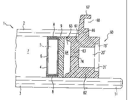
Pursuant to the second embodiment in accordance with
Figure 8 through 11, at a spacing from the edge filling 9
between the glass plates 2 and 3, there is inserted a profile
element 60 which is separate from the spacer 4, and which
comprises an essentially U-shaped cross-section and which is
open towards the exterior, and which serves for the receipt of
a fitting, especially a turning/tilting fitting of usual type
-18-
,.. i ,~,:., .~
CA 02260070 2005-02-02
of construction. Furthermore, the inwardly located glass plate
3 comprises a peripherally extending edge projection 11
relative to the outwardly located glass plate 2, whereby
inwardly located and outwardly located relate to the position
of the door or window casement arrangement 1 in a condition as
installed into a building. The profile 60 comprises in cross-
section an outwardly located arm 61 and an inwardly located arm
62, which extend essentially in parallel with the glass plates
2 and 3, respectively, and through which relative to the
profile 60, the outwardly located surfaces effect the fixed
connection to the glass plates 2 and 3, respectively,
preferably through an adhesive connection. A transverse arm
63 which connects the arms 61, 62 is spaced from the mass of
the edge filling 9 in such a manner that there is formed an
airspace 64 between edge filling 9 and profile 60. The
airspace 64 can be further increased by providing in the
transverse arm 63 relative to the portions of the arms 61 and
62 nearest to the spacer 4 a setback 65. In the transverse arm
63 there can additionally be provided through-openings 74 which
facilitate an air exchange with the airspace 64 towards the
outside, whereby these through openings 74 can also serve for
the receipt of fastening screws.
Assured hereby is a good guidance of the profile 60
between the glass plates 2 and 3, and namely also of the
fitting which is received in the profile 60, whereby there are
avoided unnecessary mechanical loads, especially those acting
on the spacer 4. Through the provision of the airspace 64 and
the possibility of an air exchange with the outside there is
avoided that the mass of the edge filling 9 will be embrittled
due to physical and/or chemical reactions, and thereby loses
its sealing effectiveness.
The space between the arms 61, 62 and 63 contains a wider
outer section 19', which enables the receiving of and guidance
of the sections of the fitting, and a deeper section 20' which
facilitates receiving projections of the fitting of larger
dimensions which are required for the actuating elements,
-19-
. , . " i. ..",.~
CA 02260070 2005-02-02
without that the movement is disturbed and adversely
influenced. The two sections 19' and 20' of the space are
separated from each other by means of a shoulder 21'.
In the illustrated exemplary embodiments, the profile 60,
at the end of the outwardly located arm 61 which is remote from
the plate interspace 7, comprises an outwardly projecting
flange or rim 66, which in the inserted condition, as
illustrated, comes into contact against the end surface of the
externally located glass plate 2. This rim 66 can therefore
serve as a stop and thus ensure a throughout uniform
orientation of the profile 60 relative to the glass plates 2
and 3.
In this embodiment, the inwardly located glass plate 3 can
also comprise an enamelling 23 extending around its edge (not
shown in Fig. 8, see Fig. 9), which faces towards the plate
interspace 7, whose width is so dimensioned, that as
illustrated in Figure 9, the spacer 4 and the profile 60 are
covered, as well as the edge filling 9 located therebetween and
the airspace 64.
It must be further mentioned that the profile 60 need not
necessarily be a plastic material profile, but can also consist
of another suitable material, for example, aluminum, as is
expedient for a particular instance of utilization.
The association of an inventive casement arrangement with
a mating frame is already extensively explained with regard to
preceding Figures 3 through 6. Accordingly, reference is made
to those explanations.
Therein, among other aspects, as already pointed out, the
sealing effect with regard to water toward the exterior is of
great significance. In addition to the improvement of the
sealing effect against water towards the exterior is achieved
in that the flange or rim 66 comprises an outwardly extending
projection 67, whereby the latter can show a generally U-shaped
recess 68 which is open in circumferential direction. Hereby,
there is facilitated the contact of further lip seals which are
-20-
. n, .,.. 1 ,.. ~M, ~. ,
CA 02260070 2005-02-02
fastened in the mating frame, additional obstruction to
weather-caused inflowing penetration of water.
Furthermore, it has been found that instead of the
covering which is formed by enamelling 23 there can also be
employed the covering as is extensively described in Figure 7.
Hereby, there is similarly made specific reference to these
explanations.
In the manufacture of the casement arrangement 1 pursuant
to this embodiment of the invention, case must be taken that
the edge filling 9 is already solidified to such an extent that
during the insertion of the profile 60 the edge filling 9 can
no longer flow. For the remainder, reference may be made to
the known usual process for the manufacturing of insulted
glazings.
During use there can be encountered significant
temperature fluctuations which, when.the differences in the
expansion between the glass of the plates 2 and 3, on the one
hand, and of the material of the profile 60, on the other hand,
are excessively large can lead to difficulties. This can
generate stresses which no longer allow for the secure handling
of the fitting, or through which is no longer afforded the
retention of the profile 60 between the glass plates 2 and 3.
The inventive solution of this problem is applicable to
the profile 60 pursuant to Figure 8, as well as to the profile
10 pursuant to Figure 1. However, this solution is merely
explained further on the basis of modifications of profile 60.
In accordance with the embodiment illustrated in Figure
10, the profile 60 comprises channels 69 or 70, respectively
in its arms 61, 62 and/or in its transverse arm 63, into which
there can be inserted or embedded metal rods 75 and 76,
respectively. These channels can, however, also be employed
for the receipt of screws for the fastening of the fittings,
possibly additionally to or alternatingly with such metal rods
75 and 76, respectively.
In the embodiment illustrated in Figure 11, metal strips
71 and 72, respectively are fixedly attached to the outwardly
-21-
,Ii.n",..
CA 02260070 2005-02-02
facing surfaces of the arms 61, 62 of the profile 60, in such
a manner that the glass plate 2, 3, come into contact with at
least the metal strips 71, 72.
The measure according to Figure 11 can additionally
achieve that the fixed connection between the profile 60 and
the glass plate 2, 3 is maintained through adhesives also under
intense temperature differences, such as may be encountered in
actual practice, in that there is selected a material for the
metal strips 71, 72 which is better suited as a support for the
adhesive than the material of the profile 60 itself. Of
particular advantage is aluminum or aluminum alloy.
The metal strips 71, 72 can be inserted through suitable
measures together with the manufacture of the profile 60,
especially by being molded therein. This can, for example, be
carried out by means of anchoring projections, such as for
example, projection 73 of the strip 72 in the arm 62 of the
profile 60.
However, other projections can be employed for this
purpose, such as projections provided over the longitudinal
extension of the metal strips 71, 72 or the like, which are
arranged distributed thereon.
Finally, there is to be mentioned that the measures
according to Figure 10 and the measures according to Figure 11
can be jointly provided.
Figure 12 similarly illustrates an inventive door or
window casement arrangement 1 which is constructed in
accordance with the principles of an isolated glazing. This
construction can be basically applied to a profile pursuant to
Figure 1 as well as a profile pursuant to Figure 8.
Pursuant to Figure 12, at a spacing from the edge filling
9 in the region between the glass plates 2 and 3; however
outside of the spatial covering, there is arranged a profile
80 which is separated from the spacer 4, which comprises an
essentially U-shaped cross-section and which is open towards
the outside and serves for the receipt of a fitting, especially
of a turning/tilting fitting of the usual type of construction.
-22-
..
CA 02260070 2005-02-02
Furthermore, the inwardly located glass plate 3 comprises an
encompassing edge projection 11 relative to the exteriorly
located glass plate 2, whereby the inwardly located and
outwardly located position of the door or window casement
arrangement 1 relates to a position as installed in a building.
The profile 80 comprises in cross-section an outwardly located
arm 81 and an inwardly located arm 82, which extend essentially
parallel to the glass plates 2 and 3, respectively, whereby the
outer surface of the inwardly located arm 82 relative to the
profile 80 provides for the fixed connection to only the glass
plate 3, preferably through an adhesive connection. A
transverse arm 83 which connects the longitudinal arms 81, 82
is spaced from the edge filling mass 9 in this exemplary
embodiment in such a manner as to form an airspace 84 between
the mass of the edge filling 9 and the profile 80. The
airspace 84 can be still further increased in that the
transverse arm 83 relative to the section of the longitudinal
arms 81 and 82 which are closest to the spacer 4 comprises a
setback 85. In the transverse arm 83, there can additionally
be provided suitable through-openings (not shown), through
which there is possible an air exchange with the airspace 84
towards the exterior, whereby these through openings can also
serve for the receipt of fastening screws.
The profile 80, in contrast with the previous embodiments,
however, is not fixedly connected with the externally located
glass plate 2, but merely lies sealingly against the latter,
especially along its encompassing end surface 27. In the
illustrated exemplary embodiment, the transitional region
between the outwardly located longitudinal arm 81 and the
transverse arm 83 of the profile is formed as a bead or
projecting edge 85, whose one surface is opposite to end
surface 27 of the externally located glass plate 2.
Advantageously the sealing contact is effected through a
sealing mass 88 between the bead 86 and the end surface 27 of
the externally located glass plate 2.
-23-
. ._ i """ .,
CA 02260070 2005-02-02
The bead 86 can be a component of an outwardly projecting
flange 87, as has previously been already explained, which in
the inserted condition does not only serve as a contact or stop
for a uniform orientation of the profile 80 relative to the
glass plates 2 and 3, but also serves as a means for guiding
off any water which has penetrated due. to weathering
influences.
The flange 87, can as illustrated further comprise an
elastic lip 89 which elastically contacts, in effect, proximate
the end surface 27, against the outside of the externally
located glass plate 2.
The space between the arms 81, 82, 83 of the profile 80
contains a wider outer section 19", which can receive and guide
the sections of the fitting, and a deeper section 20" for the
receipt of larger projections of the fittings which are
required for the actuating elements, without that the movement
thereof is disturbed or adversely influenced. Both sections
19" and 20" of the thus formed space are separated from each
other by a shoulder 21".
Through the selected embodiment there is assured, a good
guidance of the profile 80 in the region between the glass
plates 2 and 3, but also a good guidance of the fitting which
is received in the profile, without that this causes, on the
one hand, any unnecessary mechanical loads to the spacer 4 and,
on the other hand, to the connection between the glass plates
2 and 3. Through the provision of the airspace 84 there is
avoided that the mass of the edge filling mass 9 will become
embrittled due to physical and/or chemical reactions, and
thereby loses its sealing effect, as has been explained
hereinabove.
Merely schematically represented is an enamelling 23 which
is provided on the inwardly located glass plate 3 extending
around the edge facing towards the plate interspace 7, and
whose width is so dimensioned that the spacer 4 and the profile
80, as well as the edge filler 9 located therebetween, and the
airspace 84 are covered. The advantage of this type of
-24-
. .,....a .,...~ ...,
CA 02260070 2005-02-02
covering, such as the enamelling 23, is further extensively
illustrated hereinabove.
Inasmuch as the profile 80 serves merely for the receipt
and guidance of the fitting, it can be constructed in a simple
manner as a plastic material profile; for example, by an
continuous extrusion processor injection molding process.
The profile 80, around the circumference of the casement
arrangements, can be constructed by a plurality of parts, as
further explained hereinabove. It is to be mentioned, that also
in Figure 12, the commercially usual fitting is not
illustrated.
It can be further mentioned, that the profile 80 need not
necessarily be a plastic material profile, but can be
constituted of another suitable material, for example aluminum,
when this is expedient for a particular case of utilization,
especially for the fixed connection with the encompassing edge
protection 11 of the inwardly located glass plate 3.
An addition to the improvement of the sealing ability
against water entering from the exterior is achieved by the
flange 87 which is constructed as an outwardly projecting
protuberance, whereby this can show a generally U-shaped recess
which is again in the circumferential direction.
As a result, there is facilitated the contact of further
lips of lip seals of sealing arrangements which are fastened
in the mating frame, which also constitutes an additional
obstruction to the entry of water caused by weathering
conditions.
Furthermore, it should be noted, that instead of the
covering which is formed by the enamelling 23, there can also
be employed the covering which is described extensively with
regard to Figure 7.
In the manufacture of an inventive casement arrangement
1 in accordance with this embodiment, there can be made use of
insulated glazing which are mass produced, in which a glass
plate which is later employed as the inwardly located glass
plate comprises a projection 11 along its edge. Expediently,
-25-
, , "..,i. ""A ....
CA 02260070 2005-02-02
after the filling 9 has solidified, the profile 80 is
positioned in the region of the projection 11 along the
circumference thereof, whereby the transitional region which
is formed as a bead 86 comes into contact against the end
surface 27 of the externally located glass plate 2; as
required, with the interposition of the seal 88.
During use there can be encountered significant
temperature fluctuations which, on the one hand, when the
differences in the expansion between especially the glass of
the glass plate 3, and on the other hand, the material of the
profile 80 is too excessive, can lead to difficulties. There
can be generated stresses which no longer allow for the secure
handling of the fitting, or through which the retention of the
profile 80 on the glass plate 3 is no longer afforded.
To that extent there can be basically made use of the
measures which are explained with regard to Figures 10 and 11.
In the embodiment illustrated in Figure 12, a metal strip
90 is fixedly attached to the outwardly facing surface of the
inwardly located arm 82 of the profile 80, in such a manner
that the glass plate 3 by means of its projection 11, comes at
least into contact with this metal strip 90. This measure can
additionally achieve that the fixed connection between the
profile 80 and the glass plate 3 will be maintained through
adhesion even under intensive temperature differences, such as
are encountered in practice, in that for the metal strip 90
there can be selected a material which is better adapted as a
support for the adhesive material than that of the profile 80
itself. For instance, aluminum or an aluminium alloy, is
particularly advantageous.
The metal strip 90 can be inserted or, in particular, cast
in through suitable measures during the manufacture of the
profile 80. This can be effected in particular through
anchoring projections, such as for example, projection 91 on
the metal strip 90. Furthermore, there can also be additionally
provided a metal rod, as mentioned further hereinabove, in the
transverse arm 83.
-2 6-
r~ ..... z .,
CA 02260070 2005-02-02
It is, however, advantageous to provide as a projection
of the metal strip 90 this metal rod 92, which facilitates the
anchoring of the metal strip 90 and the body of the profile 80,
as well as the region of the transitional region which is
formed as the bead 86, as is illustrated. This metal rod 92 can
have through openings (not shown) which facilitate an air
exchange with the airspace 84 whereby moreover there can also
be received screws in the event that this is required.
In the described embodiment there is illustrated that the
outwardly located side of the outwardly located longitudinal
arm 81 is generally in an alignment with the inwardly located
surface of the externally located glass plate 2. This has
certain advantages in conjunction with the cooperation of the
lip seals which are arranged in the mating frame. However, it
is important that also the outwardly located longitudinal arm
81 is sufficiently stable, so that no problems are encountered
upon receipt of the fitting.
There is still to be mentioned that, already in
conjunction with the insulated glazings there can be applied
known measures for creating the impression of a lattice window
or a bulls-eye-glass in the same manner, whereby additionally
there can be made use of the measure of the enamelling pursuant
also for this purpose.
In total there is created a frameless door or
respectively, window casement arrangement, which can afford for
practical application the necessarily required sealing
capability of the plate interspace 7, whereby in addition,
there can be achieved a multiplicity of aesthetic and
architectural effects, and further the secure undisturbed
manipulation of the fittings.
-27-