Note: Descriptions are shown in the official language in which they were submitted.
CA 02260l98 l998-l2-29
W O 98/01641 PCTIGB97/01815
LATCH UNIT AND ASSEMBLY, AND METHOD OF
OPERATING A LATCH UNIT
F~ELD OF THE INVENTION
This invention relates to a latch unit and assembly, and to
a method of operating a latch unit. In particular it
relates to a latch unit having a slidable bolt, typically
for securing a movable panel to a fixed member, such as to a
10 part of a frame for the panel.
In this specification, "left" and "right", "forward",
"rearward" and similar geometric terms refer to parts in a
typical orientation of use as shown in Fig.1, unless
15 otherwise specified.
BACKGROUND TO THE INVENTION
20 When it is desired to secure a movable panel to a fixed
member such as to an upright of an outer frame memlber, it is
known to use a sliding bolt mounted to the panel, the bolt
end being fitt~able behind or within a keeper carried by the
frame, whereby to effect the securement. The keeper
25 typically is a plate mounted over a recessed portion of the
fixed ~ember or an apertured body secured to the fixed
me~ber. The lpanel typically is a hinged panel which closes
perpendicularly or nearly so to the fixed member and thus to
the keeper. In use the bolt is slidable between (a) a
30 holding or forwardly extended position in which the bolt end
can fit within the recess or aperture provided by the keeper
whereby to sec:ure the panel in the closed condition, and (b)
a rearwardly retracted or non-holding position in which the
bolt end cannot engage the keeper whereby to allow the panel
35 to move relative to the fixed member.
Usually the Ibolt is mounted in a bolt housing, and is
slidable between guides carried by the bolt housing.
SUBSTITUTE SHEET (RULE 26)
CA 02260198 1998-12-29
W O 98/01641 PCT/GB97/01815
Various types oiE bolt and bolt assembly are known, some of
which are lockable in the holding position.
5 One type of bolt assembly has resilient bias means for the
bolt, the resilient bias means conveniently being a
compression sprLng or a leaf spring mounted in the bolt
housing, the spring urging the bolt end towards the holding
position, the bolt end having a chamfer; in the condition of
10 use the chamfer faces the keeper as the panel is being
closed. As the panel is moved to its closed condition the
keeper forces back the bolt against the spring and into its
non-holding position, until the bolt end is aligned with the
recess or aperture whereupon the spring urges the bolt into
15 its holding position; this action is often referred to as
latching, and the spring as a latch spring, whilst the bolt
assem~lies of which the biassed and chamfer-ended bolts form
a part, are referred to herein as latch units.
20 One common form of latch unit is designed to be fitted to
the interior sur~Eace at the rim of an inwardly opening door,
such as a front door of a domestic dwelling. For
simplicity, the following disclosure will refer to a latch
unit for such u~;e (rim latch); however, the latch unit of
25 the invention can also be morticed into a door or other
panel, and can be fitted to windows and other movable
panels. The keeper for such latch unit will usually be
formed with an aperture, sized to receive the bolt end and
needing only to be affixed to the door frame or other fixed
30 member in order to provide in the holding position a self-
contained embracement of the bolt end, and for simplicity
also the following disclosure will assume such a keeper.
A latch unit typically has a bolt which can be moved
35 rearwardly (retracted) by an actuator. The actuator will
often be connected at one side to a "thumb-turn" (usually
the side which will be to the inside of the building in
use), the thumb-t.urn being rotated to move the bolt from its
SUBSTITUTE SHEEl (FlULE 26)
CA 02260198 1998-12-29
W O 98/01641 PCT/GB97101815
holding to its non-holding position. At its other side the
actuator will often be connected to the barrel of a lock
(usually the side which will be to the outside of the
building in use), so that fro~ that side it is necessary to
5 insert a key to retract the bolt from its holding position.
~ecause the bolt of a latch unit would otherwise
automatically ~enter the keeper ("latching" action) when the
door is closed, it is common to require a device to be
10 ~itted which an occupier can operate in order to permit the
force of the Latch spring to be over-ridden. Such device
will therefore permit the bolt to be retained in its non-
holding position i.e. non-latching condition, so that the
occupier for instance does not need to use a key or other
15 operating mean; in order to regain entry into the premises.
A means to over-ride the latch spring, and to maintain the
bolt away from its holding position is often referred to as
a "latch-back" device.
DESCRIPTION OF THE PRIOR ART
It is known to provide a latch-back device for a rim latch,
the device typically comprising a slida~le plate which can
25 be moved subst:antially perpendicularly to the direction of
movement of an extension secured to a short latch bolt.
Whilst the latch bolt is being held in its non-holding
position, as by a thumb-turn, the plate can be moved into
engagement with a recess or the like in the extension for
30 the latch bolt so that thereafter the plate retains the
extension and thus the latch bolt in its non-holding
position. When the occupier or other person desires to re-
activate the latch unit, the plate is moved to release the
extension whereby to permit the latch bolt to move axially,
35 specifically t:o be urged to its holding position by the
latch spring.
SUBSTITUTE SHEET (RULE 26)
.. . .
CA 02260198 1998-12-29
098~01641 PCT/GB97101815
It is possible to operate this known latch-back device with
one hand, but this is difficult and often awkward to
achieve, so that in practice setting the latch-back device
often re~uires the simultaneous use of both hands, one hand
to rotate and hold the thumb-turn and the other then to move
the plate. In addition, the operating means for the plate
is small, and can be difficult to grip so that the latch-
back device may be seldom or never used by the elderly or
disabled. It is believed that these known (two-handed)
latch-back devices are particularly difficult to operate for
those suffering from arthritis or rheumatism. The known
latch back devices are not safe to use on the safety exit
("panic") doors of multi-occupier premises.
STATEMENT OF THF INVENTION
We seek to provide a latch unit having a retaining means or
latch-back device which reduces or avoids the disadvantages
with the known devices, and which can be simpler to operate.
In particular, we seek to provide a latch unit in which the
latch-back device can automatically re-set, and which can
thereafter be released by one hand. We therefore seek to
provide a latch unit in which the latch-back device does not
require a latch-back plate or the like to be moved by the
user whilst the bolt is simultaneously being held manually
in a retracted position against the force of the latch
spring.
According to one feature of the invention we provide a
method of operating a latch unit, the latch unit having a
bolt, the bolt being movable in a first direction between a
holding position in which a part of the bolt projects from
the housing and a non-holding position in which the said
part projects l~sss from the housing, the bolt being biassed
towards the holdinq position, the latch unit having
actuating means for moving the bolt in said first direction
from its holding position to its non-holding position
SUBSTITUTE SHEET (RULE 26~
CA 02260198 1998-12-29
W O 98/01641 PCTIGB97/01815
against said bias, the bolt having a retaining means to
retain it at a position away from its holding position,
characterised in that the retaining means can be activated
to retain the bolt only upon further movement of the bolt in
5 the said first direction to a position rearwards of the non-
holding position.
The retaining means is automatically activated upon said
further movement of the bolt in the said first direction.
10 The retaining means is conveniently a pivoted lever, or
alternatively a slidable plate or lever.
Preferably, in the non-holding position the said part does
not project from the housing, perhaps being flush with a
15 planar outer forward surface of the housing.
It is thus a i.'eature of this invention that the bolt may be
moved by the actuating means in the first direction from its
holding positi.on to its non-holding position and that only
20 upon further or continued movement in said first direction
effected by the actuating means can the retaining means be
effective. In particular, we provide a method of operating
a latch assembly which includes a latch unit secured to a
movable panel and a keeper secured to a fixed member, the
25 latch unit including a bolt having a bolt end, the bolt
being urged by a first resilient bias means in a forward
direction such that in a closed condition of the assembly
the bolt end is located by the keeper in a holding condition
wherein opening movement of the panel relative to the fixed
30 member is inhibited, the bolt end being shaped so that
during relative movement of the panel and fixed member
~ towards the said closed condition of the assembly the bolt
end can be moved by the keeper against the first resilient
bias means re,arwardly into a non-holding position in which
35 said opening movement of the panel relative to the fixed
member is not inhibited by the keeper, there being actuating
means alternatively to move the bolt end into said non-
holding posit.ion, and retaining means engageable with the
Sl)BSTlTUTE SHEET (RULE 26)
CA 02260198 1998-12-29
WO 9~/01641 PCT/GB97/01815
bolt to hold the bolt against forward movement characterised
by engaging the retaining means with the bolt only when said
bolt is rearward of said non-holding position.
5 It is a feature of the invention that the retaining means is
engaged with the bolt only when the bolt has been moved
positively rearwards of said non-holding position for
instance direct movement as by a finger-pull from the non-
holding position or indirect movement as by operation of a
10 "panic bar" (with the bolt not pausing at the non-holding
position). The retaining means is not used to secure the
bolt in the non-holding position but only in the retained
position rearwardly thereof.
15 The bolt is s].idably mounted in a housing the housing
carrying a second resilient bias means the second resilient
bias means urging the retaining means towards the bolt and
into a bolt retaining condition.
20 Thus with the bolt end in its first holding position being
held by a keeper the bolt may then be moved from that
holding position to its non-holding position (as by a thumb-
turn) but the (retracted) bolt position reached following
this movement of the bolt is not sufficient either to
25 activate the re!taining means or to permit the retaining
means to be activated i.e. a further movement of the bolt by
means of a further (partial) rotation of e.g. the thumb-
turn is requir~d. In an alternative embodiment suited to
operation by a panic button or bar, the bolt can be moved
30 directly to the retained position i.e. through and beyond
the non-holding position suited for normal panel (typically
an exit door for a multi-occupier building) opening and
closing.
35 The bolt may simply be a latching bolt but preferably is
securable in the holding position to provide a combination
latch bolt and locking bolt.
SUBSTITUTE SHEET (RULE 26)
.
CA 02260198 1998-12-29
W O 98/01641 PCT/GB97~01815
According to another feature of the invention, we provide a
latch unit which includes a bolt, a housing for the bolt,
guides for the bolt in the housing, first resilient bias
means for the bolt in the housing, the first resilient bias
5 means urging one end of the bolt in a forwards direction
towards a hol.ding position externally of the housing, and
retaining mea~s for the bolt, the retaining means having an
inactive posit:ion in which the bolt is free to move relative
to its guides and an active position in which the retaining
10 means provide-; a holding action whereby to retain the bolt
against movement in the said direction, characterised in
that the retaining means is resiliently biassed towards its
active conditi.on.
15 According to a further feature on the invention, we provide
a latch unit ~which includes a bolt, a housing for the bolt,
guides for the bolt in the housing, first resilient bias
means for the bolt in the housing, the first resilient bias
means urging one end of the bolt in a forwards direction
20 towards a holding position externally of the housing, and
retaining means to provide a holding action whereby to
retain the bolt against movement in the said direction,
characterised in that the retaining means comprises a peg
and slot arra,ngement, and in that a second resilient bias
25 means effects engagement between the peg and slot to permit
said holding action.
The peg and slot are arranged such that the retaining means
holds the sai.d one end of the bolt rearwards of the non-
30 holding position reached by the bolt end when pushed back bya keeper during latching i.e. in the latch back position.
Preferably, the slot is carried by a lever. The second
resilient bias means acts against one of the said peg and
35 lever. A dislengaging means can be urged against said one of
said peg and slotted lever to overcome said second resilient
bias means whereby to permit the bolt to be urged towards
the holding position by the first resilient bias means.
SUBSTITUTE SllEET (RULE 26)
CA 02260198 1998-12-29
WO 98/01641 PCT/GB97101815
Preferably, the disengaging means is an extension of the
lever, the disengaging means projecting externally of the
housing. Prefe:rably the slot is in a movable lever and the
5 peg is carriecl by the bolt. Desirably, the slot is
connected to a second slot, the peg being movable along said
second slot by said first resilient bias means when said
second resilient bias means has been overcome by the
disengaging means whereby the bolt end is moved into said
10 holding position by the first resilient ~ias means.
Usefully, the second slot has a ramp portion; usefully the
first resilient bias means also holds said peg and ramp
portion in engagement.
We also provide a latch assembly which includes a movable
panel and a fixed member, the panel having mounted thereto a
latch unit as herein defined and the fixed me~ber having
mounted thereto a keeper for said one end of the ~olt, the
20 one end being locatable by said keeper whereby to secure the
panel and the fixed member against relative movement, the
one end being retainable by the retaining means at a
position away from the keeper and away from the non-holding
position whereby to permit relative movement between the
25 panel and the fixed me~ber.
Accordingly, when the assembly is correctly fitted, the bolt
has three positions, a (forward) holding position in which
it can engage the keeper, a (rearward) non-holding position
30 in which it cannot engage the keeper, and a (more rearward)
retained "latch back" position in which it cannot engage the
keeper and in wh~ich it is retained by the retaining means.
When used to hold open an emergency exit door when operated
by a panic control, the bolt may be passed through the non-
35 holding position without dwelling i.e. without the ~olthaving a stationary intermediate position.
SUBSTITUTE SHEET (RUI E 26)
CA 02260198 1998-12-29
W O 98/01641 PCTIGB97101815
BRIEF DESCRIPTION OF THE DFU~WINGS
The invention will now be described, by way of example, with
reference to 1he accompanying drawings, in which:-
Fig.l is a side view of a latch unit according to the
invention, partly in section, the bolt being in
its holding position;
10 Fig.2 is a side view of the latch assembly including the
unit: of Fig.1, the bolt being in the retained
posi,tion;
Fig.3 is a side view of part of an alternative latch
unit:, the bolt being in the non-holding position;
Fig.4 is a side view of another alternative latch unit:
Fig.5 is a perspective view of a latch assembly
including a further alternative embodiment of
latch unit;
Fig.6 is a sectional view of part of the latch unit of
Fig.,5;
Fig.7 is another sectional view of the latch unit of
Fig.,5; and
Fig.8 is a side view of part of yet another alternative
embodiment of latch unit.
D~SCRIPTION OF THE PREFERRED EMBODIMENTS
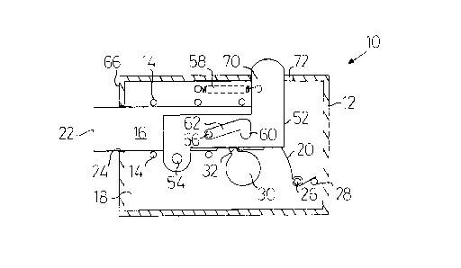
35 The latch un:it 10 of Fig.l comprises a rigid, preferably
metallic, housing 12, which carries guides 14 for an
axially-extending rigid (preferably metal) bolt 16. In this
embodiment the guides 14 comprise a number of spaced posts
SUBSTITIJTE SHEET (RUI~ 26)
CA 02260198 1998-12-29
WO 9B/01641 PCTIGB97/0181
-- 10 --
upstanding from housing base 18, but in alternative
embodiments the guides could be parallel upstanding rails,
or a combination of posts and rails.
s Bolt 16 has a holding position (Fig.l), and intermediate
non-holding position (similar to that of Fig.3), and a
retained position (Fig.2).
The bolt 16 is biassed leftwards by first or latch spring
10 20, as shown in Fig.1 into its holding position in which the
bolt end 22 extends from the housing 12, through housing
bolt opening 24, sufficient to engage in or behind a keeper.
The latch spring 20 is coiled around upstanding post 26 and
one end acts against post 28. In an alternative embodiment
15 the latch spring is a coil spring as in the embodiments of
Figs. 4 and 7.
The latch unit 10 includes an actuator 30 for the bolt, the
actuator having an arm 32 which is engageable with a (rear)
20 surface 34 of a recess in the bolt such that clockwise
rotation (as viewed) of the actuator causes rearward axial
retraction movement of the bolt 16 in a first direction
against latch spring 20; anti-clockwise rotation of actuator
30 subsequently allows the latch spring 20 to effect forward
25 movement of the bolt 16 to the holding position. In a
typical rim latch secured to the inner face of an external
door of a building, one side of the actuator will be
connected to the barrel of a lock, so that the actuator can
only be key-rotated from that side - usually the side which
30 will face outwardly of the building; the other side (inside
the building) of the actuator will typically be connected to
a thumb-turn or the like. Neither the lock barrel nor
thumb-turn are shown in the drawings, since suitable
embodiments are well known to and widely used by those
35 skilled in this art.
In use as a latch assembly 40 as shown in Fig.2, housing 12
is fixed to a d~or 42 whilst keeper 44 is fixed to a frame
SUBSTITUTE SttEET (RULE 26)
~ , , ~
CA 02260198 1998-12-29
W 098101641 PCT/GB97101815
-- 11 --
member 46 for the door. The bolt 16 is movable by arm 32
from its holding position as shown in Fig.l rightwards to
its non-holding position in which the bolt end 22 can pass
the keeper edge 48, so that the door 42 can be opened or
5 closed.
It will be understood that one face of the bolt end 22 is
chamfered, in known fashion. In the embodiment shown in
Figs. 1 and 2 the latch unit is designed to be held in the
10 closed condit:ion following latch unit movement in the
direction into the paper, so that it is the unseen face of
the bolt end 22 which is chamfered. It will also be
understood thalt when the latch unit 10 is moved towards its
"closed" condition against keeper 44, the bolt end 22 is
15 first forced back to its non-holding position against the
force of latch spring 20 before returning forwardly to its
holding position when bolt end 22 becomes aligned with the
keeper aperture. The keeper has a ramp 50 to cooperate with
the chamfer of the bolt end 22, to assist the rearwards
20 movement before the forwards latching action.
In accordance with one aspect of the invention the latch
unit lO also includes a lever 52 which pivots about fixed
housing post ')4. The bolt 16 carries a peg 56. The lever
25 52 is biassed (anti-clockwise) into the position shown in
Figs. l and 2 by second or retainer spring 58. The lever 52
has a first s:Lot 60 which is connected to a second slot 62,
both slots 60,62 being sized to accommodate the peg 56.
30 In the holding position of Fig.l, the peg 56 is adjacent the
forward edge of the second slot 62 (the peg 56 and the
forward edge of second slot 62 thus together determining the
holding position of the bolt); rearward (i.e. rightward as
drawn) axial retraction movement of the bolt 16 between
35 guides 14 (as by clockwise rotation of actuator 30 or
engagement of bolt end 22 with keeper 44) causes relative
movement betwe!en the peg 56 and second slot 62.
SUBSTITUTE SHEEl (RULE 26)
CA 02260198 1998-12-29
W ~ 98/01641 PCT/GB97/01815
- 12 -
During the init:ial relative movement between the peg 56 and
second slot 62 the peg 56 is moved along slot ramp surface
64 causing the lever 52 to pivot clockwise, extending and
tensioning the retainer (coil) spring 58 and holding peg 56
5 and ramp surface 64 in engagement; in an alternative
embodiment the spring 58 could be a leaf spring or
equivalent e.g. a torsion spring. This initial movement
continues unti] the bolt end 22 reaches the non-holding
position, and thus will encompass the normal movement range
10 of the bolt during its latching action.
In accordance with a feature of the invention, the actuator
30 can be rotated (clockwise as viewed) to effect further
axial movement of the bolt 16 in the rearward direction,
15 beyond the non-holding position. The peg 56 is thereby
moved into alignment with lever first slot 60, with retainer
spring 58 then acting to pivot lever 52 anti-clockwise
whereby to locate peg 56 in first slot 60; with the peg 56
so located the bolt 16 is held in its retained or latch-back
20 position.
Ramp surface 64 is longer than the distance moved by the
bolt end betwee!n the non-holding position and the holding
position, i.e. further rearward movement of bolt 22 is
25 required from t~le non-holding position to reach the retained
or bolt latch-balck position.
It will thus be understood that when the bolt 16 is moved to
its non-holding position (in which the bolt end 22 can pass
30 the keeper edge 48, i.e. the bolt end 22 is flush or
substantially flush with the housing face 66), the peq 56 is
(only) part-way up the ramp portion 64, and that such
rearward retract:ion movement of the bolt to its non-holding
position can be by way of either the actuator or by the bolt
35 16 engaging its keeper 44 during door closure. It will also
be understood that further movement of the bolt 16 is
necessary before the retaining means is activated, i.e.
before the peg 56 has completed its movement up ramp portion
SUBSmUTE SHEET (RULE 26)
CA 02260198 1998-12-29
W O 98/OlC41 PCT/GB97101815
- 13 -
64 and entered and lodged in first slot 60 whereby to
provide the Latch-back condition. Thus, in the retained
latch-back condition of the bolt shown in Fig.2, the bolt
end 22 is within the housing 12, in a position into which it
5 can only be driven rearwardly by the actuator 30, not by the
keeper 44.
As a further feature of the invention lever 52 has an
extension 70. In this embodiment (a) extension 70 is
10 generally parallel to first slot 60, (b) second coil spring
58 is connected to extension 70, and (c) housing 12 has an
opening 72 through which a terminal portion of extension 70
projects so as to form a "finger-press". Thus in use, the
latch-bac~ can be released or de-activated by (downwards)
15 finger pressure on extension 70, to pivot lever 52 until peg
56 is aligned with second slot 62 whereupon latch spring 20
can move bol1: 22 forwards either until surface 34 of the
bolt recess lFig.2) abuts arm 32, or (if actuator 30 has
already been rotated fully anti-clockwise, or is free to be
20 driven anti-clockwise by the bias of latch spring 20) until
the peg 56 engages the forward end of the second slot 62.
In an alterna,tive embodiment the extension 70 is connected
to a hoop by way of a cord or chain, the hoop being operable
25 to move the lever 52 in the direction to de-activate the
latch-back device, useful for someone unable to apply
sufficient single-finger pressure to extension 70 but who
c~n apply the weight of their arm. In addition, a rod may
be connected directly to the bolt 16, which rod extends
30 through the rear wall of the housing; the rod can be shaped
so as to be more easily grasped and pulled than the grasping
and rotating of a thumb turn, so facilitating the use of the
latch unit es~pecially by the elderly or infirm.
35 Although we prefer that the peg be carried by the bolt and
that the slots are within the lever, we do envisage that the
slots could be replaced by depressions and that the
SUBSTITUTE SHEEt (RULE 26)
, .. --.. . . .
CA 02260198 1998-12-29
W O 98/01641 PCT/GB97/01815
- 14 -
depressions could alternatively be in the bolt (with the peg
on the lever).
In one embodiment the peg 56 stands slightly proud of the
5 lever 52 and provides a column upon which a guide roof for
the bolt rests,, so that the bolt is in part being guided
between the housing base 18 and this guide roof, as well as
between upstanding posts 14; in an alternative embodiment a
removable cover (similar to cover 76 of Fig.5) for the bolt
lo housing provides the guide roof.
In the alternative embodiment of Fig.3, the second slot 162
has a ramped portion 164 and a forward portion 178 which is
substantially parallel to the longitudinal axis of bolt 116.
15 Whilst the bolt 116 moves between its holding position and
its non-holding position as shown, the peg 156 moves along
the forward port;ion 178. The resistance to such movement is
provided only by the latch spring 120. When it is desired
to move the bolt: to its retained position, further rearwards
20 movement by the actuator 130 causes the peg to move along
ramped portion 164 (pivoting lever 152) and into first slot
160 as described in relation to Figs. 1 and 2. Resistance
to such further movement is provided both by the latch
spring 120 and also by the retainer spring (not shown in
25 this figure). It can be arranged that there is a noticeable
or significant increase in resistance when it is desired to
move the bolt 116 into its retained position, so that it is
less likely that the bolt will be further moved to its
retained position when this is not desired. Alternatively
30 stated, with the embodiment of Fig.3 it will be apparent to
the user (from the sudden increase in the retraction force
which has to be applied to the bolt) when the bolt is being
moved from its; non-holding poisition and towards its
retained position (in which position the door is openable
35 freely by the orcupier and intruders alike), i.e. so that
the retained position is less likely to be adopted
inadvertently.
SUBSTITUTE SHEET (RULE 26)
CA 02260198 1998-12-29
W O 98/01641 PCTtGB97/01815
This embodiment also permits the retainer spring (not shown
in Fig.3) to be untensioned or under minimum tension during
the latching action, (i.e. as compared to the embodiment of
Figs. 1 and 2 it is only necessary to tension the retainer
5 spring of the Fig.3 embodiment whilst the bolt is being
"further" moved to its retained position); this will likely
result in an extended life for the retainer spring. In
addition, this embodiment minimises wear and frictional
resistance bet:ween the peg 156 and the ramp portion 164 and
lo also between the lever 152 and pivot post 154, over the
traverse of t;he bolt 116 during its latching action i.e.
between the holding and non-holding positions. Furthermore,
during latching move~ent the extension (not shown in Fig.3,
but similar to the extension 70 of Fig.l) is not moved e.g.
15 inwardly of the housing, but in contrast during further
movement of the latch bolt 116 in this first direction
towards the latch-back position the extension is moved
inwards relative to the housing noticeably (by the ramped
portion 164) before snapping out again when the peg 156
20 enters the first slot 160, so that a visual indication of
the activation of the retaining means is also provided.
The arrangement of Fig.4 is somewhat similar to that of
Fig.3, in that the second slot 262 has a ramped portion 264
2S and also a forward portion 278 which is qenerally parallel
to the longitudinal axis of bolt 216. However, the latch
unit 210 shown in Fiq.4 is adapted to cooperate with an open
ended keeper (not shown) which can enter aperture 280
between the housing 212 and a receptor 282. Bolt 216 has a
30 first holding position (as shown), and a second holding
position in which the bolt end 222 enters receptor 282. The
~ receptor 282 acts as a second keeper, and is carried by the
housing 112 - as generally described in our copending
international patent application PCT/GB96/01530, the
35 disclosure of which is incorporated herein by reference.
The advantageous embodiment of Figs.5-7 shows a latch unit
for use as a "panic" bolt e.g. for use on an emergency exit
SUBSTITUTE SHEET (RULE 26)
. . , _
CA 02260198 1998-12-29
W 098101641 PCTIGB97/01815
- 16 -
door, in which a button 384 can be pressed to move the bolt
316 rearwardly from its holding position directly to its
retained position (by way of and past its non-holding
position). In the orientation of Figs. 5 and 7, rearward
5 movement of the bolt is towards the right as drawn, whilst
in the orientation of Fig.6, rearward movement of the bolt
is towards the Left as drawn.
In this embodiment the button 384 is mounted on a rod 386
10 which is pivotably attached to a pivot plate 388. Pivot
plate 388 is mounted upon fixed pivot 390, and has an end
392 which engages abutment surface 394 of the bolt 316. A
particular advantage of this arrangement is that a user of
the panic bolt can (and in a panic usually will) move the
lS bolt 316 in one movement to the latch-back position,
ensuring that t]he door remains unlatched and so openable by
rescuers from outside. This contrasts with the disadvantage
of prior art panic bolts which automatically re-latch if
allowed to close (so that a person still inside the building
20 who has been overcome by fumes or who is otherwise unable
themselves to operate the panic bolt to re-open the door is
isolated from rescuers outside the building, and can thus be
trapped inside). For subsequent normal use, the bolt can be
re-set quickly and simply to the normal latching condition
25 by depression of the finger press 370 or equivalent.
It will be understood that the button 384 can be replaced by
a pivoting plate, sometimes referred to as a "paddle", or
equivalent operating member.
In the embodiment of Fig.8, the retaining means is slidable,
and comprises a plate 452 slidable between guides 454. The
bolt 416 has a recess 460 which can accommodate a peg 456
carried by the retaining plate 452. Retaining plate 452 is
35 biassed upwardly as drawn by coil spring 458. As the bolt
416 is moved bel:ween its holding and non-holding positions,
the peg 456 runs along the bottom edge 462 of the bolt, with
the spring 458 under compression; when the bolt is moved
SUBSTITUTE SI~EET (RULE 26)
CA 02260198 1998-12-29
W O 98101641 PCT/GB97tO1815
back to its retained position as shown, the retainer spring
458 urges the peg 456 into the recess 460. Thereafter,
depression of the plate extension 470 (as by finger
pressure) can release the peg 456 from the recess,
5 permitting the latch spring 420 to urge the bolt 416 towards
its holding position.
In this embodiment, the retaining plate 452 lies between the
bolt 416 and the base 418 of the housing 412, so that the
10 bolt 416 is spaced from the base 418 by the thickness of the
retaining plate 452 and the corresponding depth of the
guides 454; in an alternative embodiment the retaining plate
lies between the bolt 416 and the cover (not shown).
15 An advantage of the constructions described is that the bolt
16,116,216,316,416 can be of substantially constant
dimensions throughout its length, and its part within the
latch housing need not (as in some known latch unit
constructions) be of reduced dimensions (and thus of reduced
20 strength against attempted unlawful entry). The reduced
dimensions of these prior art latch-back retaining members
may be necessary so that they can be accommodated within
their respective housings.
SUBSTITUTE SHEET (RULE 26)