Language selection

Search

Patent 2260305 Summary

Third-party information liability

Some of the information on this Web page has been provided by external sources. The Government of Canada is not responsible for the accuracy, reliability or currency of the information supplied by external sources. Users wishing to rely upon this information should consult directly with the source of the information. Content provided by external sources is not subject to official languages, privacy and accessibility requirements.

Claims and Abstract availability

Any discrepancies in the text and image of the Claims and Abstract are due to differing posting times. Text of the Claims and Abstract are posted:

  • At the time the application is open to public inspection;
  • At the time of issue of the patent (grant).
(12) Patent: (11) CA 2260305
(54) English Title: ELECTRONIC APPARATUS
(54) French Title: APPAREILLAGE ELECTRONIQUE
Status: Expired and beyond the Period of Reversal
Bibliographic Data
(51) International Patent Classification (IPC):
  • H05K 07/20 (2006.01)
  • H01L 23/427 (2006.01)
(72) Inventors :
  • GATES, WILLIAM GEORGE (United Kingdom)
(73) Owners :
  • LUCENT TECHNOLOGIES INC.
(71) Applicants :
  • LUCENT TECHNOLOGIES INC. (United States of America)
(74) Agent: KIRBY EADES GALE BAKER
(74) Associate agent:
(45) Issued: 2002-09-03
(22) Filed Date: 1999-01-25
(41) Open to Public Inspection: 2000-07-25
Examination requested: 1999-01-25
Availability of licence: N/A
Dedicated to the Public: N/A
(25) Language of filing: English

Patent Cooperation Treaty (PCT): No

(30) Application Priority Data: None

Abstracts

English Abstract

Electronic apparatus is contained in a heat dissipative external enclosure. The enclosure contains at least one unit contained in a thermally conductive internal housing providing RF isolation and mounted on a wall of the enclosure in thermal contact therewith. A wall of the unit has a first recess receiving the evaporator of a heat pipe. The heat pipe is clamped between the external enclosure and the internal housing. The condenser of the heat pipe is lower than the evaporator and is received by a recess in the wall. The evaporator is clamped in the recess by a clamp member e.g. another unit. Because the heat pipe is clamped at its ends, it does not need to be an interference fit in either recess and may thus easily be removed. The inner housing can maintain RF isolation.


French Abstract

Un appareillage électronique est contenu dans une enceinte externe dissipant de la chaleur. L'enceinte contient au moins une unité contenue dans un logement interne conducteur de chaleur, assurant une isolation aux RF et fixé sur une paroi de l'enceinte en contact thermique avec celle-ci. Une paroi de l'unité comporte un premier renfoncement accueillant l'évaporateur d'un caloduc. Le caloduc est serré entre l'enceinte externe et le logement interne. Le condensateur du caloduc est plus bas que l'évaporateur et est logé dans un renfoncement dans la paroi. L'évaporateur est serré dans le renfoncement par un élément de serrage, par exemple une autre unité. Le caloduc étant serré par ses extrémités, il n'a pas besoin d'être ajusté de manière serrée dans un renfoncement et peut ainsi être facilement retiré. Le logement interne peut assurer une isolation aux RF.

Claims

Note: Claims are shown in the official language in which they were submitted.

-6-
CLAIMS
1. Electronic apparatus contained in a heat
dissipative external enclosure, the external enclosure
containing at least one unit contained in a thermally
conductive internal housing providing RF isolation and
mounted on a wall of the external enclosure in thermal
contact therewith; a wall of the unit having therein a
first recess receiving the evaporator of a heat pipe, the
heat pipe being clamped between the external enclosure
and the internal housing, the condenser of the heat pipe
being lower, in use, than the evaporator, being received
by a recess in the wall of the external enclosure and
clamped therein by a clamp member.
2. Electronic apparatus as claimed in claim 1,
wherein the first recess is located adjacent one or more
power components inside the internal housing.
3. Electronic apparatus as claimed in claim 1 or
2, wherein the condenser is clamped in its recess by
another unit which fulfils the function of clamp member.
4. Electronic apparatus as claimed in claim 1, 2
or 3, wherein the heat pipe has two opposed substantially
flat sides, and the first and second recesses are flat
bottomed.

Description

Note: Descriptions are shown in the official language in which they were submitted.


r CA 02260305 1999-O1-25
- 1 -
ELECTRONIC APPARATUS
This invention relates to electronic apparatus
contained in a heat dissipative external enclosure.
In the absence of forced convection, electronic
apparatus will be hotter at the top of its external
enclosure than at the bottom. The situation is worse for
apparatus which is sealed for use outside where internally
generated heat has to be dissipated by the external
enclosure. Ideally components which dissipate large amounts
of heat would be sited lower in the external enclosure than
components which dissipate less heat. That is not always
possible.
Heat pipes have been used to conduct heat away from
components to cooler positions in the external enclosure.
Conventionally, the evaporator of a heat pipe is in direct
thermal contact with a power component e.g. by clamping or
bonding. The condenser is conventionally pressed into a
groove in the wall of the external enclosure, being an
interference fit in the groove so as to ensure good thermal
contact. The heat pipe has a round cross section and the
groove has a corresponding round bottom. The step of
pressing the heat pipe into the groove may also be used to
distort the pipe so that it finishes flush with the top of
the groove.
Removal of the heat pipe is virtually impossible
which makes removal of the circuit board on which the

CA 02260305 1999-O1-25
- 2 -
component is mounted very difficult.
In same external enclosures individual units have to
be isolated from one another against radio frequency (RF)
interference by closed internal housings. It would be
difficult to maintain the RF isolation round a heat pipe
which would have to enter the internal housing.
Against this background there is provided electronic
apparatus contained in a heat dissipative external
enclosure, the external enclosure containing at least one
unit contained in a thermally conductive internal housing
providing RF isolation and mounted on a wall of the external
enclosure in thermal contact therewith; a wall of the unit
having therein a first recess receiving the evaporator of a
heat pipe, the heat pipe being clamped between the external
enclosure and the internal housing, the condenser of the
heat pipe being lower, in use, than the evaporator, being
received by a recess in the wall of the external enclosure
and clamped therein by a clamp member.
Because the heat pipe is clamped at its ends, it
does not need to be an interference fit in either recess and
may thus easily be removed. The inner housing can maintain
RF isolation.
The first recess is preferably located adjacent one
or more power components inside the internal housing.
In order to reduce the size of the external
enclosure, the condenser is preferably clamped in its recess
by another unit which fulfils the function of clamp member.

. . . ...~;, ".;~:~ . an
CA 02260305 2002-05-28
- 3 -
That other unit may comprise only low power components.
Most preferably the heat pipe has two opposed
substantially flat sides, and the first and second
recesses are flat bottomed. This simplifies machining the
recesses, and allows the surface of the wall or clamp
member opposite the first and second recess respectively
to be plain.
In accordance with one aspect of the present
invention there is provided electronic apparatus
contained in a heat dissipative external enclosure, the
external enclosure containing at least one unit contained
in a thermally conductive internal housing providing RF
isolation and mounted on a wall of the external enclosure
in thermal contact therewith: a wall of the unit having
therein a first recess receiving the evaporator of a heat
pipe, the heat pipe being clamped between the external
enclosure and the internal housing, the condenser of the
heat pipe being lower, in use, than the evaporator, being
received by a recess in the wall of the external
enclosure and clamped therein by a clamp member.
One embodiment of the invention will now be
described, by way of example, with reference to the
accompanying drawings, in which:
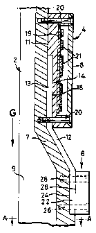
Figure 1 is a schematic section through part of
electronic apparatus embodying the invention and showing
internal housings mounted on a wall of an external
enclosure
Figure 2 is a view of the internal housings taken
from the right of Figure l:
Figure 3 is a section on arrows A-a of Figure 1; and
Figure 4 is a sectional view of a heat pipe on
arrows B-Bm in Figure 2.

i
CA 02260305 2002-05-28
- 3a -
Referring to the drawings, a base station of a
mobile communications network has electronic apparatus
mounted in an external enclosure 2, only part of which is
shown in the drawings. The enclosure contains, amongst
other units, a wide band power amplifier 4, contained by
an aluminium internal housing 8 to provide RF isolation,
and a duplexer 6. The internal units, including the power
amplifier 8 and the duplexer 6, are mounted in thermal
contact with a wall 7 of the enclosure 2. The enclosure 2

CA 02260305 1999-O1-25
- 4 -
is manufactured from light metal and has extended surfaces
or fins 9 so as to dissipate heat generated by its internal
units including the power amplifier 4 and the duplexer 6.
The enclosure 2 is environmentally sealed.
Convection within the enclosure is not possible due to very
small internal spaces left by the units contained therein.
Convection round the external enclosure is not forced so the
top of the enclosure is hotter significantly than the
bottom. A relatively large amount of heat is generated by
the power amplifier 4 compared with the duplexer 6 and it
would be better to locate the power amplifier below the
duplexer in a lower temperature. Other design constraints
require the power amplifier 4 to be above the duplexer,
however.
In order to reduce the temperature of the power
amplifier 4, a heat pipe 12 is provided. The evaporator 13
of the heat pipe 12 is received by a recess 14 in the wall
11 of aluminium housing 8. The heat pipe has two generally
flat opposed sides 16. The bottom 18 of the recess 14 is
plain. The surface of the part of the wall 7 on which the
power amplifier 4 is mounted is plain. The power amplifier
4 is mounted on the wall by four screws 20. The depth of
the recess 14 compared to the thickness of the heat pipe
between its flat sides is such that the heat pipe is clamped
between the wall 7 and the bottom 18 of the recess in the
housing 8. As may be seen in Figure 4, the width of the
recess is sufficient that the heat pipe 12 is a clearance fit

r~ CA 02260305 1999-O1-25
- 5 -
and can easily be removed.
Inside the housing 8, components are mounted on a
circuit board 19. The recess 14 locates the evaporator 13
adjacent power components 21, such as power transistors,
which dissipate large amounts of heat.
The condenser 22 of the heat pipe 12 is received by
a recess 24 in the wall 7. The bottom of the recess is
plain. The width of the recess is sufficient that the
condenser is a clearance fit so that it can easily be
removed. The condenser is clamped in the recess by a clamp
member in the form of the duplexes 6. The duplexes 6 is
mounted by screws 26. It has a plain surface 28 for thermal
contact with both the wall 7 and the heat pipe 12. The
depth of the recess 24 compared to the thickness of the heat
pipe between its flat sides is such that the heat pipe is
clamped between the bottom of the recess 24 in the wall 7
and the plain surface 28 of the duplexes 6.

Representative Drawing
A single figure which represents the drawing illustrating the invention.
Administrative Status

2024-08-01:As part of the Next Generation Patents (NGP) transition, the Canadian Patents Database (CPD) now contains a more detailed Event History, which replicates the Event Log of our new back-office solution.

Please note that "Inactive:" events refers to events no longer in use in our new back-office solution.

For a clearer understanding of the status of the application/patent presented on this page, the site Disclaimer , as well as the definitions for Patent , Event History , Maintenance Fee  and Payment History  should be consulted.

Event History

Description Date
Time Limit for Reversal Expired 2016-01-25
Letter Sent 2015-01-26
Inactive: IPC from MCD 2006-03-12
Grant by Issuance 2002-09-03
Inactive: Cover page published 2002-09-02
Amendment After Allowance Requirements Determined Compliant 2002-07-02
Letter Sent 2002-07-02
Inactive: Final fee received 2002-05-28
Pre-grant 2002-05-28
Inactive: Amendment after Allowance Fee Processed 2002-05-28
Amendment After Allowance (AAA) Received 2002-05-28
Notice of Allowance is Issued 2002-03-08
Letter Sent 2002-03-08
Inactive: Approved for allowance (AFA) 2002-02-27
Application Published (Open to Public Inspection) 2000-07-25
Inactive: Cover page published 2000-07-24
Letter Sent 1999-06-07
Inactive: Single transfer 1999-05-13
Inactive: First IPC assigned 1999-03-16
Classification Modified 1999-03-16
Inactive: IPC assigned 1999-03-16
Inactive: Courtesy letter - Evidence 1999-03-09
Inactive: Filing certificate - RFE (English) 1999-03-03
Application Received - Regular National 1999-03-01
Request for Examination Requirements Determined Compliant 1999-01-25
All Requirements for Examination Determined Compliant 1999-01-25

Abandonment History

There is no abandonment history.

Maintenance Fee

The last payment was received on 2001-12-28

Note : If the full payment has not been received on or before the date indicated, a further fee may be required which may be one of the following

  • the reinstatement fee;
  • the late payment fee; or
  • additional fee to reverse deemed expiry.

Patent fees are adjusted on the 1st of January every year. The amounts above are the current amounts if received by December 31 of the current year.
Please refer to the CIPO Patent Fees web page to see all current fee amounts.

Owners on Record

Note: Records showing the ownership history in alphabetical order.

Current Owners on Record
LUCENT TECHNOLOGIES INC.
Past Owners on Record
WILLIAM GEORGE GATES
Past Owners that do not appear in the "Owners on Record" listing will appear in other documentation within the application.
Documents

To view selected files, please enter reCAPTCHA code :


To view images, click a link in the Document Description column (Temporarily unavailable). To download the documents, select one or more checkboxes in the first column and then click the "Download Selected in PDF format (Zip Archive)" or the "Download Selected as Single PDF" button.

List of published and non-published patent-specific documents on the CPD .

If you have any difficulty accessing content, you can call the Client Service Centre at 1-866-997-1936 or send them an e-mail at CIPO Client Service Centre.

({010=All Documents, 020=As Filed, 030=As Open to Public Inspection, 040=At Issuance, 050=Examination, 060=Incoming Correspondence, 070=Miscellaneous, 080=Outgoing Correspondence, 090=Payment})


Document
Description 
Date
(yyyy-mm-dd) 
Number of pages   Size of Image (KB) 
Abstract 1999-01-24 1 22
Description 1999-01-24 5 163
Claims 1999-01-24 1 29
Description 2002-05-27 6 188
Claims 2002-05-27 1 32
Abstract 2002-05-27 1 23
Drawings 1999-01-24 2 41
Representative drawing 2002-07-31 1 8
Representative drawing 2000-07-12 1 8
Filing Certificate (English) 1999-03-02 1 165
Courtesy - Certificate of registration (related document(s)) 1999-06-06 1 116
Reminder of maintenance fee due 2000-09-25 1 110
Commissioner's Notice - Application Found Allowable 2002-03-07 1 166
Maintenance Fee Notice 2015-03-08 1 171
Correspondence 2002-05-27 2 59
Correspondence 1999-03-08 1 29