Note: Descriptions are shown in the official language in which they were submitted.
CA 02260571 1999-O1-26
,.
,, ,
TITLE
Abrading Apparatus
INVENTORS
Jaime E. Garcia
Randall W. Barta
CROSS-REFERENCE TO RELATED APPLICATIONS
Not applicable.
STATEMENT REGARDING FEDERALLY
SPONSORED RESEARCH OR DEVELOPMENT
Not applicable.
TECHNICAL FIELD AND INDUSTRIAL
APPLICABILITY OF THE INVENTION
The present invention relates to an apparatus for abrading material
from a workpiece, and more particularly relates to an abrading apparatus for
woodworking and metal working applications. The present invention even more
particularly relates to an improved eccentric orbit sanding and grinding
apparatus.
The present invention finds application in woodworking, metalworking, and in
other
fields wherein material is abraded by sanding or grinding a workpiece.
Examples of
woodworking and metal working applications in which the present invention may
be
PI-182583.03
CA 02260571 1999-O1-26
used include smoothing or shaping wooden workpieces and deburring metal
workpieces.
BACKGROUND OF THE INVENTION
Description of the Invention Back rg ound
As is known in the art, powered eccentric orbit sanding and grinding
devices provide a means for sanding and grinding the surfaces of workpieces of
various types of material. Sanding and grinding, as well as other similar
operations
wherein material is removed from a surface of a workpiece are collectively
referred
to herein as "abrading". Also, as used herein, an "eccentric orbit" sanding or
grinding device is one having an abrading surface for removing material from a
workpiece and the abrading surface both rotates and orbits simultaneously.
More
specifically, the abrading surface rotates about a rotational axis, and the
rotational
axis simultaneously orbits about a point offset from the rotational axis. As a
point
of reference only, the combined rotational and orbital motions of the abrading
surface of an eccentric orbit abrading device may be compared generally with
the
motion of the Earth, which rotates about its axis while also orbiting about
the Sun.
The combination of rotational and orbital motions of the abrading
surface of an eccentric orbit abrading device is advantageous for at least the
reason
that during use a point on the abrading surface is less likely to describe a
repeat
pattern relative to the abraded surface of the workpiece than, for example, a
point
on the belt of a belt sander or the abrading disk of a disk sander in which
the disk
rotates about an axis which does not orbit about an offset point. If the
abrading
surface of an abrading device contacts the wo~kpiece and a point on the
abrading
surface describes a repeat pattern on the workpiece, sand grains or other
particles
CA 02260571 1999-O1-26
of abrasive material resident on the abrading surface may leave grooves,
indentations, or other unsightly lines on the workpiece and mar its surface
finish.
Familiar examples of abrading devices having abrading surfaces that have a
high
tendency to generate repeat patterns include rotational disk sanders (that is,
rotating sanders that do not provide for orbital motion of the rotational axis
of the
abrading surface) and powered belt sanders. The combined rotational and
orbital
motions of the abrading surface of an eccentric orbit abrading device may
reduce the
occurrence of such unsightly lines because the more complex motion described
by a
point on the abrading surface lessens the likelihood that repeated patterns
will
occur.
A subset of eccentric orbit abrading devices are the random orbit
abrading devices. The abrading surface of random orbit abrading devices also
moves in a combined rotational/orbital motion as described above, but the
abrading
surface freely rotates about the above-described rotational axis and is not
positively
driven to rotate. If left unchecked, the impulse imparted to the abrading
surface as
it orbits around the point offset from the surface's rotational axis causes
the
abrading surface to rotate about the rotational axis, and the rate of rotation
of the
abrading surface about the rotational axis may match the rate at which the
abrading surface orbits about the axis point offset from the rotational axis.
Reaching such a rotational rate is facilitated by, for example, mounting the
abrading pad on a shaft that is received by low friction bearings. The shaft
then
defines the rotational axis and a means is provided for imparting the orbital
motion
to the surface. As the abrading surface contacts the workpiece with varying
pressures, the frictional forces generated against the surface's rotation will
vary the
3
CA 02260571 1999-O1-26
rotational speed of the pad and will prevent it from approaching the surface's
orbital speed. The abrading surface's combined varying rotational speed and
relatively constant orbital speed results in the random movement of points on
the
abrading surface, and this feature of random orbit abrading devices further
reduces
the possibility of sanding lines or other indentations being generated during
the
abrading operation. When sufficiently random, the action of a powered abrading
device may simulate hand sanding, but will remove material from the workpiece
at
a substantially greater rate and will significantly speed the abrading
operation.
A variety of hand-held eccentric and random orbit abrading devices
are known in the art. Such known devices typically incorporate an arrangement
of
two disc members driven by a motor shaft. The motor shaft is coupled to a
small
electric drive motor, thus providing for hand-held operation of the device.
Typically,
a first disc member is coupled to the motor shaft and rotates with the motor
shaft.
The motor shaft thereby defines a rotational axis for the first disc member. A
second disc member is rotatably mounted on the first disc member, typically
received in low friction bearings, so as to substantially freely rotate
relative to the
first disc member. The second disc member's rotational axis is offset from the
rotational axis of the first disc member. By this arrangement of elements, the
second disc member may both rotate about its own rotational axis and revolve
or
"orbit" about the rotational axis defined by the motor shaft, thereby
providing the
second disc member, to which abrasive material is mounted, with the
aforementioned combined rotational and orbital motions. As noted, if the
second
disc member may freely rotate about its rotational axis, the movement of
points on
the abrading surface will be random in use, and such random movement will
y
CA 02260571 1999-O1-26
significantly reduce the likelihood of scarring or gouging of the workpiece
caused by
the generation of repeat patterns.
The known hand-held eccentric and random orbit abrading devices
are subject to several inherent shortcomings. For example, when working with
relatively small wooden workpieces, the operator of hand-held eccentric or
random
orbit sanding devices typically may operate the device with one hand while
manipulating and adjusting the orientation of the workpiece with the other
hand.
In such circumstances, it may be difficult to steady the workpiece, and safety
concerns also arise because of the risk that the operator's hand may contact
the
driven sanding surface, resulting in possible injury. Additionally, the known
hand-
held eccentric or random orbit sanding devices provide little or no precision
in the
control of the angle at which the workpiece contacts the device's sanding
surface.
Such a drawback is particularly troublesome when sanding small or easily
abraded
workpieces or when sanding adjacent workpiece surfaces that meet at an angle
which the operator wishes to maintain in the finished article.
To address the foregoing shortcomings of the known hand-held
eccentric and random orbit abrading devices, additional equipment such as a
jig or
vise have been used to immobilize the workpiece in a desired orientation and
allow
the operator to use both hands to manipulate the abrading device. Certain jigs
or
vises also have been employed to ensure that the abrading surface of hand-held
abrading devices contact the workpieces at specific angles. The jigs and vises
require additional expense, require time for proper mounting of the workpiece,
exert
pressure on the workpiece that may mar its surface, and significantly
complicate
the abrading process.
5
CA 02260571 1999-O1-26
(.
A further drawback of known hand-held eccentric and random orbit
abrading devices is that as they approach a particular size and/or weight,
they
become difficult or impossible to use. An operator cannot readily manipulate
large
and/or heavy hand-held devices, and the vibrations and inertial forces
generated by
the combined rotational and orbital movements of the abrading surface makes
the
steady handling and accurate positioning of the device relative to the
workpiece
increasingly difficult. Certain known hand-held eccentric and random orbit
abrading devices incorporate counterbalance weight means that will to some
extent
offset the vibrational forces generated by the eccentric rotation of the
abrading
surface about the motor shaft. However, as the size of the abrading surface of
such
devices becomes greater, the vibrational forces generated as the abrading
surface
eccentrically rotates about the motor shaft become increasingly significant.
Dampening of such forces by counterbalance weight means eventually becomes
impractical because the weight means significantly augments the weight of the
device.
Accordingly, considering the deficiencies of the known hand-held
eccentric orbit abrading devices, the need exists for an improved eccentric
orbit
abrading apparatus.
SUMMARY OF THE INVENTION
The present invention provides an abrading apparatus that includes a
housing having a base for supporting the housing on a surface. The abrading
apparatus also includes a workpiece support member that is mounted on the
housing and that is for supporting a workpiece on the abrading apparatus. A
motor
E~
CA 02260571 1999-O1-26
is mounted within the housing and includes a motor shaft that may be
selectively
rotated about a first rotational axis. The abrading apparatus also includes a
platen
and a transmission for transmitting rotational motion of the motor shaft to
the
platen so that as the motor shaft rotates, the platen is urged to rotate about
a
second rotational axis. The second rotational axis, about which the platen
rotates,
is offset from and orbits about the first rotational axis. The first and
second
rotational axes may be generally parallel.
The transmission of the abrading apparatus of the present invention
may include an intermediate member that is connected to the motor shaft and
may
rotate about the first rotational axis as the motor shaft rotates, and the
intermediate member may also include a mounting structure that defines the
second rotational axis. The mounting structure optionally may include a
spindle to
which the platen is operably mounted and on which the platen is rotatable so
that
an axis of the spindle defines the second rotational axis, about which the
platen may
rotate.
The intermediate member also may include a motor shaft mounting
bore for accepting at least a portion of the motor shaft so as to connect the
motor
shaft to the intermediate member. In that form, an axis of the motor shaft
mounting bore is coincident with the first rotational axis, the motor shaft
mounting
bore extends into the spindle, and the spindle is configured so that it
provides a
central axis coincident with the second rotational axis. The perimeter of a
cross-
section of the spindle preferably is generally circular, and the abrading
apparatus
preferably also includes a platen support for mounting the platen on the
spindle so
that the platen support is connected to the platen and includes a spindle
receiving
r
CA 02260571 1999-O1-26
bore, and at least a portion of the spindle is disposed within the spindle
receiving
bore so that the platen support may rotate about the spindle. One or more
friction
reducing members such as, for example, roller bearings, may be included in
connection with the platen support and/or the spindle so as to facilitate
rotation of
the platen support on the spindle.
The platen preferably has an abrasive member mounted on a surface
of the platen, and the abrasive member includes an abrasive surface for
abrading
material from a workpiece as the platen rotates about the second rotational
axis
and orbits about the first rotational axis. The abrasive member may be
directly
attached to a surface of the platen or one or more intermediate members may be
used to facilitate securely connecting the abrasive member to the platen.
The workpiece support member of the present abrading apparatus
preferably borders on at least a portion of the platen, and the workpiece
support
member may include a workpiece supporting surface that is generally co-planer
with the abrasive surface of the abrasive member. The abrading apparatus also
may include a fence member that may be mounted on, for example, the workpiece
support member and that is provided with a fence surface for partially
supporting a
workpiece on the abrading apparatus in a desired orientation relative to the
abrasive member. In one form, the fence member may be adjustable so that an
angle formed by a surface of the fence member and a surface of the workpiece
support member may be adjusted.
The abrading apparatus of the present invention also may include a
positive drive feature to urge the platen to rotate about the second
rotational axis as
the transmission causes the second rotational axis to orbit about the first
rotational
8
CA 02260571 1999-O1-26
axis. The positive drive feature optionally includes a first drive member in
the form
of a first ring having a generally circular perimeter and that is mounted on
the base
so that a central axis of the first ring generally coincides with the first
rotational
axis. The positive drive feature also may include a second drive member in the
form
of a second ring with a generally circular perimeter and that is fixedly
mounted on
the platen so that a central axis of the second ring generally coincides with
the
second rotational axis. The inner perimeter of the first ring is greater than
an outer
perimeter of the second ring, and the second ring is positioned within and
rolls
along the inner circumference of the first ring so that at least a point on
the outer
circumference of the second ring contacts the inner circumference of the first
ring as
the second rotational axis orbits about the first rotational axis. By this
arrangement, the platen is urged to rotate about the second rotational axis in
an
angular direction that is opposite to an angular direction of rotation of the
motor
shaft about the first rotational axis.
The abrading apparatus of the present invention also optionally
includes an abraded matter collection system for removing at least a portion
of the
abraded matter from the vicinity of the abrading member disposed on the
platen. In
one form, the dust collection system includes vanes radially extending from a
portion of the above-discussed intermediate member, and the vanes are disposed
within an air guide cavity within the housing. The air guide cavity is in
communication with the workpiece support surface (i.e., a pathway exists
between
the air guide cavity and the workpiece support surface), and the air guide
cavity
also includes an exhaust port for allowing air and matter entrained by the
flow of
air to exit from the air guide cavity. Rotation of the intermediate member
about the
9
CA 02260571 1999-O1-26
i r
first rotational axis forces air through the exhaust port of the air guide
cavity and
reduces pressure within the cavity, thereby pulling air from the vicinity of
the
workpiece support surface, along with entrained matter, into the air guide
cavity
and through the exhaust port.
The present invention also is directed to an abrading apparatus that
includes a base for supporting the apparatus on a surface, a housing that is
connected to the base, and a workpiece support member that is mounted on the
housing. A motor is connected to or mounted on the housing and includes a
motor
shaft that may selectively rotate on a first axis of rotation. A platen is
also provided
that is rotatable on a second axis of rotation. The second axis of rotation
differs
from the first axis of rotation. The platen is coupled to the motor shaft by a
transmission that causes the second axis of rotation to orbit in a circular
path about
the first axis of rotation as the motor shaft rotates. The abrading apparatus
may
include a positive drive for urging the platen to rotate in a second angular
direction
on the second axis of rotation as the motor shaft rotates on the first axis of
rotation
in a first angular direction, the first angular direction of rotation being
opposite to
the second angular direction of rotation. The positive drive system may
include a
first drive member having an inner void of a generally circular perimeter. The
first
drive member is connected to the base so that the central axis of the inner
void
generally coincides with the first axis of rotation of the abrading apparatus.
The
positive drive system also includes a second drive member that has a generally
circular outer perimeter and that is fixedly mounted on the platen. The second
drive member include a central axis that generally coincides with the second
axis of
rotation, and the generally circular perimeter of the inner void of the first
drive
CA 02260571 1999-O1-26
member is greater than the generally circular outer perimeter of the second
drive
member. The second drive member is positioned within the inner void and is
capable of rolling along the generally circular perimeter of the inner void as
the
second axis of rotation orbits about the first axis of rotation. The positive
drive
system may be configured so that at least a point on the generally circular
outer
perimeter of the second drive member contacts the generally circular perimeter
of
the inner void of the first drive member as the second axis of rotation orbits
about
the first axis of rotation so as to urge the platen to rotate on the second
axis of
rotation in an angular direction that is opposite to an angular direction of
rotation
of the motor shaft on the first axis of rotation.
The present invention additionally is directed to an abrading
apparatus for abrading material from a workpiece and that include a housing
and a
base connected to the housing and for positioning the housing on a surface so
that
an operator may abrade material from the workpiece without the need for
manipulating the position of the abrading apparatus. A workpiece support is
connected to the housing for supporting the workpiece, and the abrading
apparatus
also includes a rotatable platen and motor mounted on the housing. The motor
includes a motor shaft that may rotate about a first axis of rotation. A
transmission
is provided that connects to the platen and to the motor shaft and that
transmits
the rotation of the motor shaft to the platen. The platen is rotatable about a
second
axis of rotation that is defined by the transmission, and the second axis of
rotation
is offset from the first axis of rotation and also orbits about the first axis
of rotation
as the motor shaft rotates.
11
CA 02260571 1999-O1-26
The present invention is further directed to an abrading apparatus for
abrading material from a workpiece and that includes a housing, means for
positioning the housing on a surface, a workpiece support that is connected to
the
housing for supporting a workpiece on the apparatus, and a platen that is
rotatable
about an axis of rotation. A motor having a rotatable motor shaft is also
provided,
and a transmission couples the motor shaft and the platen and urges the axis
of
rotation of the platen to orbit about a point as the motor shaft rotates. The
point
may lie on a line that is coincident with an axis of rotation of the motor
shaft.
The abrading apparatus of the present invention may be positioned on
a surface such as, for example, a work bench or a stand or other dedicated
support
structure. The platen may rotate and also orbit so as to provide the
advantages of
a combined rotational/orbital motion that will decrease the tendency for a
point on
the abrading member of the abrading apparatus to move in a repeat pattern that
may mar the surface of the workpiece. Because the abrading apparatus of the
present invention is self supporting, it need not be manipulated by hand as is
required with the existing eccentric orbit sanding and grinding apparatuses,
all of
which are hand-held. Thus, the operator's hands will be free to manipulate the
workpiece and, consequently, fine detail work may be performed with greater
ease
relative to existing devices. Small workpieces also may be manipulated by both
of
the operator's hands when using the present abrading apparatus, and the
possibility of the operator's hands contacting the driven abrading member is
lessened. Also, angles, curves, and other complicated surface forms may be
abraded
with greater ease than with the existing, hand-held eccentric orbit sanding
and
grinding apparatuses, all of which require that the operator either hold the
12
CA 02260571 1999-O1-26
workpiece in one hand or place the workpiece in a vise or other like device
while
manipulating the abrading apparatus with his or her one or two free hands.
Accordingly, the present invention provides an improved abrading
apparatus that addresses certain deficiencies associated with existing
abrading
devices. These and other details, objects, and advantages will become apparent
as
the following detailed description of embodiments of the present invention
proceeds.
BRIEF DESCRIPTION OF THE DRAWINGS
In the accompanying drawings, preferred embodiments of the present
invention are shown, wherein like reference numerals are employed to designate
like parts and wherein:
FIG. 1 is a front perspective view of an embodiment of the apparatus
of the present invention;
FIG. 2 is a front elevational view of the embodiment depicted in FIG.
1;
FIG. 3 is a rear elevational view of the embodiment depicted in FIG.
1;
FIG. 4 is a left side elevational view of the embodiment depicted in
FIG. l;
FIG. 5 is a right side elevational view of the embodiment depicted in
FIG. 1;
FIG. 6 is an assembly view of the embodiment depicted in FIG. l;
FIG. 7 is a top view of the embodiment depicted in FIG. 1;
13
CA 02260571 1999-O1-26
FIG. 8 is a cut-away left side view of the embodiment depicted in FIG.
1 taken along the line VIII-VIII in FIG. 7;
FIG. 9 is a top-view of the platen support of the embodiment depicted
in FIG. 1;
FIG. 10 is a side cut-away view o_f the platen support depicted in FIG.
9, and taken along the line X-X in FIG 8;
FIG. 11 is a bottom view of the platen of the embodiment depicted in
FIG. 1;
FIG. 12 is a top view of the mounting member and rigid ring of the
embodiment depicted in FIG. 1.
FIG. 13 a schematic representation of the interaction between the
outer cylindrical raised ring and rigid ring of the embodiment depicted in
FIG. 1;
FIG. 14 is a top view of the embodiment of FIG. 1 showing the device
with the workpiece support and platen removed and particularly showing the
arrangement of elements within the opening in the mounting member of the
housing;
FIG. 15 is a top view of the spindle of the embodiment depicted in
FIG. 1; and
FIG. 16 is a cross-sectional view in isolation of the fan wheel of the
embodiment depicted in FIG. 1.
DETAILED DESCRIPTION OF EMBODIMENTS OF THE INVENTION
Referring now to the accompanying figures for the purpose of
illustrating embodiments of the invention only, and not for the purpose of
limiting
14
CA 02260571 1999-O1-26
the same, the several figures show various aspects of a stationary bench-top
eccentric orbit sanding device 10 within the scope of the present invention.
As
shown in particular in FIGS. 1-5, stationary sanding device 10 includes a
housing
14 and a workpiece support in the form of a work table 15 for supporting a
workpiece (not shown) that is to be abraded. A platen (labeled as 17 in the
figures
in which it is exposed) having an abrasive sheet 19 fastened to the upper
surface
thereof is rotatably mounted within the device 10. The abrasive sheet 19
abrades
the workpiece as the platen 17 is driven to rotate and orbit, as is further
described
below. The perimeter of the circular platen 17 may be of any shape, but
preferably
is circular as shown in the accompanying figures. As further shown in FIG. 1,
the
platen 17 preferably is positioned so that its upper surface, to which the
abrasive
sheet 19 is coupled, is generally centrally located on the upper surface of
the table
and is generally within the plane formed by the upper surface 20 of the work
table 15. A collar 22 of a corresponding shape is preferably provided attached
to the
15 tablel5 adjacent the perimeter of the platen 17 so as to form a border
between the
surface of the table 15 and the surface of the platen 17. The collar 22 fills
the gap
between the table 15 and the platen 17 and should not extend significantly
above
the plane of the upper surface 20 of the table 15. The collar 22 thereby
prevents the
workpiece from striking the exposed edge of the table 15 or from being lodged
between the table 15 and the perimeter of the platen 1 r. The collar 22
preferably is
constructed of a resilient material such as, for example, soft plastic or
rubber, that
will not mar the workpiece if it should contact the collar 22.
Sanding device 10 also preferably includes a fence 25. As best shown
in FIGS. 1, 4, and 5, a surface 27 of the fence 25 preferably is oriented
generally
CA 02260571 1999-O1-26
perpendicular to the upper surface 20 of the table 15 and lies across the
length of
the upper surface 20, and the fence 25 also preferably is oriented such that
it
overlies a portion of platen 17. The surface 27 of the fence 25 may be used to
retain
a workpiece against the abrasive sheet 19 during sanding, and the
perpendicular
orientation of the surface 27 also aids in the sanding of 90 degree corners
and edges.
It will be understood that the inclusion of a fence is optional and,
alternately, any
other known fence arrangement may be utilized with the sanding device 10 in
order
to facilitate the accuracy and ease of use of the device 10. Such alternate
fence
arrangements include, for example, those wherein the angle of the surface 27
relative to the upper surface 20 of the table 15 is adjustable, and also
include those
fence arrangements wherein the extent by which the platen 17 is overlain by
the
fence 25 may be adjusted. As shown in FIG. 4, the sanding device 10 also may
include a support piece 28 that will reinforce the fence 25 in the proper
angle during
use. The table 15 and the fence 25 preferably are constructed of materials
that will
not mar wooden workpieces supported thereby during sanding.
Housing 14 is of sufficient size to fully and independently support the
remaining elements of the sanding device 10 on a flat surface such as a table
top,
workbench, or work stand. As such, in operation the device 10 does not need to
be
manipulated during sanding and the operator's hands will be entirely free to
manipulate the workpiece relative to the driven abrasive sheet 19. Preferably,
the
base 14 includes two or more support members 30 and 31 to aid in laterally
stabilizing the device 10 during sanding. In one preferred arrangement, shown
in
FIGS. 1-5, support members 30 and 31 are configured so as to form individual
trays
33 and 35 that may be used to store accessories for the device 10. It will be
16
CA 02260571 1999-O1-26
, (.
understood from a consideration of FIG. 1 that the one or more support members
30
and 31 may be suitably designed to provide a wide base for the device 10 that
will
inhibit the device from vibrating significantly during use and that will also
prevent
the device 10 from tipping to either side when force is applied to an end of
the table
15. The support members 30 and 31 also each may include one or more foot
members 37 on which the weight of the device will be supported. Preferably,
the
housing 14 and its support members 30 and 31 are positioned so as to support
the
table 15 and platen 17 in a substantially horizontal orientation when the
device 10
is disposed on a horizontal surface. However, additional arrangements (not
shown)
are possible in which, for example, the table 15 and the platen 17 may be
selectively
oriented at various angles relative to the surface on which the device is
disposed.
All such additional arrangements are within the scope of this disclosure.
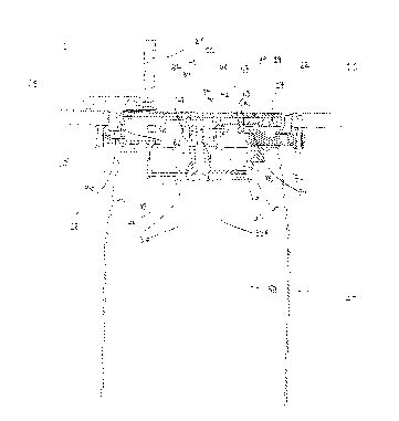
The internal elements of the embodiment of the invention depicted in
the accompanying FIGS. 1-5 and the interrelationship of those elements are
shown
in accompanying FIGS. 6-15. As particularly shown in the assembly view of FIG.
6
and in the cross-sectional view of FIG. 8, the upper surface of the platen 17
has
affixed thereon a transition pad 39 that preferably is constructed so to
fixedly
receive an undersurface of the abrasive sheet 19. For example, the transition
pad
39 may have hooks that detachably yet securely mate with loops on the
undersurface of the abrasive sheet 19, or the transition pad 39 may detachably
yet
securely mate with an adhesive compound resident on the undersurface of the
abrasive sheet 19.
As best shown in FIGS. 8 and 11, the undersurface of the platen 17
includes an inner cylindrical raised ring 41 and an outer cylindrical raised
ring 43,
lr
CA 02260571 1999-O1-26
and the inner and outer raised rings 41 and 43 are concentric. The platen 17
further includes three bores 25 defined entirely through the platen 17 within
inner
raised ring 41.
The abrading platen 17 is connected to a platen support 47. The
platen support 47 is best shown in FIGS. 9 and 10 and includes sloping sides
48 and
is generally in the shape of a frustum of a cone. The platen support 47
includes a
circular, raised outer rim 49 and a central cylindrical bore 50, and the walls
of the
bore 50 are defined by a bearing 52 so that a shaft seated within the bore 50
may
rotate therein with a reduced level of friction. Platen support 47 further
includes
three threaded bores 54 defined in a pattern matching that of bores 45 through
the
platen 17. As illustrated in FIG. 8, the space defined within the rim 49 of
the platen
support 47 is such that a portion of the inner ring 41 projecting from the
undersurface of the platen 17 seats within rim 49. When seated in that
fashion,
bores 45 through platen 17 align with threaded bores 54 of the platen support
47,
and threaded fasteners disposed through the aligned bores fasten the platen 17
to
the platen support in device 10. Connected in that arrangement, the central
axis of
bore 50 of the platen support 47 preferably is substantially coincident with
the
center point of platen 17.
Sanding device 10 further includes a transmission linking movement
of a motor shaft 56 of a motor 58, mounted within housing 14, to the platen
17. In
order to mount the platen 17 and its attached platen support 47 for rotation
about a
point and relative to the upper surface 20 of the worktable 15, the
transmission
includes an intermediate member in the form of a fan wheel 60. As best
illustrated
in FIG. 8 and in isolation in FIG. 16, fan wheel 60 includes a central hub 62
from
18
CA 02260571 1999-O1-26
(.
which extend laterally several fan vanes 64. The fan vanes 64 are partially
supported by a disk-shaped element 66 which also radiates outward from central
hub 62. A generally cylindrical spindle 68 projects from the central hub 62 of
the
fan wheel 60, and the hub 62 and spindle 68 includes a stepped central bore 70
having a lower portion 70A, an upper portion 70B of reduced cross-sectional
diameter relative to the lower portion, and a rim 72 defined by the transition
from
the lower portion 70A to the upper portion 70B of the central bore 70. The
upper
and lower portions 70B and 70A share an identical central axis. As further
described below, bore 70 accepts the elongate cylindrical motor shaft 56 of
the motor
58, and the rotation of the shaft 56 is imparted to the fan wheel 60.
As indicated in particular in FIGS. 6 and 8, sanding device 10
includes motor 58 mounted within housing 14 so that the rotatable motor shaft
56 is
oriented upward and toward platen 17. Motor shaft 56 may have a configuration
that corresponds to the central bore 70 of the fan wheel 60. Thus, motor shaft
56
may have a stepped cylindrical exterior configuration that will closely
conform to
the separate upper and lower portions 70A and 70B, respectively of central
bore 70.
The combined rotational and orbital motions of platen 17 are provided
by the configuration hub 60. As best indicated in FIG. 8, the central axis of
the bore
70 in the hub 60 is offset from the central axis of the spindle 68. The
arrangement
of the upper portion 70B of bore 70 in spindle 68 is represented in FIG. 15,
which is
a view looking downward onto spindle 68 of the hub 60 as the hub 60 is
oriented in
FIG. 8. The spindle 68 of the fan wheel is disposed within the central bore 50
of the
platen support 47 which in turn is secured to the undersurface of the platen
17.
The platen support 47 is secured to spindle 68 by washer 74 and threaded
fastener
19
CA 02260571 1999-O1-26
r
76, which is disposed through washer 74 and is threadedly secured into upper
portion 56A of motor shaft 56, which is correspondingly threaded to accept
fastener
76. Washer 74 is sized so as to overlap the bearing 52 and, when secured to
spindle
68, prevents platen support 47 from being removed from spindle 68. Thus, it
will be
understood that the central axis of the spindle 68, which defines the axis of
rotation
of the platen 17, is offset from the axis of rotation of the spindle 68, which
coincides
with the central axis of the motor shaft 56. Thus, the axis rotation of the
platen 17
is caused to orbit about the axis of rotation of the fan wheel 60, and the
platen
support 47 and the platen 17 also may rotate about the central axis of spindle
68 on
bearings 52. The combination of the simultaneous rotational and orbital
motions of
the platen 17 results in eccentric rotation of the platen 17 about the central
axis of
the motor shaft 56. Thus, if the platen 17 were allowed to freely rotate
(i.e., absent
friction) as it orbits, its rotational rate (i.e., revolutions/minute) would
eventually
reach its orbital rate (orbits/minute), and the angular directions of rotation
and
revolution would be the same (i.e., clockwise or counterclockwise).
To prevent the platen 17 from either stalling or reaching too great a
rate of rotation, a positive drive feature may be provided in the apparatus 10
to
impart positive rotational motion to the platen 17 during operation. The above-
described outer raised ring 43 may be considered a first drive member of the
positive drive feature. As shown in particular in FIG. 11, the underside of
platen 17
includes a resilient ring 80 mounted on the outer perimeter of outer raised
ring 43.
Resilient ring 80 is therefore centered on the axis formed by the central axis
of
spindle 68, as is described above. Resilient ring 80 may be formed from an
elastic
rubber, plastic, or another similarly resilient material, and may be seated in
a
CA 02260571 1999-O1-26
trough 82 on the outer perimeter of outer raised ring 43. The circumference of
resilient ring 80 is preferably slightly smaller than that of trough 82, and,
as such,
resilient ring 80 may be fitted into trough 82 and held there under elastic
tension
without the need for additional adhesives or other fastening means and so that
the
ring 80 experiences little or no independent rotation or slippage relative to
trough
82 during operation.
As shown in FIG. 6, the positive drive feature further includes a
second drive member in the form of a rigid ring 84 that is mounted to a
mounting
member 86 portion of the housing 14. A top view of the mounting member 86 and
the rigid ring 84 attached to the mounting member 86 by fasteners 88 is shown
in
FIG. 12. As shown in particular in FIG. 12, the rigid ring 84 is fixedly
mounted on a
surface of the mounting member 86 so that the rigid ring 84 leads into an
opening
90 in the mounting member 86. The opening 90 is centered about the axis of
motor
shaft 56, and the rigid ring 84 is generally concentric about an axis of the
motor
shaft 56. As shown in particular in FIG. 13, the inner circumference of rigid
ring 84
is greater than the outer circumference of outer raised ring 43. When the
device 10
is assembled, ring 43 is nested within the interior of rigid ring 84. As such,
the two
rings 43 and 84 lie substantially in a single plane. However, it will be
understood
that the central axes of the two rings 43 and 84 are not coincident because
their
central axes are offset by the distance by which the axis of spindle 68 is
offset from
the central axis of the motor shaft 56. Such offset is sized so that at least
one point
on the exposed surface of resilient ring 80 contacts at least one point along
the inner
circumference of the rigid ring 84 at all times. As such, when the device 10
is in
operation and the motor shaft 56 is rotating, fan wheel 60 rotates along with
motor
'? 1
CA 02260571 1999-O1-26
shaft 56 and platen 17 orbits on spindle 68 about the axis of rotation of the
motor
shaft 56. When disc 17 orbits, ring 43 and its resilient ring 80 are caused to
roll in
an orbit about the inner circumference of the rigid ring 84. The frictional
interaction between rigid ring 84 and resilient ring 80 urges the ring 43 (and
thus
the platen 17 attached thereto) to rotate in a direction of angular movement
that is
opposite to the direction of angular movement in which the platen 17 would
rotate if
it were able to freely rotate as it was caused to orbit through its eccentric
linkage
with the motor shaft 56. Only if the frictional interaction between the
resilient ring
80 on the outer circumference of the ring 43 and the inner circumference of
the rigid
ring 84 is overcome, and a slippage in the relative rolling motion of the two
rings 43
and 84 occurs, will the rotation of the abrading platen 17 set up by the
positive drive
feature be retarded.
Although a resilient ring 80 is included in the present embodiment, it
will be understood that if rings 43 and 84 are constructed of appropriate
materials
such a resilient ring 80 may not be needed to provide adequate frictional
interaction
between the rings 43 and 84. For example, one of the rings may be constructed
of a
hard rubber material that frictionally contacts the remaining ring, or both
rings 43
and 84 may be constructed of the hard rubber material.
An example of the relative movement of the rings 43 and 84 as the
motor shaft 56 rotates is provided in FIG. 13, which is a view looking
downward
onto the motor, which would be disposed beneath the plane of the paper. For
clarity, FIG. 13 excludes resilient ring 80 from the outer perimeter of ring
43. As
the motor shaft rotates in a clockwise direction, the outer circumference 91
of the
ring 43 rolls relative to the inner circumference 92 of the ring 84 in the
clockwise
CA 02260571 1999-O1-26
angular direction of the external arrow. This rolling motion causes the ring
43 to
rotate in the opposite angular direction (counterclockwise), indicated by the
internal
arrow.
It will be understood that in certain conditions of use sufficient force
may be applied to the surface of the platen 17 to upset the relative rolling
motion of
the two rings 43 and 84 and cause ring 43 to slip relative to ring 84. It will
further
be understood that the threshold force at which such slippage between rings 43
and
84 occurs can be increased, or such slippage possibly may be entirely
prevented, by
excluding resilient ring 80 and, instead, providing the outer circumference
9lof the
ring 43 and the inner circumference 92 of the rigid ring 84 with corresponding
sets
of geared teeth. As such, the teeth on ring 43 would be caused to interlock
with the
teeth on the rigid ring 84 and the ring 43 would orbit about the inner
circumference
of the rigid ring 84. In such an embodiment (not shown), the mechanical
linkage
provided by the intermeshing teeth would have to be overcome before any
slippage
would occur between the two rings 43 and 84. Other alternate arrangement for
providing positive rotation of the platen 17 as the motor shaft 56 rotates
will be
apparent to those of ordinary skill in the art upon consideration of the
present
description of the invention.
The present embodiment 10 additionally may incorporate a dust
collection feature. As indicated in FIG. 8, the fan wheel 60 is nested within
a
cylindrical air guide cylinder 96 that defines the walls of an air guide
cavity 98 that
is in communication with the upper surface 20 of the work table 15. The fan
wheel
GO is provided with a plurality of radially emanating vanes G4. In operation,
the fan
wheel 64 rotates along with the motor shaft 56, and the vanes 64 create a
partial
'? 3
CA 02260571 1999-O1-26
vacuum within the air guide cavity 98 by forcing air within the air guide
cavity 98
out through exhaust port 100, which communicates the air guide cavity 98 with
the
atmosphere exterior to the housing 14. Dust and other abraded matter from the
abrading process, pulled to the edge of the abrading platen 17 by centrifugal
force,
is drawn by the partial vacuum into the housing and into the air guide cavity
98 as
indicated generally by the arrow in FIG. 8, and is expelled through the
exhaust port
100. It will be understood that the exhaust port 100 optionally may be
connected to
a dust collection device or chamber as are known in the art as a means to
collect the
dust.
The oscillation of the abrading platen 17 may create a vibration force.
Accordingly, as shown in particular in FIG. 14, one or more counterbalance
weights
may be mounted as needed on the fan wheel 60, or on other elements of the
device
10, to counteract the vibrations. In the present embodiment, two weights 102
are
shown positioned between vanes 64 on the surface of the fan wheel 60. In one
manner to counteract vibrational forces, the weights may be symmetrically
disposed
about a line connecting the axes of spindle 68 and motor shaft 56 as is
indicated in
FIG. 14.
Those of ordinary skill in the art will, of course, appreciate that
various changes in the details, materials and arrangements of parts which have
been herein described and illustrated in order to explain the nature of the
invention
may be made by those skilled in the art within the principle and scope of the
invention as expressed in the appended claims.
24