Language selection

Search

Patent 2260979 Summary

Third-party information liability

Some of the information on this Web page has been provided by external sources. The Government of Canada is not responsible for the accuracy, reliability or currency of the information supplied by external sources. Users wishing to rely upon this information should consult directly with the source of the information. Content provided by external sources is not subject to official languages, privacy and accessibility requirements.

Claims and Abstract availability

Any discrepancies in the text and image of the Claims and Abstract are due to differing posting times. Text of the Claims and Abstract are posted:

  • At the time the application is open to public inspection;
  • At the time of issue of the patent (grant).
(12) Patent Application: (11) CA 2260979
(54) English Title: ARRANGEMENT OF A SCRAP CUTTER FOR THE TRANSPORTATION, ASSEMBLY AND DISMANTLING THEREOF, AND METHOD OF ASSEMBLING SAID ARRANGEMENT
(54) French Title: AGENCEMENT D'UNE CISAILLE A RIBLONS PERMETTANT DE LA TRANSPORTER, DE LA MONTER ET DE LA DEMONTER ET PROCEDE DE REALISATION DE CET AGENCEMENT
Status: Withdrawn
Bibliographic Data
(51) International Patent Classification (IPC):
  • B23D 31/00 (2006.01)
  • B26D 07/00 (2006.01)
  • B30B 09/32 (2006.01)
(72) Inventors :
  • SCHAAF, MICHAEL (Germany)
  • POHL, PETER (Germany)
  • KNUFMANN, HEINRICH (Germany)
(73) Owners :
  • SVEDALA LINDEMANN GMBH
(71) Applicants :
  • SVEDALA LINDEMANN GMBH (Germany)
(74) Agent: GOWLING WLG (CANADA) LLP
(74) Associate agent:
(45) Issued:
(86) PCT Filing Date: 1997-01-17
(87) Open to Public Inspection: 1997-07-24
Examination requested: 1999-01-13
Availability of licence: N/A
Dedicated to the Public: N/A
(25) Language of filing: English

Patent Cooperation Treaty (PCT): Yes
(86) PCT Filing Number: PCT/DE1997/000077
(87) International Publication Number: DE1997000077
(85) National Entry: 1999-01-13

(30) Application Priority Data:
Application No. Country/Territory Date
196 01 735.1 (Germany) 1996-01-19

Abstracts

English Abstract


In order to reduce assembly and dismantling times whilst retaining the
properties of mass-produced components, the invention proposes a scrap cutter
transport unit with a base frame (1) for accommodating assemblies both in
their transportation and their operating states. During transportation, the
transport unit accommodates the cutter stand (2) in the removed state so that
it can pivot about a point (3). A second transport unit is formed by the press
frame which comprises auxiliary supports for transportation purposes.


French Abstract

L'invention concerne une cisaille à riblons pour laquelle, afin de parvenir à des temps de montage et de démontage plus courts, sans altérer les propriétés d'éléments constitutifs produits en série, il est prévu de réaliser une unité de transport avec un cadre de base (1) destiné à recevoir des sous-groupes, que ce soit à l'état prêt au travail ou à l'état prêt au fonctionnement. Pendant le transport, cette unité de transport reçoit le support (2) de cisaille à l'état déposé, afin qu'il puisse pivoter autour d'un point d'appui (3). Une autre unité de transport formée par le bâti de presse présente des supports auxiliaires pour le bâti port.

Claims

Note: Claims are shown in the official language in which they were submitted.

Claims
1. Mobile scrap cutter comprising at least two preassembled transport units which
comprise the following components: a base frame (1) with spring elements (10) and
support members (12), a cutter stand (2) with a cutter bar carriage, a press bed (4) with a
slider cylinder (5) and a slider (6), a hydraulic drive unit (16) with accessories, such as
hydraulic lines (18), an oil cooler (17) and a control box (19), characterized in that one
of the transport units forms the base frame (1) which receives the components during
transport as well as during operation, wherein during the transport the cutter stand (2) is
laid down by pivoting the cutter stand about a pivot point (3), and that the other transport
unit is formed by the press bed (4) which is provided with auxiliary support members
(11) for the transport.
2. The mobile scrap cutter of claim 1, characterized in that the slider cylinder (5)
together with the slider plate (6) is laid down on the transport unit which comprises the
base frame (1).
3. The mobile scrap cutter of claims 1 or 2, characterized in that the additional
components, such as the hydraulic drive unit (16) with the accessories, such as the oil
cooler (17), the hydraulic lines (18) and the control box (19), are permanently mounted or
installed on the base frame (1).
4. The mobile scrap cutter of claim 1, characterized in that the cutter stand (2)
further comprises a swivel bearing (7), the spring element (10) and a support bolt (8)
which is used during the transport.
5. The mobile scrap cutter of claim 1, characterized in that the spring elements (10)
are secured during transport by clamping means.
-9-

6. The mobile scrap cutter of claim 1, characterized in that the base frame (1)
comprises permanently mounted support members (12) for the press bed (4).
7. The mobile scrap cutter of claim 6, characterized in that the support members(12) are split and are in part arranged on the press bed (4).
8. The mobile scrap cutter of claims 6 or 7, characterized in that the support
members (12) are provided with insertion guides (not shown) for mounting.
9. The mobile scrap cutter of claims 5 and 6, characterized in that the spring
elements (10) are fixed in place during transport through the support members (12).
10. The mobile scrap cutter of claim 1, characterized in that the cutter stand (2)
forms a separate transport unit.
11. The mobile scrap cutter of claim 1, characterized in that the press bed (4) is
completely preassembled without the lateral pressure cylinder (13).
12. The mobile scrap cutter of claim 1, characterized in that there are providedsupport cables (not shown) which are matched to the load distribution.
13. The mobile scrap cutter of claims 1 and 9, characterized in that the hydraulic
lines (18) comprise means for draining and sealing.
14. Method for assembling the mobile scrap cutter of claim 1, characterized by the
following steps:
-10-

- Lifting the base frame (1) including the superstructure from the transport means
and placing the base frame (1) on the prepared ground,
- Raising the cutter stand (2) by pivoting the cutter stand (2) about the pivot point
(3) via the swivel bearing (7) and placing the cutter stand (2) on the spring elements (10),
- Pulling out the support bolt (8),
- Releasing the clamping means of the spring elements (10) of the cutter stand (2),
- Lifting and removing the slider cylinder (5) and the slider plate (6) from the base
frame (1),
- Lifting the press bed (4) from the transport means and placing the press bed (4)
onto the support members (12) and connecting the split support members (12) to each
other,
- Releasing the clamping means of the spring elements (10) of the press bed (4)
which were secured for transport.
- Connecting the press bed (4) to the cutter stand (2),
- Installing the cutter and the stamping rail,
- Lifting the slider cylinder (5) including the slider plate (6) in position relative to
the press bed (4) and the rear support member (12),
- Installing the lateral pressure cylinder (13),
-11-

- Providing the hydraulic and electrical connections,
- Filling the hydraulic oil.
-12-

Description

Note: Descriptions are shown in the official language in which they were submitted.


~ CA 02260979 1999-01-13
ARRANGEMENT OF A SCRAP CUTTER FOR THE TRANSPORTATION, ASSEMBLY
AND DISMANTLING THEREOF, AND METHOD OF ASSEMBLING SAID ARRANGEMENT
FIELD OF THE TECHNOLOGY
The invention relates to a mobile scrap cutter and to a method for assembling and
disassembling the same, so that the scrap cutter can be moved cost-effectively to and used
at the respective operating site to cut scrap.
STATE OF THE rECHNOLOGY
Mobile scrap cutters known in the art are typically divided into two groups:
In the first group, a functional unit is perrn~n~ontly mounted, for example, on an
automobile, e.g. a truck, and is ready for use and can be operated at any time; in the
second group, a folded-up unit is placed on a flatbed transport unit and has to be
re~ccembled at the operating site before the unit fully functional. Conventional scrap
cuners in the second group are typically folded up by rotating the cutter stand with
respect to the press bed or vice versa.
It is difficult to secure the components of this type of scrap cutter in place during
transport and during the operation.

CA 02260979 1999-01-13
DESCRIPTION OF THE rNVENTION
It is the object of the invention to provide a mobile scrap cutter which overcomes the
above problem and can be easily transported. The scrap cutter of the invention has at least
two preassembled transport units which include the following components: a base frame
with spring elements and support members, a cutter stand with a cutter bar carriage, a
press bed with a slider cylinder and a slider, a hydraulic drive unit with accessories, such
as hydraulic lines and an oil cooler, and a control box. It is another object of the invention
to provide a method for assembling and disassembling the scrap cutter within a short time
and to employ mass-produced components adapted for use in conventional permanently
installed scrap cutters.
The object is solved in that one of the transport units forms the base frame and holds the
components during transport as well as during the operation. During transport, the cutter
stand is laid down by pivoting the cutter stand about a pivot point. The other transport
unit is formed by the press bed which has auxiliary support members for transport.
Additional embodiments of the invention are described in the claims 2 to 13.
The mobile scrap cutter can be assembled within a short time by using the assembly
method described in claim 14. The scrap cutter can be disassembled by reversing the
order of the assembly steps when the scrap cutter is to be transported to another operating
site.
The advantages of the scrap cutter of the invention can be summarized as follows:
- An investment decision about an efficient mass-produced scrap cutter can
be made quickly and planning can commence before a decision about the
operating site is made; no costly machine foundations are required,

CA 02260979 1999-01-13
- Short assembly and start-up times,
- Convenient transfer of the scrap cutter to another site,
- Retaining the advantages of a stationary scrap cutter.
The invention will now be described in detail based on a specific embodiment.
BRIEF DESCRIPTION OF THE DRAWINGS
The drawings show in:
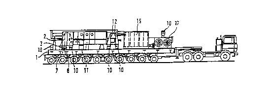
Fig. 1 a a side view of the transport unit with the base frame and the transport
means,
Fig. 1 b a top view of the transport unit of Fig. I a without the transport means,
Fig. 1c a side Yiew of the transport unit with the press bed and the transportmeans~
Fig. 1 d a front view of the transport unit of Fig. I c without the transport means,
Fig. 2a a side view of the scrap cutter in the operating position, and
Fig. 2b a front view of the scrap cutter of Fig. 2a.

CA 02260979 1999-01-13
BEST MODE FOR CARRYING OUT THE INVENTION
The ready-to-operate scrap cutter has a cutter stand 2 which is mounted on a base frame I
with the help of spring elements 10 and further includes a slider cylinder 5 and a slider
plate 6, a press bed 4 with a lateral pressure cylinder 13, a hydraulic drive unit 16 with an
oil cooler 17 and hydraulic lines 18 and a control box.
Referring now to Figs. la, b, the arrangement of the scrap cutter of the invention forms a
first transport unit which includes the base frame I and the spring elements 10 and
support members 12 adapted to receive the following components: the cutter stand 2 with
the cutter bar carriage (not shown), the slider cvlinder 5 and the slider plate 6 both in the
transport position and in the operating position and the following permanently mounted
components: the hydraulic drive unit 16 with the hydraulic lines 18, the oil cooler 17 and
the control box 19. During transport, the cutter stand 2 is lowered on the base frame I by
pivoting the cutter stand 2 about a pivot point 3 via a swivel bearing 7 which is located on
the cutter stand 2 together with the spring elements 10 and a support bolt 8. The slider
cylinder 5 and the slider plate 6 are also set down on the base frame I .
The spring elements 10 which support the cutter stand 2 and the press bed 4 on the base
frame I in the operating position (Fig. 2), are secured during transport by clamping means
(not shown).
The base frame I has permanently mounted support members 12 for supporting the press
bed 4 which are split and in part arranged on the press bed 4 (Fig. Ic, 2a).
.. . , . . .. ~ .

CA 02260979 1999-01-13
According to Fig. lc, the second transport unit is formed by the press bed 4 (which is
provided with a protective cover) which is provided with auxiliary support members 1 1
for transport and which is completely preassembled except ~or the lateral pressure
cylinder 13.
The arrangement described above and consisting of the two units is advantageously
transported on a semitrailer truck (e.g. a trailer combination with preferably 8 to 10
axles). In special situations, it can be advantageous to include in the first transport unit
only the base frame 1 and the cutter stand 2 which is lowered by pivoting about the pivot
point 3, and those components which are perrnanently installed on the base frame 1, e.g.
the hydraulic drive unit 16 (which is also provided with a protective cover) with
accessories, including the oil cooler 17 and the hydraulic lines 18, and to transport the
slider cylinder 5 with the slider plate 6 separately. According to claim 10, the cutter stand
2 can also be transported separately.
Support cables (not shown) ensure that the load is distributed evenly during transport.
The permanently installed hydraulic lines 18 of which not all are shown, have adapter
means for draining, sealing and/or connecting the lines.
INDUSTRIAL APPLICABILITY
The arrangement of the invention simplifies assembly and enables unexpectedly short
assembly times of at most two days, if the following inventive steps are followed:
. _

CA 02260979 1999-01-13
- The base frame 1 including the superstructure is lifted from the transport means
and set down on the prepared ground which advantageously does not have to be a
conventional foundation,
- The cutter stand 2 is raised by pivoting the cutter stand 2 about the pivot point 3
via the swivel bearing 7 so as to rest on the spring elements 10 which are still secured
with the clamping means,
- The support bolt is pulled out,
- The clamping means for the spring elements 10 of the cutter stand 2 which weresecured for transport, are released,
- The slider cylinder S and the slider plate 6 are lifted and removed from the base
frame 1,
- The press bed 4 is lifted from the transport means and set down on the supportmember 12, and the split support members 12 which have insertion guides for
positioning, are connected to each other,
- The clamping means of the spring elements 10 of the press bed 4 which were
secured for transport, are released,
- The press bed 4 is connected to the cutter stand 2,
- The cutter and the stamping rail are installed,
--6--
. _................................................ . ~.. ....

CA 02260979 1999-01-13
- The slider cylinder S including the slider plate 6 are raised into the proper position
relative to the press bed 4 and the rear support member 12,
- The lateral pressure cylinder 13 is installed,
- The hydraulic and electrical lines are connected, wherein this assembly step is
facilitated in that
* the limit switch is already installed on the slider plate 6,
* the control box 19 with the electrical components has non-interchangeable
connectors, and
* the hydraulic lines 18 also include the adapter means for draining and sealing,
- The hydraulic oil which is supplied by an tanker truck accompanying the transport
unit, is filled, wherein the hydraulic section is located above a collection pan (not shown)
adapted to collect any leaking fluid.
._

CA 02260979 1999-01-13
~ist of reference numerals
base frame
2 = cutter stand
3 = pivot point
4 = press bed
S = slider cylinder
6 = slider plate
7 = swivel bearing
8 = support bolt
10 = spring element
11 = auxiliary supports
12 = support members
13 = lateral pressure cylinder
16 = hydraulic drive unit
17 = oil cooler
18 = hydraulic lines
19 = control box

Representative Drawing
A single figure which represents the drawing illustrating the invention.
Administrative Status

2024-08-01:As part of the Next Generation Patents (NGP) transition, the Canadian Patents Database (CPD) now contains a more detailed Event History, which replicates the Event Log of our new back-office solution.

Please note that "Inactive:" events refers to events no longer in use in our new back-office solution.

For a clearer understanding of the status of the application/patent presented on this page, the site Disclaimer , as well as the definitions for Patent , Event History , Maintenance Fee  and Payment History  should be consulted.

Event History

Description Date
Inactive: IPC from MCD 2006-03-12
Inactive: Office letter 2001-03-19
Inactive: Withdraw application 2001-03-08
Inactive: Approved for allowance (AFA) 2001-01-18
Deemed Abandoned - Failure to Respond to Maintenance Fee Notice 2001-01-17
Inactive: Entity size changed 2000-02-09
Inactive: Correspondence - Formalities 2000-01-28
Inactive: Office letter 2000-01-17
Inactive: First IPC assigned 1999-03-23
Inactive: IPC assigned 1999-03-23
Classification Modified 1999-03-23
Inactive: Acknowledgment of national entry - RFE 1999-03-10
Application Received - PCT 1999-03-05
All Requirements for Examination Determined Compliant 1999-01-13
Request for Examination Requirements Determined Compliant 1999-01-13
Application Published (Open to Public Inspection) 1997-07-24

Abandonment History

Abandonment Date Reason Reinstatement Date
2001-01-17

Maintenance Fee

The last payment was received on 1999-12-23

Note : If the full payment has not been received on or before the date indicated, a further fee may be required which may be one of the following

  • the reinstatement fee;
  • the late payment fee; or
  • additional fee to reverse deemed expiry.

Patent fees are adjusted on the 1st of January every year. The amounts above are the current amounts if received by December 31 of the current year.
Please refer to the CIPO Patent Fees web page to see all current fee amounts.

Fee History

Fee Type Anniversary Year Due Date Paid Date
Basic national fee - standard 1999-01-13
Registration of a document 1999-01-13
MF (application, 2nd anniv.) - standard 02 1999-01-18 1999-01-13
Reinstatement (national entry) 1999-01-13
Request for examination - standard 1999-01-13
MF (application, 3rd anniv.) - small 03 2000-01-17 1999-12-23
Owners on Record

Note: Records showing the ownership history in alphabetical order.

Current Owners on Record
SVEDALA LINDEMANN GMBH
Past Owners on Record
HEINRICH KNUFMANN
MICHAEL SCHAAF
PETER POHL
Past Owners that do not appear in the "Owners on Record" listing will appear in other documentation within the application.
Documents

To view selected files, please enter reCAPTCHA code :


To view images, click a link in the Document Description column (Temporarily unavailable). To download the documents, select one or more checkboxes in the first column and then click the "Download Selected in PDF format (Zip Archive)" or the "Download Selected as Single PDF" button.

List of published and non-published patent-specific documents on the CPD .

If you have any difficulty accessing content, you can call the Client Service Centre at 1-866-997-1936 or send them an e-mail at CIPO Client Service Centre.

({010=All Documents, 020=As Filed, 030=As Open to Public Inspection, 040=At Issuance, 050=Examination, 060=Incoming Correspondence, 070=Miscellaneous, 080=Outgoing Correspondence, 090=Payment})


Document
Description 
Date
(yyyy-mm-dd) 
Number of pages   Size of Image (KB) 
Abstract 1999-01-12 1 69
Description 1999-01-12 8 205
Drawings 1999-01-12 2 47
Claims 1999-01-12 4 95
Representative drawing 1999-03-25 1 9
Notice of National Entry 1999-03-09 1 202
Courtesy - Certificate of registration (related document(s)) 1999-03-09 1 117
Courtesy - Abandonment Letter (Maintenance Fee) 2001-02-13 1 182
PCT 1999-01-12 12 368
Correspondence 2000-01-27 2 89
Correspondence 2001-03-07 1 28
Correspondence 2001-03-18 1 9
Fees 1999-12-22 2 60