Language selection

Search

Patent 2261175 Summary

Third-party information liability

Some of the information on this Web page has been provided by external sources. The Government of Canada is not responsible for the accuracy, reliability or currency of the information supplied by external sources. Users wishing to rely upon this information should consult directly with the source of the information. Content provided by external sources is not subject to official languages, privacy and accessibility requirements.

Claims and Abstract availability

Any discrepancies in the text and image of the Claims and Abstract are due to differing posting times. Text of the Claims and Abstract are posted:

  • At the time the application is open to public inspection;
  • At the time of issue of the patent (grant).
(12) Patent: (11) CA 2261175
(54) English Title: BELT-TYPE PARTICLEBOARD PRESS
(54) French Title: PRESSE DE TYPE A COURROIE POUR PANNEAUX DE PARTICULES
Status: Expired and beyond the Period of Reversal
Bibliographic Data
(51) International Patent Classification (IPC):
  • B27N 03/24 (2006.01)
(72) Inventors :
  • SEBASTIAN, LOTHAR (Germany)
  • WEISS, HORST (Germany)
  • SCHURMANN, KLAUS (Germany)
(73) Owners :
  • SIEMPELKAMP MASCHINEN- UND ANLAGENBAU GMBH & CO. KG
(71) Applicants :
  • SIEMPELKAMP MASCHINEN- UND ANLAGENBAU GMBH & CO. KG (Germany)
(74) Agent: BORDEN LADNER GERVAIS LLP
(74) Associate agent:
(45) Issued: 2003-01-07
(22) Filed Date: 1999-02-17
(41) Open to Public Inspection: 1999-08-18
Examination requested: 1999-05-27
Availability of licence: N/A
Dedicated to the Public: N/A
(25) Language of filing: English

Patent Cooperation Treaty (PCT): No

(30) Application Priority Data:
Application No. Country/Territory Date
198 06 707.0-44 (Germany) 1998-02-18

Abstracts

English Abstract

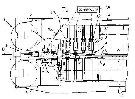
A press for pressing a mat into a thin panel has a press frame, upper and lower press plates on the frame, upper and lower press belts having confronting lower and upper stretches defining a press gap extending in a horizontal and longitudinal transport direction and respectively running below and above the upper and lower press plates, and upper and lower flexible intake plates juxtaposed respectively above and below upstream ends of the lower and upper stretches of the belts and defining therewith an intake mouth flaring upstream. An array of spaced fluid-powered actuators carried on the frame each have outer ends juxtaposed with one of the intake plates. Thermal insulation is provided between the actuator outer ends and the one intake plate to protect the actuators from the heat of the intake plates. Swivel joints, normally ball joints, are provided between the actuator outer ends and the one intake plate.


French Abstract

Une presse pour presser un mat dans un panneau mince comporte un bâti de presse, des plaques de presse supérieure et inférieure sur le bâti, des courroies de presse supérieure et inférieure qui comportent des allongements inférieur et supérieur opposés qui définissent un écart de presse, qui s'étend dans un sens de transport horizontal et longitudinal, et se trouvent respectivement en dessous et au-dessus des plaques de presse supérieure et inférieure, et des plaques d'introduction flexibles supérieure et inférieure qui sont juxtaposées, respectivement, au-dessus et en dessous d'extrémités amonts des allongements inférieur et supérieur des courroies et définissent conjointement une embouchure d'introduction qui s'évase en amont. Plusieurs actionneurs hydrauliques espacés, supportés sur le bâti, comportent chacun des extrémités extérieures juxtaposées avec une première des plaques d'introduction. Une isolation thermique est prévue entre les extrémités extérieures d'actionneur et la première plaque d'introduction pour protéger les actionneurs de la chaleur des plaques d'introduction. Des joints pivotants, normalement des joints sphériques, sont prévus entre les extrémités extérieures d'actionneur et la première plaque d'introduction.

Claims

Note: Claims are shown in the official language in which they were submitted.


WE CLAIM:
1. A press for pressing a mat into a thin panel,
the press comprising:
a press frame;
upper and lower press plates on the frame;
upper and lower press belts having confronting
lower and upper stretches defining a press gap extending in
a horizontal and longitudinal transport direction and
respectively running below and above the upper and lower
press plates;
upper and lower flexible intake plates juxtaposed
respectively above and below upstream ends of the lower and
upper stretches of the belts and defining therewith an
intake mouth flaring upstream;
an array of spaced fluid-powered actuators carried
on the frame and having outer ends juxtaposed with one of
the intake plates;
thermal insulation between the actuator outer ends
and the one intake plate; and
swivel joints between the actuator outer ends and
the one intake plate.
2. The press defined in claim 1 wherein the
actuators have inner ends juxtaposed with the frame, the
press further comprising
-10-

swivel joints between the actuator inner ends and
the frame.
3. The press defined in claim 1 wherein the
swivel joints are ball joints.
4. The press defined in claim 3 wherein each
swivel joint comprises
a shell fixed on the one intake plate and having a
part-spherical outer surface turned toward the respective
actuator outer end and a concentric part-spherical inner
surface turned away from the respective actuator outer end;
a seat formed on the respective actuator outer end
and complementarily engaging the shell outer surface; and
a head fixed on the respective actuator outer end
and having a surface riding on and complementary to the
shell inner surface.
5. The press defined in claim 4 wherein each
shell is formed with a throughgoing hole and the head has a
stem extending with lateral play through the hole and fixed
to the respective actuator outer end.
6. The press defined in claim 5 wherein the
thermal insulation includes insulating rings engaged between
the shell and the one intake plate.
-11-

7. The press defined in claim 6 wherein the rings
include upper and lower rings set into a rim of the shell,
the press further comprising
retaining blocks clamping the rings and shell rim
to the one intake plate.
8. The press defined in claim 5, further
comprising
a pressure plate between the insulating rings and
the shell.
9. The press defined in claim 8 wherein the rim
is made of steel and has a planar shape planar and sits
directly on the pressure plate.
10. The press defined in claim 8, further
comprising
respective other insulating rings surrounding the
pressure plates and engaged by the retaining blocks.
11. The press defined in claim 1 wherein the
actuators have inner ends juxtaposed with the frame, the
press further comprising
swivel joints between the actuator inner ends and
the frame and each including
a shell fixed on the frame and having a part-
spherical outer surface turned toward
the respective actuator inner end and a
-12-

concentric part-spherical inner surface
turned away from the respective actuator
inner end;
a seat formed on the respective actuator outer end
and complementarily engaging the shell
outer surface; and
a head fixed on the respective actuator outer end
and having a surface riding on and
complementary to the shell inner
surface;
respective crosspieces above each of the actuators
on the frame; and
respective tie fasteners extending vertically
through the crosspieces and having upper head ends bearing
downwardly on the respective crosspiece and lower ends
threaded into the respective shell.
12. The press defined in claim 1 wherein the one
intake plate is the upper intake plate and the frame
includes:
respective crosspieces above each of the
actuators; and
respective tie fasteners extending vertically
through the crosspieces and having upper head ends bearing
downwardly on the respective crosspieces and lower ends
threaded into the respective actuator.
-13-

Description

Note: Descriptions are shown in the official language in which they were submitted.


CA 02261175 1999-02-17
BELT-TYPE PARTICLEBOARD PRESS
SPECIFICATION
FIELD OF THE INVENTION
The present invention relates to a belt-type
continuous press. More particularly this invention concerns
such a press used for making particleboard.
BACKGROUND OF THE INVENTION
In the manufacture of particleboard, which term is
intended to cover chipboard and flakeboard, it is standard to
compress a relatively thick mat by a factor of eight or~more
into a hard panel. The mat is soft and comprised of~wood
particles mixed with a phenolic or other binder. The finished
workpiece is a hard board or panel with a pair of planar
faces.
Such a panel is produced in a continuous press
having a rigid press frame having vertically spaced upper and
lower parts defining a press gap that can extend some 30 m.
Upper and lower belts are spanned in the respective press
parts between respective upstream and downstream rollers, at
least one of which is driven to advance confronting upper and
lower stretches of the lower and upper belts longitudinally
through the press. Upper and lower press plates bear on the
lower and upper surfaces of the upper and lower stretches of
the lower and upper belts. Normally arrays of rollers run

CA 02261175 2002-03-20
between each belt and the respective supporting plate to
reduce friction.
The two belts typically are braced at an intake
mouth of the gap against flexible intake members or plates.
The mouth flares upstream. These intake members are
typically braced against the press frame by hydraulic
cylinders that are hooked to a common controller so that the
shape of the intake mouth can be set centrally.
In these arrangements, even when the actuators are
secured at their ends by cardan joints, the intake plates
and, hence, the belts passing over them, have perceptible
bends at the actuators. These bends create points of
excessive wear and subject the incoming mat to suddenly
varying compression.
OBJECTS OF THE INVENTION
It is therefore an object of the present invention
to provide an improved continuous belt-type mat press.
Another object is the provision of such an
improved continuous belt-type mat press which overcomes the
above-given disadvantages, that is which avoids the
perceptible bends at the actuators in the intake plates.
-2-

CA 02261175 1999-02-17
SUMMARY OF THE INVENTION
A press for pressing a mat into a thin panel has
according to the invention a press frame, upper and lower
press plates on the frame, upper and lower press belts having
confronting lower and upper stretches defining a press gap
extending in a horizontal and longitudinal transport direction
and respectively running below and above the upper and lower
press plates, and upper and lower flexible intake plates
juxtaposed respectively above and below upstream ends~of the
lower and upper stretches of the belts and defining therewith
an intake mouth flaring upstream. An array of spaced fluid-
powered actuators carried on the frame each have outer ends
juxtaposed with one of the intake plates. Thermal insulation
is provided between the actuator outer. ends and the one intake
plate to protect the actuators from the heat of the intake
plates. Swivel joints, normally ball joints, are provided
between the actuator outer ends and the one intake plate.
As a result the intake plates can bend in a uniform
curve. The actuators will not cause the curve to flex at each
attachment location since the connection between the actuators
and the one intake plate will be able to tip from side to side
and front to back as necessary to produce the desired intake-
mouth shape. As a result it is possible to produce workpieces
with thicknesses as small as 3 mm without the risk of the mats
tearing, even when the intake plates are substantially
parallel. In addition the use of such swivel joints allows
-3-

CA 02261175 1999-02-17
very flexible intake plates to be used that can be deformed to
virtually any desired shape.
Each swivel joint comprises according to the
invention a shell fixed on the one intake plate and having a
part-spherical outer surface turned toward the respective
actuator outer end and a concentric part-spherical inner
surface turned away from the respective actuator outer end, a
seat formed on the respective actuator outer end and
complementarily engaging the shell outer surface, and a head
fixed on the respective actuator outer end and having a
surface riding on and complementary to the shell inner
surface. The shells are each formed with a throughgoing hole
and the head has a stem extending with lateral play through
the hole and fixed to the respective actuator outer end.
The thermal insulation in accordance with the
invention includes insulating rings engaged between the shell
and the one intake plate. These insulating rings include
upper and lower rings set into a rim of the shell. Retaining
blocks clamp the rings and shell rim to the one intake plate.
A pressure plate is provided between the insulating rings and
the shell. The rim of the shell is steel and planar and sits
directly on the pressure plate. In addition respective other
insulating rings may surround the pressure plates and be
engaged by the retaining blocks.
Furthermore according to the invention the actuators
have inner ends juxtaposed with the frame. The press further
has swivel joints between the actuator inner ends and the
frame and each including a shell fixed on the frame and having
-4-

CA 02261175 1999-02-17
a part-spherical outer surface turned toward the respective
actuator inner end and a concentric part-spherical inner
surface turned away from the respective actuator inner end, a
seat formed on the respective actuator outer end and
complementarily engaging the shell outer surface, and a head
fixed on the respective actuator outer end and having a
surface riding on and complementary to the shell inner
surface. Respective crosspieces are provided above each of
the actuators on the frame and respective tie screws extending
vertically through the crosspieces have upper head ends
bearing downwardly on the respective crosspiece and lower ends
threaded into the respective shell.
Normally in accordance with the invention the one
intake plate is the upper intake plate, although it is within
the scope of the invention for both intake plates to be
provided with actuators according to the invention. In the
system with the actuators above the upper plate the frame
includes respective crosspieces above each of the actuators.
Respective tie screws extend vertically through the
crosspieces and have upper head ends bearing downwardly on the
respective crosspieces and lower ends threaded into the
respective actuator. If there are actuators for the lower
press plate instead of or in addition to those of the upper
plate, they are complementarily arranged.
_5_

CA 02261175 1999-02-17
BRIEF DESCRIPTION OF THE DRAWING
The above and other objects, features, and
advantages will become more readily apparent from the
following description, reference being made to the
accompanying drawing in which:
FIG. 1 is a partly diagrammatic side view
illustrating a press according to the invention;
FIG. 2 is a section taken along line II--II of
FIG. 1 showing a detail of the press; and
FIG. 3 is a view like FIG. 2 of an alternative press
in accordance with the invention.
SPECIFIC DESCRIPTION ,
As seen in FIGS. 1 and 2 a press 1 according to the
invention serves to compress a thick mat 2 of particles and
binder. It has a frame formed by a lower part 3 and an upper
part 4. A pair of endless stainless-steel belts 5 have
confronting lower and upper stretches riding over upper and
lower heated press platen 6 and 7 and flexible upper and lower
intake plates 8 and 9 to define a pressing gap 39 extending in
a horizontal mat transport direction D and having an intake
mouth E that opens upstream in the direction D and that is
flared against this direction D. Respective arrays of rollers
10 ride between the belts 5 and the plates 6-9 to allow the
belts 5 to move smoothly with little friction. The gap 39 is
-6-

CA 02261175 1999-02-17
basically subdivided into an upstream portion at the mouth E
where the mat 2 is compressed almost down to its finished
size, and a downstream portion in which the mat 2 is held at
this compressed size and heated to cure its binder. More
particularly, the press gap 39 starts at the intake mouth E
where in FIG. 1 it is relatively wide to accommodate the mat
2. A system 11 is provided for setting the width of the
upstream end of the mouth E and another system 12 is provided
for setting the shape of the belts 5 and plates 8 and 9
downstream along the intake mouth E.
According to the invention the system 12 is~
comprised of an array of heavy-duty double-acting hydraulic
cylinders 13 operated by a common controller 38 and spaced
apart in and transversely of the direction D, that is forming
at least two rows extending in the direction D. Each such
cylinder 13 has an upper end secured to a depending beam or
bar 37 of the upper press part 4 and a lower end bearing via a
ball-and-socket joint 14 and insulation 15 on the upper plate
8. Of course it would also be possible to use pneumatic
cylinders, the term "fluid" here being intended to cover gas
and liquid.
As better shown in FIG. 2 the joints 14 each
comprise a downwardly concave cup-shaped shell 16 having a
part-spherical upper surface 16' and a part-spherical lower
surface 16" concentric therewith. The lower end of the
actuator 13 is provided with a mounting plate 19 having a
part-spherical seat 20 complementary to the part-spherical
upper surface 16'. A head piece 17 has an upwardly directed

CA 02261175 2002-03-20
part-spherical surface complementary to and engaging the
surface 16" and a small-diameter stem 22 extending up through
a large-diameter hole 21 in the shell 16. A screw 23
extending coaxially through the stem 22 secures the head piece
17 to the plate 19. The lower edge of the shell 16 bears via
a pressure plate 24 and several insulating plates 25 on the
plate 8. Insulation 15 comprises insulating plates 25 and
insulating ring 27. The insulating ring 27 surrounding the
plates 24 and 25 is secured in place by a holding ring 26
which can be in several pieces. It is therefore possible for
the plate 8 to rock from front to back and from side to side
relative to the actuators 13 while these actuators 13 continue
to exert the desired downward pressure on the plate 8.
The actuators 13 are each connected to the bar 37 by
means of a crosspiece 34 that fits through a crosswise hole 36
in the bar and by long tie bolts 32 having lower ends screwed
into the upper side of the actuator 13. To this end the outer
ends of the crosspiece 34 are formed with vertically
throughgoing holes 33 and heads 35 bear on upper surfaces of
the crosspieces 34. Thus each actuator 13 is rigidly locked
to the bar 37, but the plate 8 can tip from side to side and
front to back relative to its lower end without putting any
significant lateral stress on the actuator 13.
In the arrangement of FIG. 3 a shell 16a
substantially identical to the shell 16 of FIGS. 1 and 2 has a
rim 28 engaged between lower and upper insulating rings 27 and
and captured under L-shaped holddown blocks 29 secured in
place by bolts 31. In addition the upper end of the housing
-g_

CA 02261175 2002-03-20
18 of the actuator 13 is provided with another such headpiece
17a engaged in another upwardly concave shell 16b whose part-
spherical lower face is slidable on a part-spherical seat 20a
of the housing 18 and which is secured in place by the tie
screws 32. A screw 23a extending through a stem 22a of the
headpiece 17a secures it to the housing 18 so that the upper
end of the actuator 13 can also swivel.
_g_

Representative Drawing
A single figure which represents the drawing illustrating the invention.
Administrative Status

2024-08-01:As part of the Next Generation Patents (NGP) transition, the Canadian Patents Database (CPD) now contains a more detailed Event History, which replicates the Event Log of our new back-office solution.

Please note that "Inactive:" events refers to events no longer in use in our new back-office solution.

For a clearer understanding of the status of the application/patent presented on this page, the site Disclaimer , as well as the definitions for Patent , Event History , Maintenance Fee  and Payment History  should be consulted.

Event History

Description Date
Time Limit for Reversal Expired 2014-02-18
Letter Sent 2013-02-18
Inactive: Late MF processed 2011-04-14
Letter Sent 2011-02-17
Inactive: Late MF processed 2008-03-13
Letter Sent 2008-02-18
Letter Sent 2003-09-11
Grant by Issuance 2003-01-07
Inactive: Cover page published 2003-01-06
Pre-grant 2002-10-29
Inactive: Final fee received 2002-10-29
Notice of Allowance is Issued 2002-07-16
Letter Sent 2002-07-16
Notice of Allowance is Issued 2002-07-16
Inactive: Approved for allowance (AFA) 2002-07-08
Amendment Received - Voluntary Amendment 2002-03-20
Inactive: S.30(2) Rules - Examiner requisition 2001-11-20
Application Published (Open to Public Inspection) 1999-08-18
Inactive: Cover page published 1999-08-17
Letter Sent 1999-06-28
All Requirements for Examination Determined Compliant 1999-05-27
Request for Examination Requirements Determined Compliant 1999-05-27
Request for Examination Received 1999-05-27
Inactive: IPC assigned 1999-03-24
Inactive: First IPC assigned 1999-03-24
Classification Modified 1999-03-24
Inactive: Inventor deleted 1999-03-08
Filing Requirements Determined Compliant 1999-03-08
Inactive: Filing certificate - No RFE (English) 1999-03-08
Application Received - Regular National 1999-03-08

Abandonment History

There is no abandonment history.

Maintenance Fee

The last payment was received on 2002-01-25

Note : If the full payment has not been received on or before the date indicated, a further fee may be required which may be one of the following

  • the reinstatement fee;
  • the late payment fee; or
  • additional fee to reverse deemed expiry.

Patent fees are adjusted on the 1st of January every year. The amounts above are the current amounts if received by December 31 of the current year.
Please refer to the CIPO Patent Fees web page to see all current fee amounts.

Owners on Record

Note: Records showing the ownership history in alphabetical order.

Current Owners on Record
SIEMPELKAMP MASCHINEN- UND ANLAGENBAU GMBH & CO. KG
Past Owners on Record
HORST WEISS
KLAUS SCHURMANN
LOTHAR SEBASTIAN
Past Owners that do not appear in the "Owners on Record" listing will appear in other documentation within the application.
Documents

To view selected files, please enter reCAPTCHA code :


To view images, click a link in the Document Description column. To download the documents, select one or more checkboxes in the first column and then click the "Download Selected in PDF format (Zip Archive)" or the "Download Selected as Single PDF" button.

List of published and non-published patent-specific documents on the CPD .

If you have any difficulty accessing content, you can call the Client Service Centre at 1-866-997-1936 or send them an e-mail at CIPO Client Service Centre.


Document
Description 
Date
(yyyy-mm-dd) 
Number of pages   Size of Image (KB) 
Abstract 1999-02-16 1 28
Description 1999-02-16 9 324
Drawings 1999-02-16 3 92
Claims 1999-02-16 5 118
Representative drawing 2002-12-03 1 20
Description 2002-03-19 9 322
Claims 2002-03-19 4 111
Drawings 2002-03-19 3 89
Representative drawing 1999-08-11 1 18
Courtesy - Certificate of registration (related document(s)) 1999-03-07 1 117
Filing Certificate (English) 1999-03-07 1 165
Acknowledgement of Request for Examination 1999-06-27 1 179
Reminder of maintenance fee due 2000-10-17 1 110
Commissioner's Notice - Application Found Allowable 2002-07-15 1 164
Late Payment Acknowledgement 2008-04-03 1 165
Maintenance Fee Notice 2008-03-30 1 172
Maintenance Fee Notice 2011-03-30 1 170
Late Payment Acknowledgement 2011-05-05 1 164
Maintenance Fee Notice 2013-04-01 1 171
Correspondence 2002-10-28 1 28