Note: Descriptions are shown in the official language in which they were submitted.
CA 02261318 2004-03-25
GAS SUPPLY DEVICE
BACKGROUND OF THE INVENTION
The present invention generally relates to a gas supply
assembly for an appliance powered by natural gas. The
invention also provides a method of assembling the
appliance.
Many domestic appliances are powered, at least in part,
by natural gas. This necessitates that the appliance be
provided with a gas supply assembly for connecting the
appliance to an external gas supply line and for feeding the
incoming natural gas to a burner assembly.
Various improvements of gas supply assemblies have been
made through the years. These improvements include the use
of a double-bead fitting such as found in U.S. Patent Nos.
4,871,199 issued October 3, 1989 and 5,573,285 issued
November. 12, 1996. Another improvement is the use of a
stake joint to join a gas carrying tube with a fitting
component. Examples of stake joints are found in U.S. Patent
Nos. 3,930,298 issued January 6, 1976, 3,977,710 issued
August 31, 1976 and 4,126,929 issued November 28, 1978.
Double-bead fittings and stake joints have helped to reduce
the number of parts required by the appliance, and reduced
the number of steps required to assemble the appliance.
Despite these improvements, however, there exists a
need in the art of appliance manufacturing to further
improve the gas supply assembly and the method of assembling
the appliances. It has been found that during installation,
excessive torque is often placed on parts comprising the gas
supply assembly. This excessive torque commonly results in
fractured parts or separated joints which would allow the
leakage of natural gas.
- 1 -
DOCSOTT: 293326\1
CA 02261318 1999-02-OS
1 Obviously, this condition is unacceptable and must be
2 corrected before completing the assembly process.
3 Repairing or replacing damaged parts, however, increases
4 both the total cost and assembly time of the appliances.
In addition, the installation process of a gas
6 supply assembly into the appliance is lengthy and
7 difficult. A number of factors contribute to this
8 problem. These factors include the lack of space within
9 the appliance to manipulate parts and tools, the
difficulty in positioning the gas supply assembly around
11 other appliance subsystems, and the difficulty in holding
12 one end of gas supply assembly while securing the other.
13 These difficulties also increase the total cost of the
14 appliance.
The present invention overcomes at least some of the
16 above-noted disadvantages of the related art by providing
17 a gas supply assembly for an appliance that makes the
18 assembling process easier and faster while minimizing the
19 number of damaged parts: This is accomplished by
providing a preshaped gas supply assembly that has
21 interlocking components to support and prevent the
22 rotation of the assembly during installation. The gas
23 supply assembly can be attached to a burner assembly
24 outside of the appliance where manipulation of the parts
is simple. The gas supply assembly is constructed of
26 lightweight parts that assist in reducing the overall
27 weight and shipping cost of the appliance.
28 BRIEF SUMMARY OF THE INVENTION
29 According to the present invention, a gas supply
assembly for an appliance includes a tube with a first
31 end and a second end. The tube is preshaped to fit
32 around appliance subsystems, thus enhancing the
33 installation of the gas supply assembly in the appliance.
34 The first end is provided with a first fitting and the
second end is provided with a second fitting, the second
2
CA 02261318 1999-02-OS
1 fitting having a second fitting shape. The assembly also
2 has a mounting bracket defining a bracket opening for
3 receiving the second fitting. The bracket opening has a
4 shape complementary to that of the second fitting shape
so that the mounting bracket and the second fitting
6 cooperate to substantially prohibit rotation of the tube.
7 The present invention also provides a method of
8 assembling an appliance having a cabinet. A tube
9 assembly includes a preformed tube shaped to fit around
objects in the cabinet, first fitting at a first end of
11 the tube and a second fitting at a second end of the
12 tube. The tube assembly is attached to a burner assembly
13 using the first fitting. The tube assembly and the
14 attached burner assembly are then inserted into the
cabinet so that a first portion of the second fitting
16 extends through an opening defined by the cabinet. The
17 burner assembly is then secured within the cabinet.
18 The present invention also provides a method of
19 assembling a gas supply device. A tube, having a first
end and a second end, is bent into a shape which enhances
21 installation of the device in an appliance. A first
22 fitting is attached to the first end of the tube. A
23 second fitting, defining a second fitting shape, is
24 attached to the second end of the tube. A mounting
bracket is provided for attaching the device to a
26 cabinet. The mounting bracket defines a bracket opening
27 for receiving the second fitting. The bracket opening
28 has a shape complementary to that of the second fitting
29 shape. The mounting bracket is placed on the second
fitting so that the second fitting shape and the bracket
31 opening shape cooperate to substantially prohibit
32 rotation of the tube relative to the second fitting. The
33 cabinet is provided with a receptor for receiving the
34 mounting bracket and preventing rotation of the mounting
bracket. Therefore, rotation of the device as a whole is
36 prevented to avoid damage to the device.
3
CA 02261318 1999-02-OS
1 BRIEF DESCRIPTION OF THE SEVERAL VIEWS OF THE DRAWING
2 These and further features of the present invention
3 will be apparent with reference to the following
4 description and drawings, wherein:
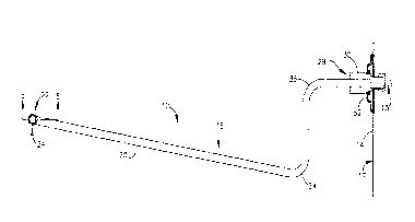
FIG. 1 is a partial cross sectional view of a gas
6 supply assembly according to the present invention;
7 FIG. 2 is a partial cross sectional view of the gas
8 supply assembly of FIG. 1 rotated 90 degrees;
9 FIG. 3 is a cross sectional view along the line 3--3
in FIG. 2;
11 FIG. 4 is a cross sectional view along the line 4--4
12 in FIG. 3; and
13 FIG. 5 is a cross sectional view along the line 5--5
14 in FIG. 1.
DETAILED DESCRIPTION OF THE INVENTION
16 In the detailed description which follows, identical
17 components have been given the same reference numerals,
18 and, in order to clearly and concisely illustrate present
19 invention, certain features may be shown in somewhat
schematic form.
21 Referring to FIGS. 1 and 2, the present invention
22 provides a gas supply assembly l0 for a gas powered
23 appliance. The illustrated appliance is a clothes dryer,
24 but other types of gas powered appliances are within the
scope of the present invention. The gas supply assembly
26 10 connects a burner assembly 11 that consumes natural
27 gas to an external gas supply line 13. The burner
28 assembly 11 includes a tube manifold 12 and other
29 components such as a gas valve, a gas burner, an igniter
and a burner mounting bracket 15.
31 The appliance includes a cabinet 17 having at least
32 one cabinet wall 14. The cabinet wall 14 is provided
33 with an opening 16 (FIG. 3) and, as will be discussed in
34 greater detail below, a part of the gas supply assembly
4
CA 02261318 2004-03-25
extends through the cabinet opening 16 (FIG. 3).
The gas supply assembly 10 includes a tube assembly 18
and a mounting bracket 52. The tube assembly includes a tube
20, a first or burner fitting 24 and a second or inlet
5 fitting 30. The tube assembly 18 parts are preferably made
of lightweight nonferrous material, such as aluminum, but
can be any other suitable material such as steel. Such a
tube 20 is resilient, but is also easily bent into a desired
shape and is flexible so that it will yield slightly during
10 installation. This makes manipulation of the gas supply
assembly 10 relatively effortless when the components are
positioned and secured in the appliance. The tube 20 is
fabricated with a series of bends 33, 34, and 35 in
predetermined locations and with predetermined angles. The
bends 33, 34 and 35 are provided to allow the gas supply
assembly 10 to extend through the interior of the appliance
from the gas supply line 13 to the burner assembly 11. Some
bends 33, 34 and 35 may also be required to guide the tube
around other components in the appliance. While the
illustrated tube has 3 bends, other quantities, locations,
and/or angles may be necessary for other appliances.
The tube 20 has a first end 22 provided with the burner
fitting 24. The burner fitting 24 is preferably a double-
bead fitting, but can be other suitable types of fittings.
U.S. Patent Nos. 4,871,199 issued October 3, 1989 and
5,573,285 issued November 12, 1996 both disclose double-bead
type fitting. The burner fitting 24 engages the burner
assembly 11 via the tube manifold 12, as best shown in
FIG. 2.
The tube 20 has a second end 28 provided with the inlet
fitting 30. The inlet fitting 30 is also made out
of lightweight nonferrous material, such as aluminum, but
can be any other suitable material. This type of material
makes the inlet fitting 30 easy to machine and manufacture,
- 5 -
DOCSOTT: 2933260
CA 02261318 2004-03-25
resulting in an economical product. The inlet fitting 30 is
preferably joined to the tube 20 using a stake joint 32
(FIG. 3), but can be joined by any suitable joint. Examples
of stake joints 32 are disclosed in U.S. Patent Nos.
3,930,298 issued January 6, 1976, 3,977,710 issued August
31, 1976 and 4,126,929 issued November 28, 1978.
Referring to FIG. 3, the inlet fitting 30 is shown in
cross section. The inlet fitting 30 is provided with a body
portion 36. The body portion 36 is preferably shaped so that
it may be grasped by a wrench. For example, a hex-shaped
body portion 36 will suffice. The inlet fitting 30 has a
front 40 at one end and a back 42 at the other end.
Extending from the front 40 is a first threaded portion 44
and a second threaded portion 46. The first threaded
portion 44 is sized for connection to the gas supply line 13
(FIG. 1) .
The inlet fitting 30 defines a passageway 50 extending
from the front 40 to the back 42. The tube 20, which is
preferably joined to the back of the inlet fitting 30,
communicates with the passageway 50 so that natural gas may
flow from the gas supply line, through the inlet fitting 30,
through the tube 20, to the burner assembly 11. As one
skilled in the art will appreciate, the tube 20 may
alternatively be joined to a side of the inlet fitting 30
and communicate with a passageway 50 originating in the
front 40 of the inlet fitting 30, turning in the inlet
fitting 30 and terminating in the side of the inlet fitting
where the tube 20 is connected to the inlet fitting 30.
With reference to FIGS. 3 and 4, the mounting bracket
30 52 defines a bracket opening 54. The bracket opening 54
is sized and shaped to receive the inlet fitting 30 so that
the mounting bracket 52 cooperates with a complimentary
inlet fitting shape 56. In this manner, the
mounting bracket 52 and the inlet fitting 30 cooperate
so as to minimize rotation of the tube 20. The
- 6 -
DOCSOTT: 293326\1
CA 02261318 1999-02-OS
1 interaction between the mounting bracket 52 and the inlet
2 fitting 30 also serves to support the tube 20 within the
3 appliance. The inlet fitting shape 56 is preferably
4 defined by the outer surface of the second threaded
portion 46, but may be defined by the body portion 36 or
6 the first threaded portion 44 with equivalent results.
7 Once received by the mounting bracket 52, the inlet
8 fitting 30 is secured to the mounting bracket 52. In the
9 preferred embodiment, this is accomplished by threadably
engaging a nut 60 on the second threaded portion 46. The
11 mounting bracket 52 is provided with a recess 62 in the
12 area around the bracket opening 54. The recess 62
13 accommodates the nut 60 allowing the mounting bracket 52
14 to be secured flush with the cabinet wall 14.
In order to be secured to the cabinet wall 14, the
16 mounting bracket 52 and the cabinet wall 14 are provided
17 with at least one screw hole. A screw 64, or
18 equivalently a bolt and nut combination, is used in
19 conjunction with the screw hole to secure the mounting
bracket 52 to the cabinet wall 14 (FIGS. 2 and 4). For
21 enhanced aligning and securing capability, the mounting
22 bracket 52 may be provided with projections 66,
23 preferably in the form of ridges along edges of the
24 mounting bracket 52. To receive the projections 66, the
cabinet wall 14 is provided with receptors 68. The
26 receptors 68 are preferably in the form of slots for
27 receiving the ridges. The projections 66 and receptors
28 68 cooperate to align the mounting bracket 52 and help to
29 retain the mounting bracket 52 in position. With the use
of projections 66 and receptors 68, the use of screws 64
31 to secure the mounting bracket 52 becomes optional.
32 This is because the resiliency of the components, namely
33 the tube 20 and the inlet fitting 30, will hold the
34 mounting bracket 52 in place once the burner assembly is
secured within the appliance. One skilled in the art
36 will appreciate that receptors 68 may be integrally
37 formed with the cabinet wall 14 or on a separate receptor
7
CA 02261318 1999-02-OS
1 plate (not shown) that is secured to the cabinet wall.
2 An appliance incorporating the gas supply assembly
3 10 according to the present invention may be assembled in
4 an easy and time efficient manner. Two alternative
assembly methods are contemplated.
6 The first assembly method begins with attaching the
7 tube assembly 18 to the burner assembly il by securing
8 the burner fitting 24 to the burner manifold 12. This
9 step is preferably performed outside the appliance
cabinet 17 where the parts are easily manipulated. Then,
11 the mounting bracket 52 is placed on the inlet fitting 30
12 so that the inlet fitting shape 56 is in cooperation with
13 the bracket opening 54. The mounting bracket 52 is then
14 secured to the inlet fitting 30 using the nut 60. Next,
the tube assembly 18, with the attached burner assembly
16 11 and mounting bracket 52; is inserted into the cabinet
17 17 so that the first threaded portion 44 extends through
18 the cabinet opening 16 and the burner mounting bracket 15
19 is adjacent a receiving point 72. Once the components
are inserted and positioned in the appliance, the burner
21 assembly 11 is secured within the appliance by attaching
22 the burner mounting bracket 15 to the receiving point
23 with screws 74 or the like. Finally, the mounting
24 bracket 52 is secured to the cabinet wall 14 with the
screws) 64 or aligning the projections 66 to be received
26 by the receptors 68, or both. It should be noted that
27 the projections 66 and the receptors 68 may already be
28 aligned as a result of the inserting and positioning
29 procedure. It should also be noted that the order of
many of the steps may be changed. For example, the
31 mounting bracket 52 may be secured to the inlet fitting
32 30 before the burner assembly 11 is secured to the tube
33 assembly 18.
34 The second assembly method also begins with
attaching the tube assembly 18 to the burner assembly 11
36 by securing the burner fitting 24 to the burner manifold
37 12. This step is preferably performed outside the
8
CA 02261318 1999-02-OS
1 appliance cabinet 17 where the parts are easily
2 manipulated. Next, the mounting bracket 52 is secured to
3 the cabinet wall 14 using the screws) 64 so that the
4 bracket opening 54 is aligned with and adjacent the
cabinet opening 16. At this point, the projections 66
6 should be engaged in the receptors 68, if the embodiment
7 using the projections 66 and receptors 68 is selected.
8 It should be noted that the step of attaching the tube
9 assembly 18 to the burner assembly 11 and the step of
securing the mounting bracket 52 may be conducted in an
11 opposite order with equivalent results. Next, the tube
12 assembly 18, with the attached burner assembly 11, is
13 inserted into the cabinet 17 so that the first threaded
14 portion 44 extends through the cabinet opening 16, the
inlet fitting shape 56 is in cooperation with the bracket
16 opening 54, and the burner mounting bracket is adjacent
17 the receiving point 72. Once the components are inserted
18 and positioned in the appliance, the burner assembly is
19 secured within the appliance by attaching the burner
mounting bracket 15 to the receiving point with screws 74
21 or the like. Finally, the mounting bracket 52 is secured
22 to the inlet fitting 30 by passing the nut 60 over the
23 first threaded portion 44 and through the cabinet opening
24 16, then by threadably engaging the nut 60 on the second
threaded portion 46. Should this assembly method
26 embodiment be employed, the cabinet opening 16 must be
27 large enough to accommodate the nut 60 and a tool to
28 tighten the but 60. One skilled in the art will
29 appreciate that the order of many of the foregoing steps
may be changed with equivalent results.
31 For a number of reasons, both of these methods
32 greatly assist in making the assembly of the appliance
33 easy and economical. A major reason is that the
34 components are assembled in locations where working on
the parts is simple. For example, the tube assembly 18
36 is attached to the burner assembly 11 outside the
37 appliance cabinet 17 rather than inside the cabinet 17
9
CA 02261318 1999-02-OS
1 where space is limited and manipulation of the parts and
2 tools is difficult. Another reason is that before the
3 inlet fitting 30 and mounting bracket 52, and the
4 mounting bracket 52 and cabinet wall 14, are permanently
secured, they all lock together with cooperating shapes
6 as to support and prevent rotation of the tube assembly
7 while the burner assembly 11 is being secured. Once the
8 burner assembly 11 is secured, the remaining parts may be
9 secured with little effort. Another reason is that the
selection of the tube 20 material adds flexibility to the
11 gas supply assembly 18. This allows for the easy
12 manipulation of the components during the positioning and
13 securing of the burner assembly 11 and inlet fitting
14 30/mounting bracket 52 combination.
Although particular embodiments of the invention
16 have been described in detail, it is understood that the
17 invention is not limited correspondingly in scope, but
18 includes all changes and modifications coming within the
19 spirit and terms of the claims appended hereto.