Note: Descriptions are shown in the official language in which they were submitted.
CA 02261431 1999-02-11
METHOD FOR ADAPTIVELY CONTROLLING
AMPLIFIER LINEARIZATION DEVICES
Field Of The Invention
The present invention relates generally to communication systems and, more
particularly, to linearized amplification devices used in wireless
communication systems.
Background Of The Related Art
Amplifiers used in mufti-channel applications, such as cellular radio and
Personal
Communication System (PCS) transceivers, typically produce output signals
having desired signals
and undesirable intermodulation products created by the amplifiers. While the
intermodulation
products may be at a very low level relative to the desired signals, the level
of intermodulation
products may be high enough to impair transmission or exceed some acceptable
threshold or standard.
The level of the intermodulation product created by the amplifiers is
determined, in part, by the
characteristics of the amplifiers, which is dependent on a variety of
parameters, such as temperature,
supply voltage, signal level, age, etc.
To reduce the level of the intermodulation products (i.e., linearize), the
amplifier can
be incorporated into a circuit having a linearizer. Various linearizers may be
employed to linearize
the amplifiers. Such linearizers incorporate well-known linearization
techniques, such as
feedforward, feedback, pre-distortion and post-distortion. Linearizing an
amplifier involves adjusting
the linearizers to match or track the characteristics of the amplifier being
linearized.
Adjusting the linearizers to match or track the characteristics of the
amplifier is
relatively straightforward under static conditions, e.g., constant
temperature, supply voltage, signal
level, etc., as is well known in the art. Under non-static conditions,
however, adjusting the linearizer
to match or track the characteristics of the amplifier is more complex. Each
time a parameter
affecting the characteristics of the amplifier changes, the linearizer would
need to be adjusted to
compensate.
There are two fundamentally different approaches to adjusting linearizers to
compensate for non-static conditions: open-loop and closed-loop control or
compensation. Open-
loop control involves measuring changes in the parameters affecting the
characteristics of the
amplifier (e.g., temperature), and using the measured parameter changes to
adjust the linearizer to
match or track the characteristics of the amplifier. The effectiveness of open-
loop control depends
CA 02261431 1999-02-11
upon how well the amplifier can be characterized (with respect to the
parameters which affect the
characteristics of the amplifier) and the range over which parameters can
vary. For cellular radio and
PCS transmitters, the effectiveness of open-loop control is generally
inadequate because amplifier
characteristics change with channel loading (i.e., number of carriers) and
time.
Closed-loop control involves measuring the effects of changes in the
parameters
affecting the characteristics of the amplifier, and using the measured effects
to adaptively adjust the
linearizer to match or track the characteristics of the amplifiers. For mufti-
channel applications (e.g.,
cellular radio and PCS transceivers), the signal levels of the intermodulation
products are measured to
indicate the effects of the parameter changes. The intermodulation products
may be measured
relatively easy using spectrum analyzers. However, spectrum analyzers are, in
most cases,
prohibitively expensive. Another manner of measuring the intermodulation
products involves using
less expensive hardware associated with linearizers, such as pilot tone
generators and receivers.
Measuring the intermodulation products using the pilot tone generators and
receivers
involves injecting pilot tones (using the pilot tone generators) into various
points of the circuit
(comprising the linearizer and the amplifier) to effectively simulate the
intermodulation products.
The signal levels of the pilot tones are then measured at the output of the
circuit using the pilot tone
receivers. The signal levels of the pilot tones at the output will provide an
indication of the levels of
the intermodulation products, which can be used to adaptively adjust the
linearizer to match or track
the characteristics of the amplifier.
Although the pilot tone generators and receivers are relatively inexpensive
compared
to the spectrum analyzers, the pilot tone generators and receivers do involve
extra cost to the circuit.
In addition, the pilot tone generators and receivers have associated
performance problems. First, it is
not always obvious where to inject the pilot tones. The pilot tones should be
injected where they will
not interfere with the desired signals, and the pilot tones should be injected
at points that will yield
performance representative for the entire frequency band. Second, the pilot
tones should be reduced
to levels at the output (of the circuit) commensurate to those of the
intermodulation products. This
means that the levels of the pilot tones cannot be arbitrarily high, and may
mean that the pilot tone
receivers will have to be correspondingly more sophisticated to cancel the
pilot tones at the output.
Accordingly, there exists a need for linearizing amplifiers by measuring the
intermodulation products at the output of the linearized amplifier using
minimum additional hardware
without the performance problems associated with pilot tones.
CA 02261431 2001-03-06
3
Summary Of The Invention
The present invention is a method for linearizing amplifiers by
measuring the intermodulation products at the output of the linearized
amplifier using
minimum additional hardware without the performance problems associated with
pilot tones. In one embodiment, the amplifiers are adaptively linearized using
performance monitoring radios. Specifically, the performance monitoring radios
are
used to measure the signal levels of the intermodulation products in unused
communication channels. Such measurements are then used to adaptively
linearize
the amplifiers and reduce the levels of intermodulation products.
Advantageously,
this embodiment (1) provides a direct manner for measuring the intermodulation
products since no other signals are being transmitted over the unused
communication
channels, and (2) involves no additional cost to wireless communication
systems
since performance monitoring radios are typically standard equipment in the
wireless
communication systems.
In one preferred embodiment there is provided a method for adaptively
controlling an amplifier linearization device in multi-channel transceiver
having a
plurality of communication channels and different signaling frequencies
assigned to
each communication channel characterized by the steps of calculating the
frequencies
of intermodulation products in unused communication channels based on the
known
association of assigned frequencies to the communication channels over which
signals
are to be transmitted; measuring signal levels of intermodulation products
created in
the unusual communication channels; and adjusting the amplifier linearization
device
using the signal levels of the intermodulation products being measured.
Brief Description Of The Drawings
The features, aspects, and advantages of the present invention will
become better understood with regard to the following description, appended
claims,
and accompanying drawings where:
FIG. 1 depicts a wireless communication system used in accordance with the
present invention; and
CA 02261431 2001-03-06
3a
FIG. 2 depicts a schematic diagram of one possible cellular radio or PCS
transceiver equipped with an amplifier linearization device.
Detailed Description
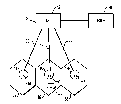
FIG. 1 shows a wireless communication 10 used in accordance with
the present invention. Wireless communication system 10 comprises a mobile
switching center (MSC) 12 and base stations 14, 16, 18. Each of the base
station s14,
16, 18 are connected via T1 lines 22, 24, 26 to MSC 12, which is connected to
a
public switching telephone network (PSTN) 28. Base stations 14, 16, 18 provide
wireless communication services to mobile-telephones within geographic
coverage
areas referred to as cells 34, 36, 38. Associated with each of the base
stations 14, 16,
18 are sets of communication channels for communicating voice and/or data
messages
to and from mobile-telephones within the geographic coverage areas, wherein
the
communication channels have
CA 02261431 1999-02-11
4
associated frequencies. MSC 12 is operable to connect mobile-telephones to
PSTN 28 via base
stations 14, 16, 18, and to manage the resources of base stations 14, 16, 18
including assigning and
unassigning the communication channels belonging to base stations 14, 16, 18.
In order to assign and
unassign communication channels, MSC 12 should have a priori knowledge or be
operable to
determine whether a communication channel is currently assigned to or used by
one or more mobile-
telephones. Alternately, base stations 14, 16, 18 should be operable to manage
its own resources.
Each of the base stations 14, 16, 18 are equipped with cellular radio and/or
Personal
Communication System (PCS) transceivers 40, 42, 44 having performance
monitoring radios,
amplifiers and linearizers, all of which are well-known in the art. The
performance monitoring radios
being operable to receive and demodulate signals and to measure signal
strength on a per
communication channel basis; the amplifiers being operable to amplify the
desired signals; and the
linearizers being operable to linearize the amplifiers. The performance
monitoring radios will have
channel bandwidths corresponding to the standard in use, i.e., 30 kHz for IS-
136 or 1.25 MHz for
IS-95. The performance monitoring radios are utilized by the present invention
to measure the signal
level of the intermodulation products for purposes of tracking the
characteristics and enhancing the
linearization of the amplifiers, as will be described herein.
When signals are to be transmitted by one of the base stations 14, 16, 18, the
signals
are first amplified by the cellular radio/PCS transceivers 40, 42, 44.
Amplification of the signals may
create intermodulation products that will impair transmission or exceed some
acceptable threshold or
standard. Whether or not such intermodulation products are present depend on
the frequencies of the
signals. If these intermodulation products are present, the level of the
intermodulation products are
reduced using the linearizers and performance monitoring radios. Specifically,
the present invention
utilizes the performance monitoring radios to measure the levels of the
intermodulation products
falling on unused communication channels, and the linearizers to adaptively
reduce the level of the
measured intermodulation products.
The performance monitoring radios are used to measure the levels of the
intermodulation products falling on unused communication channels (i.e.,
communication channels
over which none of the amplified signals will be transmitted). Since the
communication channels
over which the signals are being transmitted are known, then the frequencies
associated with such
communication channels are also known. Based on these known frequencies, it is
possible to
calculate the frequencies at which the intermodulation products will fall or
be created, as is well-
known in the art. For example, for two signals: one at F, and the other at Fz,
a third-order non-
linearity will produce intermodulation products at 2F,-FZ and 2Fz-F~. For
three signals: one at F1, one
at F2, and the other one at F3, the intermodulation products will fall at
F1+FZ-F3, F~+F3-FZ, etc.
CA 02261431 1999-02-11
Therefore, given the knowledge of the frequencies of the signals and whether a
communication
channel is currently assigned or used, as mentioned earlier, it is possible to
determine 1 ) the
frequencies at which the intermodulation products will fall, and 2) whether
those frequencies fall on
unused communications channels where the level of the intermodulation products
can be measured
directly. Such information allows the performance monitoring radios to be
tuned to unused
communication channels where the intermodulation products are present and
measure the
corresponding signal levels. Adaptive means can then be used to adjust the
linearizer to reduce the
level of the intermodulation products falling on the unused communication
channels.
Note that the intermodulation products falling on used communication channels
are
not being measured and used for adaptively adjusting the linearizer. The
reason being because other
signals are also present on those communication channels (e.g., voice and/or
data traffic being
transmitted between mobile-telephones and base stations). Thus, the signal
levels of the
intermodulation products falling on used communication channels cannot be
measured directly by the
performance monitoring radios. By contrast, the intermodulation products
falling on the unused
communication channels can be measured directly by the performance monitoring
radios because
only the intermodulation products should be present on those communication
channels or frequencies.
FIG. 2 illustrates a schematic diagram of one possible cellular radio/PCS
transceiver
60 having an amplifier linearization device 62 used in accordance with the
present invention. As
shown in FIG. 2, the amplifier linearization device 62 comprises an amplifier
64, a performance
monitoring radio 66 and a linearizer, wherein the linearizer includes
directional couplers 70, 74, 84,
gain and phase adjusters 72, 78, delays 75, 81, cancellation circuits 76, 82,
correction amplifier 80
and controller 86. In this example, controller 86 receives information (from a
base station or a
mobile-switching center) indicating which communication channels are used or
unused. Based on
this information and the frequencies of the signals, the controller 86
instructs the performance
monitoring radio 66 on which unused communication channels to measure signal
levels for the
intermodulation products created by the signals.
The performance monitoring radio 66 will measure the signal levels of such
intermodulation products in the unused communication channels and relay these
measurements to the
controller 86. The controller 86 will use the measurements from the
performance monitoring radio 66
(and/or the output signal from the cancellation circuit 76) to adaptively
control the gain and phase
adjusters 72 and/or 78 to reduce the level of the intermodulation products in
the output of the feed-
forward amplifier 62. Specifically, the gain and phase adjusters 72 and/or 78
are adjusted to modify
the amplitude and phase of signals entering them such that the signal level of
the intermodulation
products are reduced at the output of the amplifier linearization device 62.
CA 02261431 1999-02-11
6
Note that when certain types of linearizers are adjusted, gain is affected as
well as
linearity. This is undesirable since the goal is generally to reduce the
levels of the intermodulation
product levels without affecting the signal levels of the signals. If only the
intermodulation product
levels are measured, an adaptive system might result in the linearizer simply
reducing the gain and
hence output signal level of the system. For this reason, it is desirable to
hold the output power of the
system constant while adjusting the linearizer. This can be done by measuring
the signal level of a
signal with the performance monitoring radio, and adjusting the output
accordingly. Measurements
of the signal power, intermodulation power, and their ratio will yield enough
information to correctly
adjust the linearizer.
If, for whatever reason, a performance monitoring radio is not available, a
simple
radio could be added to the linearized amplifier system to perform the
function of a performance
monitoring radio. This would of course add to the cost, but at least the
difficulties associated with
pilot tones would be avoided.
Although the present invention has been described in considerable detail with
reference to certain embodiments, other versions are possible. Therefore, the
spirit and scope of the
present invention should not be limited to the description of the embodiments
contained herein.