Language selection

Search

Patent 2261450 Summary

Third-party information liability

Some of the information on this Web page has been provided by external sources. The Government of Canada is not responsible for the accuracy, reliability or currency of the information supplied by external sources. Users wishing to rely upon this information should consult directly with the source of the information. Content provided by external sources is not subject to official languages, privacy and accessibility requirements.

Claims and Abstract availability

Any discrepancies in the text and image of the Claims and Abstract are due to differing posting times. Text of the Claims and Abstract are posted:

  • At the time the application is open to public inspection;
  • At the time of issue of the patent (grant).
(12) Patent Application: (11) CA 2261450
(54) English Title: CUTTING ARRANGEMENT FOR A MATERIAL WEB
(54) French Title: DISPOSITIF DE COUPE D'UN MATERIAU EN CONTINU
Status: Deemed Abandoned and Beyond the Period of Reinstatement - Pending Response to Notice of Disregarded Communication
Bibliographic Data
(51) International Patent Classification (IPC):
  • G03D 15/04 (2006.01)
  • B26D 1/18 (2006.01)
  • B26D 1/20 (2006.01)
  • B26D 5/00 (2006.01)
  • B26D 7/26 (2006.01)
  • B41F 13/60 (2006.01)
  • B41J 11/70 (2006.01)
  • G03B 27/58 (2006.01)
(72) Inventors :
  • HELLER, MARTIN (Switzerland)
(73) Owners :
  • IMIP LLC
(71) Applicants :
  • IMIP LLC (United States of America)
(74) Agent: SMART & BIGGAR LP
(74) Associate agent:
(45) Issued:
(22) Filed Date: 1999-02-10
(41) Open to Public Inspection: 1999-08-11
Examination requested: 2004-01-13
Availability of licence: N/A
Dedicated to the Public: N/A
(25) Language of filing: English

Patent Cooperation Treaty (PCT): No

(30) Application Priority Data:
Application No. Country/Territory Date
98 102 363.3 (European Patent Office (EPO)) 1998-02-11

Abstracts

English Abstract


A cutting arrangement for a material web, especially photographic copy
material in
a photographic copier includes a knife roller (5) and a drive (3, 4, 6 to 9)
for
reciprocating the knife roller (5) between two turnaround positions (S1, S4)
transverse to the material web (M) to be cut, to thereby carry out one cut
respectively. At least two starting positions (S1, S2 or S3, S4) are provided
for each
of the two cutting directions which are associated with different widths of
the
material web (M). The drive (3, 4, 6 to 9) commences the cutting movement of
the
knife roller (5) respectively at that starting position (S1, S2 or S3, S4)
associated for
one cutting direction with the respective material web width and moves the
knife
roller (5) after completion of the cut to the respectively closest turnaround
position
(S1, S4) and from thereback to the starting position (S4, S3 or S2, S1)
associated for
the other cutting direction with the respective material web width, provided
that the
latter starting position (S4, S3 or S2, S1) does not coincide with a
turnaround position
(S1, S4). The arrangement of different starting positions for material webs of
different width makes time savings of up to over 50% possible.


Claims

Note: Claims are shown in the official language in which they were submitted.

-6-
CLAIMS
1. Cutting arrangement for a material web, especially photographic copy
material
in a photographic copier, comprising a knife roller for cutting the material
web and
a drive, for reciprocating the knife roller between at least two turn back or
retracing
positions transverse to the material web to respectively carry out one cut,
whereby
at least two starting positions are provided for each of at least two cutting
directions
and coordinated with different widths of the material web, the drive starting
the
cutting movement of the knife roller respectively at the starting position
associated
with the respective material web width and for one cutting direction and
moving the
knife roller after completion of the cut to the respectively closer turnaround
position
and from there back to the starting position associated with the other cutting
direction for the respective material web width, provided that the latter
starting
position does not coincide with a turn back or retracing position.
2. Arrangement according to claim 1, wherein two outer starting positions are
provided which coincide with the turn back or retracing positions and two
inner
starting positions are provided which are positioned therebetween.
3. Arrangement according to claim 2, further comprising an inner and an outer
hold-down member for clamping the material web to be cut which hold-down
members are operable by the knife roller, whereby the inner hold down member
is
positioned between the inner starting positions and the outer hold down member
functions in the regions between respectively one of the inner starting
positions and
the respectively closest outer starting position.
4. Arrangement according to claim 1, further comprising a stationary knife bar
for
cooperating with the knife roller, the knife bar extending essentially between
the at
least two turn back or retracing positions of the knife roller.

Description

Note: Descriptions are shown in the official language in which they were submitted.


CA 02261450 1999-02-10
CUTTING ARRANGEMENT FOR A MATERIAL WEB
Field Of The Invention
The invention relates to a cutting arrangement for a material web. In
particular, the
invention relates to a cutting arrangement for photographic copy material in a
photographic copier apparatus.
Background Of The Invention
In photographic copiers, especially so-called mini labs, cutting arrangements
including a knife roller and a drive for reciprocating the knife roller
transverse to the
material web are often used especially for larger paper widths, since they
have
various advantages compared to other cutting arrangements. However, if copy
paper webs of different widths are processed in the copier apparatus, the
cutting
time for more narrow paper webs is the same as for the widest paper web for
which the cutting arrangement or the copier apparatus is constructed. This is
perceived disadvantageous in time sensitive application s.
Summary Of The Invention
A cutting arrangement of the art is now to be improved with the present
invention
such that it provides shorter cutting times for more narrow material webs than
for
wider material webs.
The solution of the problem underlying the invention results from the features
of the
cutting arrangement in accordance with the invention whereby at least two
starting
positions are provided for each of the two cutting directions and coordinated
with
different widths of the material web and the cutting movement of the knife
roller is
started respectively, the starting position associated with the respective
material
web width and for one cutting direction.
Further, advantageous and especially practical embodiments of the cutting
arrangement in accordance with the invention are described below.

CA 02261450 1999-02-10
-2-
Detailed Description Of The Drawings
The invention will be further described in the following with reference to the
drawing. It show:
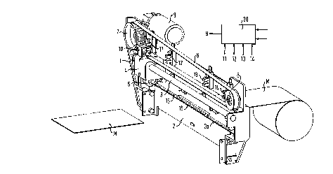
FIG. 1 a complete view of a typical embodim ent of the cutting arrangem ent
in accordance with the invention in/perspective illustration;
FIG. 2 a front elevation of the cutting arrangement of FIG. 1;
FIG. 3 a.sketch explaining the function of the cutting arrangement; and
FIGS. 4 and 5 two schematic detailed views for illustration of the function.
Description Of The Preferred Embodiments
The illustrated cutting arrangement includes a frame 1 to which all components
are
mounted. The frame and, therefore, the whole cutting arrangem ent is in
practical
use installed transverse to the path of a material web to be cut. A stationary
beam
2 is provided in the lower region of the frame on which upper edge a knife bar
2a
is positioned. Furthermore, a slide track 3 is mounted in the frame 1 on which
a
knife sled 4 is moveably supported. A knife roller 5 is rotatably mounted in
the knife
sled 4, which roller cooperates with the stationary knife bar 2a. The knife
sled 4 is
affixed to a toothed belt 6 which is guided around two rollers 7 and 8. The
roller 7
shown on the left side in the drawings is driven by a drive motor 9 mounted to
the
frame 1. The knife roller 5 is thereby reciprocatable along the knife bar 2a
by way
of the motor. The illustrated cutting arrangement so far essentially
corresponds to
arrangements in the art.
Four photo detectors 11, 12, 13 and 14 are positioned on the frame 1 along the
path of the knife sled 4, which photo detectors cooperate with a flag 10
positioned
on the knife sled 4. The four photo detectors 11-14 cooperate with an
electronic
control symbolically illustrated by the box 20, which controls the drive motor
9 and,
thereby, the movement of the knife roller 5 along the knife bar 2a. The four
photo

CA 02261450 1999-02-10
-3-
detectors define four start positions S,-S4 (FIG. 3) for the knife roller 5,
whereby the
two outer start positions S, and S4 are at the same time also the turnaround
or turn
back positions for the reciprocating movemen t of the knife roller 5. The
controller
20 receives from a not illustrated superior control the information with
respect to
the width of the material web to be cut as well as a start signal for the
triggering of
the cutting process. Of course, the controller 20 and the superior control can
also
be combined into one control arrangement which, when used in a photographic
copier, can also be implemented by the control included therein for the other
components thereof.
According to the underlying principle of the invention, the cutting
arrangement is
provided with different start positions for the knife roller for the cutting
of material
webs of different width. In the illustrated embodiment, only two material web
widths
are differentiated, typically about _< 4" and > than 4". For more narrow
material
webs (<_4") the two inner start positions S2 and S3 are relevant, for wider
material
webs (>4") the two outer start positions S, and S4 apply, which, at the same
time,
define the turnaround or retracing points of the movement. The start positions
are
furthermore respectively assigned to one cutting direction (direction of
movement of
the knife roller 5). For the cutting direction from left to right in the
drawing, the start
positions S, and S2 apply for wider or more narrow material webs respectively,
for
the reverse cutting direction from right to left) the starting positions S4
and S3 apply
for wider or smaller material webs.
The functioning of the cutting arrangem ent and the sequence of the movem ents
of
the knife roller are best apparent from FIG. 3.
It is assumed that initially a more narrow material web (~4") is to be cut.
The knife
sled 4 and, thereby, the knife roller 5 therefore are located at starting
position S2.
As soon as the length of the material web M to be cut is advanced across the
knife
bar 2) the cutting cycle is initiated by a not illustrated superior control.
The knife
roller 5 is thereby moved to the right initially to the starting position S3,
whereby the
material web is cut, and from there further to the turnaround or turn back
position

CA 02261450 1999-02-10
-4-
S4 and, finally, back to the starting position S3) where it remains until the
next
cutting cycle. In the next cutting cycle, the knife roller 5 starting from the
starting
position S3 is initially moved to the starting position S2 and from there
further to the
turn back position S, and, finally, back to the starting position S2, where it
remains
until the start of the next cutting cycle. The sequence of movem ent for these
two
cutting cycles is illustrated in FIG. 3 by line 30.
Of course) it is also possible with more narrow material webs to reciprocate
the
knife roller 5 only between the two inner starting positions S2 and S3. The
further
movement after the cutting to the respectively closest turnaround or retracing
position and back to the inner starting position, however, provides the
advantage
that the knife bar is not unevenly worn.
With wider material webs (>4"), the knife roller is moved back and forth in
conventional manner between the two turn back positions S, and S4 as starting
positions. The sequence of movements for these two cutting cycles is
illustrated in
FIG. 3 by line 40.
It is required for a clean cut that the material web M is pressed against the
knife
bar 2a during the cutting process. According to the invention, two hold-down
members 15 and 16 are provided therefor which are operated by the knife roller
5
(FIGS. 4 and 5). The first, inner hold-down member 15 is essentially
positioned
between the two inner starting positions S2 and S3) the second, outer hold-
down
member 16 is located in the two regions between respectively an inner starting
position S2 or S3 and the respectively closest turnaround or retracing
position S, or
S4, i.e., to both sides of the inner hold-down member 15. The two hold-down
members 15 and 16 consist essentially of rods parallel to the knife bar 2a,
which,
in the at rest position, are held by not illustrated springs at a small
distance above
the knife bar 2a. The material web M to be cut is guided between the knife bar
2a
and the two hold-down members 15 and 16.
The knife roller 5 is provided with a coaxial rubber roller 17 of somewhat
smaller

CA 02261450 1999-02-10
-5-
diameter for actuating the two hold-down members 15 and 16. In the two
turnaround or turn back positions S, and S4, the rubber roller 17 is not in
engagement with the outer hold-down member 16 (and) of course, not with the
inner hold-down member 15), the two hold-down members 15 and 16 therefore are
in their at rest position spaced apart from the knife bar 2a, so that a
material web
advance is possible over the total available width of the cutting arrangement.
As
soon as the knife roller 5 is moved inward, the rubber roller 17 engages with
the
outer hold-down member 16, and pushes the latter downward towards the knife
bar
2a, whereby the material web M is clamped in place. When the knife roller 5 is
moved inward beyond the two inner start positions S2 or S3, the inner hold-
down
member 15 is analogously pressed downward and vice versa. When the knife
roller
is at one of the two inner starting positions S2 and S3) the rubber roller 17
is not
in engagement with the inner hold-down member 15 so that a more narrow
material web can be inserted or advanced.
Time savings of up to 50% are possible with the arrangem ent in accordance
with
the invention providing starting positions for material webs of different
width.

Representative Drawing
A single figure which represents the drawing illustrating the invention.
Administrative Status

2024-08-01:As part of the Next Generation Patents (NGP) transition, the Canadian Patents Database (CPD) now contains a more detailed Event History, which replicates the Event Log of our new back-office solution.

Please note that "Inactive:" events refers to events no longer in use in our new back-office solution.

For a clearer understanding of the status of the application/patent presented on this page, the site Disclaimer , as well as the definitions for Patent , Event History , Maintenance Fee  and Payment History  should be consulted.

Event History

Description Date
Inactive: IPC from MCD 2006-03-12
Time Limit for Reversal Expired 2006-02-10
Application Not Reinstated by Deadline 2006-02-10
Deemed Abandoned - Failure to Respond to Maintenance Fee Notice 2005-02-10
Letter Sent 2004-01-26
Request for Examination Received 2004-01-13
All Requirements for Examination Determined Compliant 2004-01-13
Request for Examination Requirements Determined Compliant 2004-01-13
Letter Sent 2002-10-18
Inactive: Cover page published 1999-08-19
Application Published (Open to Public Inspection) 1999-08-11
Inactive: IPC assigned 1999-03-31
Classification Modified 1999-03-31
Inactive: First IPC assigned 1999-03-31
Inactive: IPC assigned 1999-03-30
Filing Requirements Determined Compliant 1999-03-11
Inactive: Filing certificate - No RFE (English) 1999-03-11
Application Received - Regular National 1999-03-10

Abandonment History

Abandonment Date Reason Reinstatement Date
2005-02-10

Maintenance Fee

The last payment was received on 2003-12-23

Note : If the full payment has not been received on or before the date indicated, a further fee may be required which may be one of the following

  • the reinstatement fee;
  • the late payment fee; or
  • additional fee to reverse deemed expiry.

Please refer to the CIPO Patent Fees web page to see all current fee amounts.

Fee History

Fee Type Anniversary Year Due Date Paid Date
Registration of a document 1999-02-10
Application fee - standard 1999-02-10
MF (application, 2nd anniv.) - standard 02 2001-02-12 2001-01-17
MF (application, 3rd anniv.) - standard 03 2002-02-11 2002-01-15
Registration of a document 2002-09-11
MF (application, 4th anniv.) - standard 04 2003-02-10 2003-01-24
MF (application, 5th anniv.) - standard 05 2004-02-10 2003-12-23
Request for examination - standard 2004-01-13
Owners on Record

Note: Records showing the ownership history in alphabetical order.

Current Owners on Record
IMIP LLC
Past Owners on Record
MARTIN HELLER
Past Owners that do not appear in the "Owners on Record" listing will appear in other documentation within the application.
Documents

To view selected files, please enter reCAPTCHA code :


To view images, click a link in the Document Description column. To download the documents, select one or more checkboxes in the first column and then click the "Download Selected in PDF format (Zip Archive)" or the "Download Selected as Single PDF" button.

List of published and non-published patent-specific documents on the CPD .

If you have any difficulty accessing content, you can call the Client Service Centre at 1-866-997-1936 or send them an e-mail at CIPO Client Service Centre.


Document
Description 
Date
(yyyy-mm-dd) 
Number of pages   Size of Image (KB) 
Representative drawing 1999-08-19 1 13
Cover Page 1999-08-19 1 48
Description 1999-02-10 5 227
Abstract 1999-02-10 1 31
Claims 1999-02-10 1 50
Drawings 1999-02-10 3 60
Courtesy - Certificate of registration (related document(s)) 1999-03-11 1 117
Filing Certificate (English) 1999-03-11 1 165
Reminder of maintenance fee due 2000-10-11 1 110
Reminder - Request for Examination 2003-10-14 1 112
Acknowledgement of Request for Examination 2004-01-26 1 174
Courtesy - Abandonment Letter (Maintenance Fee) 2005-04-07 1 174
Correspondence 2002-10-18 1 16
Correspondence 2002-10-23 1 13
Fees 2003-01-24 1 31
Fees 2003-12-23 1 31
Fees 2002-01-15 1 32
Fees 2001-01-17 1 31