Language selection

Search

Patent 2261555 Summary

Third-party information liability

Some of the information on this Web page has been provided by external sources. The Government of Canada is not responsible for the accuracy, reliability or currency of the information supplied by external sources. Users wishing to rely upon this information should consult directly with the source of the information. Content provided by external sources is not subject to official languages, privacy and accessibility requirements.

Claims and Abstract availability

Any discrepancies in the text and image of the Claims and Abstract are due to differing posting times. Text of the Claims and Abstract are posted:

  • At the time the application is open to public inspection;
  • At the time of issue of the patent (grant).
(12) Patent Application: (11) CA 2261555
(54) English Title: ELECTRONIC APPARATUS HAVING AN ENVIRONMENTALLY SEALED EXTERNAL ENCLOSURE
(54) French Title: APPAREIL ELECTRONIQUE MUNI D'UN BOITIER HERMETIQUE
Status: Deemed Abandoned and Beyond the Period of Reinstatement - Pending Response to Notice of Disregarded Communication
Bibliographic Data
(51) International Patent Classification (IPC):
  • H01L 23/02 (2006.01)
  • H05K 7/20 (2006.01)
(72) Inventors :
  • GATES, WILLIAM GEORGE (United Kingdom)
(73) Owners :
  • LUCENT TECHNOLOGIES INC.
(71) Applicants :
  • LUCENT TECHNOLOGIES INC. (United States of America)
(74) Agent: KIRBY EADES GALE BAKER
(74) Associate agent:
(45) Issued:
(22) Filed Date: 1999-02-10
(41) Open to Public Inspection: 1999-09-24
Examination requested: 1999-02-10
Availability of licence: N/A
Dedicated to the Public: N/A
(25) Language of filing: English

Patent Cooperation Treaty (PCT): No

(30) Application Priority Data:
Application No. Country/Territory Date
98302166.8 (European Patent Office (EPO)) 1998-03-24

Abstracts

English Abstract


Electronic apparatus is disclosed having components
mounted within an environmentally sealed external enclosure.
The enclosure comprises a casting of heat conductive
material and ones of the components are mounted in heat
conductive association with one or more walls of the
enclosure. These one or more walls have external pin fins
projecting therefrom.
Conventional extended surfaces are, in effect, flat
strips extending a significant distance along the surface of
the enclosure. The pin fins of the present invention
improve cooling compared with conventional fins. The
enclosure may be lighter in weight than an enclosure that
has conventional fins.


Claims

Note: Claims are shown in the official language in which they were submitted.

-5-
CLAIMS
1. Electronic apparatus having components
mounted within an environmentally sealed external enclosure
comprising a casting of heat conductive material and ones of
the components being mounted in heat conductive association
with one or more walls of the enclosure, said one or more
walls having external pin fins projecting therefrom.
2. Apparatus as claimed in claim 1, wherein the
enclosure is contained by a vented case, the pin fins
projecting into air passages between the enclosure and the
case.
3. Apparatus as claimed in claim 2, including a
blower to force a flow of air across the pin fins.
4. Apparatus as claimed in claim 3, wherein the
blower is a centrifugal fan arranged between the pin fins on
a wall of the enclosure.

Description

Note: Descriptions are shown in the official language in which they were submitted.


CA 02261555 1999-02-10
- 1 -
ELECTRONIC APPARATUS HAVING AN ENVIRONMENTALLY
SEALED EXTERNAL ENCLOSURE
This invention relates to electronic apparatus
having components mounted within an environmentally sealed
external enclosure.
Much electronic apparatus requires cooling. In many
cases this is effected by blowing air through the enclosure
via vents. In some situations, for example when the
apparatus is to be used outside, the external enclosure must
be environmentally sealed. One example is the base station
equipment for a mobile communications network, where an
enclosure containing a transmitter/receiver, a power
amplifier, a processor and other units, is mounted outside
e.g. on a pole. The environmental seal prevents air from
being blown through the enclosure. Conventionally, the
enclosure may be provided with extended surfaces to increase
its surface area so allowing the enclosure, and thus its
contents, to be cooled by convection.
Against this background there is provided electronic
apparatus having components mounted within an
environmentally sealed external enclosure comprising a
casting of heat conductive material and ones of the
components being mounted in heat conductive association with
one or more walls of the enclosure, said one or more walls
having external pin fins projecting therefrom.
The conventional extended surfaces are, in effect,

CA 02261555 1999-02-10
- 2 -
flat strips extending a significant distance along the
surface of the enclosure. The pin fins of the present
invention improve cooling compared with conventional fins.
The enclosure may be lighter in weight than an enclosure
that has conventional fins.
In a preferred form, the enclosure is contained by a
vented case, the pin fins projecting into air passages
between the enclosure and the case.
A blower may be provided to force a flow of air
across the pin fins. Forced air flow across the pin fins
provides a great improvement in cooling.
Most preferably the blower is a centrifugal fan
arranged between the pin fins on a wall of the enclosure.
The centrifugal fan can be placed amongst the pins to draw
or blow air in all directions across the pin fins. In
contrast, for conventional fins the air flow has to be in
one direction so a fan has to be placed beyond the end of
the fins. and the fins are best placed so that laminar flow
does not occur between the fins. Using pin fins, the fan
can be placed without extending the product line to
accommodate it. Further, laminar flow cannot be established
between the pin fins so they can be more closely spaced.
One embodiment of the invention will now be
described, by way of example, with reference to the
accompanying drawings, in which:
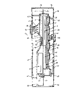
Figure 1 is a cross section through base station
equipment for a mobile telecommunications network and

CA 02261555 1999-02-10
- 3 -
embodying the invention; and
Figure 2 is a top plan of the equipment of Figure 1
with part of the top of its outer case broken away.
Referring to the drawings, base station equipment
for a mobile telecommunications network has a thermally
conductive external enclosure 2 cast, for example from light
metal in two parts 2a and 2b environmentally sealed around a
joint between two flanges 2c. The enclosure contains two
transmitter/receiver units 4, two power amplifiers 6, two
duplexers 8 and a processor board 10. The
transmitter/receiver units 4 and power amplifiers 6 are
shielded against radio frequency emissions by aluminium
cases 12 and 14. The two power amplifiers 6 are mounted
side by side on a wall 16 of the container so only one is
visible in Figure 1. Similarly the two duplexers 8 are
mounted side by side on the ::all 16. The power amplifiers
and duplexers are thus in thermally conductive contact with
the walls 16. A circuit board 20 is mounted in contact with
a wall 22 of the case 14 so that components on the board are
in conductive association t~~ith the wall 16, that is to say
heat generated by a component can be conducted to the wall
16 via the circuit board 20 and the wall 22 of the case 14.
The processor board 10 is mounted directly on a wall
24 opposite the wall 16, again in thermally conductive
contact. Components on the processor board 10 are thus also
in thermally conductive association with the wall 24.
The transmitter/receiver units 4 are mounted on

CA 02261555 1999-02-10
- 4 -
pillars 26 over the processor board 10.
The external enclosure 2 is contained by a
ventilated case 28 having a vents 30 in its bottom 32 and
vents 34 in its top 36.
The walls 16 and 24 have pin fins 40 which project
into air passages 42 between the enclosure 2 and the case
28. The pin fins ensure that air flow over them is
turbulent so providing a significant improvement over
r
conventional flat extended strip fins where spacing has to
be carefully chosen so that laminar flow does not build up
across the space between the them.
Components in the enclosure are thus cooled by
thermal conduction to and through the walls 16 and 24 of the
enclosure 2 and by natural convection over the extended
strip fins 40.
Cooling is assisted by blowers in the form of
centrifugal fans 44 each having an impeller 4G driven by an
electric motor 48 (only one motor is shown). The fans are
mounted on respective walls 16 and 24 surrounded by pin
fins. The fans draw air in through apertures 50 and blow it
in all directions through the pin fins, that not being
possible with conventional strip fins.

Representative Drawing
A single figure which represents the drawing illustrating the invention.
Administrative Status

2024-08-01:As part of the Next Generation Patents (NGP) transition, the Canadian Patents Database (CPD) now contains a more detailed Event History, which replicates the Event Log of our new back-office solution.

Please note that "Inactive:" events refers to events no longer in use in our new back-office solution.

For a clearer understanding of the status of the application/patent presented on this page, the site Disclaimer , as well as the definitions for Patent , Event History , Maintenance Fee  and Payment History  should be consulted.

Event History

Description Date
Inactive: IPC from MCD 2006-03-12
Application Not Reinstated by Deadline 2004-02-10
Time Limit for Reversal Expired 2004-02-10
Deemed Abandoned - Conditions for Grant Determined Not Compliant 2003-04-16
Deemed Abandoned - Failure to Respond to Maintenance Fee Notice 2003-02-10
Notice of Allowance is Issued 2002-10-16
Letter Sent 2002-10-16
Notice of Allowance is Issued 2002-10-16
Inactive: Approved for allowance (AFA) 2002-10-01
Amendment Received - Voluntary Amendment 2002-07-08
Inactive: S.30(2) Rules - Examiner requisition 2002-04-15
Application Published (Open to Public Inspection) 1999-09-24
Inactive: Cover page published 1999-09-23
Classification Modified 1999-04-01
Inactive: First IPC assigned 1999-04-01
Inactive: IPC assigned 1999-04-01
Inactive: Single transfer 1999-03-31
Inactive: Courtesy letter - Evidence 1999-03-16
Inactive: Filing certificate - RFE (English) 1999-03-12
Filing Requirements Determined Compliant 1999-03-12
Application Received - Regular National 1999-03-12
Request for Examination Requirements Determined Compliant 1999-02-10
All Requirements for Examination Determined Compliant 1999-02-10

Abandonment History

Abandonment Date Reason Reinstatement Date
2003-04-16
2003-02-10

Maintenance Fee

The last payment was received on 2001-12-28

Note : If the full payment has not been received on or before the date indicated, a further fee may be required which may be one of the following

  • the reinstatement fee;
  • the late payment fee; or
  • additional fee to reverse deemed expiry.

Please refer to the CIPO Patent Fees web page to see all current fee amounts.

Fee History

Fee Type Anniversary Year Due Date Paid Date
Request for examination - standard 1999-02-10
Registration of a document 1999-02-10
Application fee - standard 1999-02-10
MF (application, 2nd anniv.) - standard 02 2001-02-12 2000-12-20
MF (application, 3rd anniv.) - standard 03 2002-02-11 2001-12-28
Owners on Record

Note: Records showing the ownership history in alphabetical order.

Current Owners on Record
LUCENT TECHNOLOGIES INC.
Past Owners on Record
WILLIAM GEORGE GATES
Past Owners that do not appear in the "Owners on Record" listing will appear in other documentation within the application.
Documents

To view selected files, please enter reCAPTCHA code :


To view images, click a link in the Document Description column. To download the documents, select one or more checkboxes in the first column and then click the "Download Selected in PDF format (Zip Archive)" or the "Download Selected as Single PDF" button.

List of published and non-published patent-specific documents on the CPD .

If you have any difficulty accessing content, you can call the Client Service Centre at 1-866-997-1936 or send them an e-mail at CIPO Client Service Centre.


Document
Description 
Date
(yyyy-mm-dd) 
Number of pages   Size of Image (KB) 
Representative drawing 1999-09-09 1 12
Cover Page 1999-09-09 1 38
Description 2002-07-08 5 165
Abstract 2002-07-08 1 22
Claims 2002-07-08 1 23
Abstract 1999-02-10 1 22
Description 1999-02-10 4 138
Claims 1999-02-10 1 20
Drawings 1999-02-10 2 45
Filing Certificate (English) 1999-03-12 1 165
Courtesy - Certificate of registration (related document(s)) 1999-05-05 1 116
Reminder of maintenance fee due 2000-10-11 1 110
Commissioner's Notice - Application Found Allowable 2002-10-16 1 163
Courtesy - Abandonment Letter (Maintenance Fee) 2003-03-10 1 178
Courtesy - Abandonment Letter (NOA) 2003-06-25 1 165
Correspondence 1999-03-16 1 32