Note: Descriptions are shown in the official language in which they were submitted.
CA 02261661 1999-O1-27
WO 98/04643 . PCT/US97/12490 - -
1
METHOD AND APPARATUS FOR CONTINUOUS
PREPARATION OF CORRUGATING ADHESIVE
Technical Field
This invention relates to corrugating adhesives and more
particularly to a method and apparatus for the continuous
preparation of corrugating adhesive to minimize waste, improve
properties and to reduce costs.
Background of the Invention
Adhesives used in manufacturing corrugated board are
usually comprised of starch, a boron containing compound,
caustic or another basic agent, and optionally a water
resistance additive, where water resistance is needed, all
provided in a water base. The major component of the adhesive
is the starch which is gelatinized in the corrugating process
after it penetrates the paper fiber. The other components are
agents which modify the basic properties of the starch. For
example, caustic usually in the form of sodium hydroxide,
modifies the gelation temperature of the starch. Boron
containing compounds are used to adjust or modify the adhesive
CA 02261661 1999-O1-27
WO 98/04643 PCT/US97/12490- -
2
tackiness, while also acting as buffering agents and to
maintain the viscosity. Water resistance additives, which are
optionally used, are typically derived from urea-formaldehyde,
ketone formaldehyde or melamine-formaldehyde. Further, it is
possible to use other poly-hydroxide compounds other than or in
addition to starch in the adhesive compositions. For example,
polyvinyl alcohol will work with the boron containing compounds
in a manner similar to that of raw starch.
Starch based adhesives are typically made in a batch
process by first preparing two separate portions, a cooked
starch portion referred to as a "carrier" starch, and an
uncooked portion referred to as "raw" starch. This is
necessary to avoid creating an adhesive too viscous to be
handled easily.
Typically, the carrier starch is prepared in a first tank
by adding fresh water to starch, which may be either in raw or
modified form. The mixture is agitated to form a starch
slurry. Caustic is then admixed with the starch slurry and
heated to initiate gelation and thereby produce the carrier
starch paste portion.
In a second tank, water and starch, typically an
unmodified raw starch, are agitated to form a raw starch slurry
to which the boron containing compound, typically boric acid or
borax is added. After the raw starch portion has been
thoroughly mixed, the carrier starch portion is added to it and
CA 02261661 1999-O1-27
WO 98/04643
PCT/US97/12490- -
3
both are thoroughly mixed together to yield the corrugating
adhesive, typically having a solids content of about 17 to 350
by weight and a viscosity in the range of about 150 to 650
centipoises.
' S The admixed starch adhesive is typically located in a tank
of about 565 to 7,570 liters capacity, with the mixture
circulated to a corrugator on demand.
One problem with the prior batch systems is that adhesive
preparation must be scheduled to satisfy demand as to timing,
amount, specific formulation, viscosity, gel temperature and
storage temperature. Generally, large storage tanks are
necessary with their number and capacity depending on the
variety of formulations and the number of use points within a
facility.
After the adhesive has been formulated, any of a number of
variables such as the degree of agitation in the tanks, the
amount of circulation in the pipes, maintenance of particular
temperatures, the continuing action of the basic agent (sodium
hydroxide) on the starch in the paste and moisture loss, etc.,
may cause significant variations in the adhesive viscosity.
Further, the costs for batch systems are high due to the need
to have a number of storage tanks and specialized equipment for
handling the viscous adhesive, while at the same time
controlling the various parameters to avoid detrimental
viscosity changes.
CA 02261661 2004-09-15
4
For example, once the admixture is created, the adhesive
begins to age and it is subject to thickening or thinning a:nd
viscosity breakdown, which can detrimentally effect the
properties of the ~~orrugated product. While various methods
have been attempted to control temperature so as to reduce the
deterioration in properties with time, it is typical for there
to be a significant amount of unused corrugating adhesive,
which, once a run :is complete, must be disposed of or worked
into a new batch o.f adhesive. Because of the time required to
use up a batch of adhesive, the corrugated product quality may
vary due to the decrease in the beneficial properties of the
corrugating adhesive with time.
Summary of the Invention
It is an object of an aspect of the present invention to
provide a method for preparing a corrugating adhesive on an a~>
needed basis so as to minimize the amount of holdup within the
system to reduce wastage.
It is a further object of an aspect of the present
invention to provide a method for continuously preparing
corrugating adhesives so as to maintain the optimum properties.
of the adhesive during the course of a corrugating run.
It is another object of an aspect of the invention to
provide a method fc>r changing the adhesive formulation by
drawing from individual stored components virtually immediately
to minimize downtime between
CA 02261661 1999-O1-27
WO 98/04643 PCT/US97/12490 - - -
corrugating runs.
These and other objects of the present invention are
achieved by a continuous process for producing a starch based
corrugating adhesive. The adhesive is formulated as needed in
5 a rate corresponding substantially to the rate of demand of the
corrugator. Viscosity and. temperature are continually
monitored and controlled just prior to placement on the sheet
and there is minimized holdup of any adhesive to eliminate the
problems of aging and other degrading factors.
In the invention, a carrier portion of a~starch slurry is
prepared on a continuous basis by its admixture with a basic
agent (sodium hydraxidey, to produce a low volume smooth
adhesive paste. This is then continually mixed with other
adhesive ingredients, which are all stored separately at room
temperature in liquid or paste form at concentrations which
allow for instantaneous mixing of the various combinations of
ingredients, immediately prior to transfer to the corrugator.
The only adhesive holdup occurs within a small vessel including
mixing and testing chambers, from which the adhesive is
delivered to the corrugator, the vessel including means for
monitoring the viscosity and for adjusting the quantity of
starch slurry mixed with the basic agent so as to obtain the
optimum viscosity of the adhesive immediately prior to delivery
to the corrugator.
The present invention provides a method for continuously
CA 02261661 1999-O1-27
WO 98/04643 PCT/US97/12490 - - -
6
producing corrugating adhesive comprising providing a rate
controlled first stream of a basic agent, providing a portion
of a rate controlled second stream of raw slurry, admixing the
two flowing streams, feeding the admixture to a first chamber,
optionally adding a third stream of raw slurry to the first
chamber in a rate corresponding to the flow rate of the basic
agent, optionally adding water in a corresponding rate to the
first mixing chamber and adding a boron containing compound in
a similar corresponding rate to the first mixing chamber,
mixing the contents of the first chamber together to form an
adhesive, providing a second chamber, adjacent to the first
chamber, locating viscosity sensor means in the second chamber,
providing means for controlling the rates of addition of the
rate controlled streams to produce a mixture of properly
metered ingredients to the first chamber in a rate
corresponding substantially to the rate of use of the adhesive,
passing the adhesive through to the second chamber, measuring
the viscosity and adjusting the rate of flow of the portion of
the second stream of raw starch to control the viscosity for
providing a controlled stream of continuously produced
corrugating adhesive to a corrugator.
By controlling the flow of each corrugating adhesive
ingredient, with the amount of materials proportioned to the
flow of the basic agent, very small portions of corrugating
adhesive are produced, and very nearly immediately mixed and
CA 02261661 2005-06-29
7
transferred to a chamber containing a viscosity sensing
apparatus. A control signal generated by the apparatus is
then used to adjust the flow of the second stream of raw
starch in the admixture so as to achieve the proper
viscosity of adhesive before it is transported to a
corrugator pan. The total feed rate of the ingredients
closely approximates the adhesive take up at the corrugator
so that very little time passes between the mixing of the
ingredients and their placement on the corrugated paper
such that properties do not have an opportunity to degrade.
Consequently, fresh adhesive is continuously available
throughout a corrugator run. Further, changes in processing
parameters, such as the need to include a water resistance
additive or to adjust the adhesive tackiness or other
properties can be made virtually immediately, so as, for
example, to simplify change over from one corrugated
product to another. Consequently, waste adhesive is
substantially eliminated while properties and yields are
optimized.
Accordingly, in one aspect there is provided an
apparatus for producing a corrugating adhesive on a
continuous basis comprising:
a mixing vessel having a mixing chamber and a testing
chamber;
a baffle separating the mixing chamber from the
testing chamber;
a first feed means for controlled continuous feeding
of a basic agent to the mixing chamber;
a second feed means for controlled feeding of a raw
starch slurry to the mixing chamber;
a means connected to the first and second feed means
for admixing the basic agent and a variably controlled
portion of raw starch slurry prior to their entering the
mixing chamber;
CA 02261661 2005-06-29
7a
a diverter means for diverting some or all of the
variably controlled portion of raw starch slurry to the
admixer means, any undiverted portion added to the mixing
chamber;
a third feed means for controlled optional feeding of
additional raw starch slurry to the mixing chamber;
a fourth feed means for controlled optional feeding of
water to the mixing chamber; and
a fifth feed means for controlled optional feeding of
a boron containing compound to the mixing chamber, each of
the first, second, third, fourth and fifth feed means
providing a predetermined proportion of an ingredient of
the corrugating adhesive;
an agitator means located in the mixing chamber for
thoroughly mixing the ingredients in the mixing chamber
together, to form the corrugating adhesive; and
a viscosity sensing means, located in the testing
chamber, for sensing the viscosity of the mixed ingredients
and for generating a control signal for controlling the
diverter means to adjust the viscosity by altering the
proportion of admixed ingredients.
According to another aspect there is provided a method
for producing a corrugating adhesive at a continuous rate
substantially equivalent to a rate of adhesive use in a
corrugating apparatus, comprising:
providing a first rate controlled stream of basic
agent;
providing a second rate controlled stream of a raw
starch slurry;
admixing the first and a variable portion of the
second rate controlled streams to form a third rate
controlled stream and feeding the third rate controlled
stream to a first chamber, the remaining portion of the
second rate controlled stream added to the first chamber;
CA 02261661 2005-06-29
7b
simultaneously adding a boron containing compound
stream to the first chamber, and simultaneously optionally
adding an additional raw starch slurry stream and a water
stream to the first chamber, each added to the first
chamber in a rate proportional to the flow rate of either
the first rate controlled stream or the second rate
controlled stream;
mixing the streams together in the first chamber as
they pass therethrough to form an adhesive;
providing a second chamber, adjacent to the first
chamber;
locating a viscosity sensor in the second chamber;
passing the adhesive at a rate corresponding to the
total rate of addition of the streams added to the first
chamber to the second chamber;
sensing the viscosity of the adhesive using the
viscosity sensor and generating a control signal therefrom;
adjusting the rate of the variable portion of the
second rate controlled stream in response to the control
signal to adjust the adhesive viscosity; and,
supplying the adhesive to the corrugating apparatus.
Brief Description gs
of the Drawin
Embo diments of the presentinve ntion will now be
described more fully with reference to the accompanying
drawings in which:
Fig. 1 is a schematic view of corrugating process
a
Fig. 2 is an enlarged view of corrugating pan.
a
Fig. 3 is an illustration of system for continuously
a
preparing a corrugating adhesive.
Fig. 4 is an illustrating view
of
a
piston
apparatus
for
CA 02261661 1999-O1-27
WO 98/04643 _ PCT/US97/12490 - -
8 _
feeding the adhesive ingredients.
Fig. 5 is a cross-sectional view of an experimental
testing apparatus.
Fig. 6 is an alternative mixing vessel usable with the
present invention.
Detailed Description of the Invention
Referring to Fig. 1, a corrugating production line is
illustrated. In this process, an adhesive is applied to the
tips of the flutes of a corrugated medium.
A corrugator 1 has a first station 2 where a kraft paper
medium 3 is passed between a pair of meshed rolls 4 and 5 which
bend the medium to form corrugations 6. An adhesive paste 7 is
applied to tips 8 of the corrugations on one side of the sheet
which is then joined to a first liner 9, in the presence of
heat and pressure. The first liner 9 passes by a preheater 10
and then over a roll 11 for joining the liner to the corrugated
medium. The bond at this point must be of sufficient strength
and flexibility to withstand the rigorous handling to which the
sheet is subjected. This bond is known as the "green bond".
At a second station 12, adhesive 13 is applied to tips 14
of the corrugations on the reverse side of the sheet which is
then joined to a second liner 15, which passes over a preheater
16. The assembled board 17 is then passed between two parallel
flat horizontal lightly pressing surfaces 18 and 19, one of
CA 02261661 1999-O1-27
WO 98/04643 _ PCT/US97/12490- -
9
which is heated with steam to completely gel the adhesive such
that when the board emerges from the corrugator, it is a
. finished flat board 20, which is cut by a knife 21 and stacked
as finished blanks 22.
The product resulting from the first station 2, having the
corrugating medium on one side and a flat liner on the other
side, is termed a "single faced portion". The single faced
portion may be used as is or the portion may proceed to the
second station 12, where adhesive is applied to the flute tips
on the single faced portion and a second flat sheet is applied
to produce a "double facer" or "double backer".
As shown in Fig. 2, the adhesive 7 is applied to the tips
8 by contact with a roll 23 which is partially immersed into a
pan 24 which contains the adhesive 7 such that only the tips of
the flutes are coated with adhesive and then only with the
adhesive contained on the roll, which rotates so as to provide
fresh adhesive to the flute tips. The pan is kept replenished
with adhesive at a sufficiently high flow rate such that the
proper level is maintained within the pan. Generally this is
done by providing a continuous flow~of adhesive to the pan with
a gravity overflow or pump used to return excess adhesive to an
adhesive supply container (not shown).
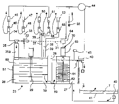
. Referring to Fig. 3, a system for producing a corrugating
adhesive in accordance with the present invention is shown.
A tank 25 has a mixing chamber 26 and a testing chamber
CA 02261661 1999-O1-27
WO 98/04643 _ PCT/US97/12490 - -
_
27, separated by a baffle 28 which provides an underflow from
the mixing chamber 26 into the testing chamber 27. The mixing
chamber contains a high shear agitator 29 for mixing the
various adhesive ingredients together. A viscosity sensor 30
5 is located within the testing chamber for determining the
adhesive viscosity.
To the mixing chamber are added the various ingredients
used to produce the corrugating adhesive 7. Each of these is
metered as a liquid, slurry or paste in a proportional fashion
10 to the mixing chamber. This may be done by using metering
pumps associated with each individual feed stream, by using a
microprocessor controller with associated flow control valves
or other means known or available to those skilled in the art.
The viscosity sensor 30 sends a control signal 31 to a diverter
valve 32 to adjustably split the flow rate of a raw slurry
stream 33 which is thus controllably either admixed with a
basic agent 34 in a mixing tee 35 so as to increase or decrease
gelling of the starch, or sent directly into the mixing
chamber. In other words, for a particular formula, the
diverter valve is fed a predetermined amount of raw starch
slurry, with the raw slurry stream fed in whole or in part to
either the mixing tee or the mixing chamber, depending on the
viscosity of adhesive produced.
A portion 35a of the mixing tee is of sufficient length to
allow interaction of the mixed streams before addition to the
CA 02261661 1999-O1-27
WO 98/04643 PCTIUS97/12490 - - -
11
mixing chamber. No mechanical mixing is required, because the
low volumes assure thorough intermixing and no agglomeration
occurs, thus a low volume smooth paste is formed. This portion
35a need be nothing more sophisticated than a short length of
pipe, to provide some residence time. Generally, the
ingredients react near instantaneously, though up to about five
seconds of residence time should be provided.
The remaining components, identified as streams 36,
additionally raw slurry, 37, water, 38, a boron-containing
compound and 39, a waterproofing agent, are all added as needed
with a particular recipe, in proportion to the amount of raw
slurry which is fed to the diverter valve or the amount of
basic agent supplied to the mixing chamber. The total rate of
addition of all the components to the mixing chamber
corresponds substantially to the rate of uptake of the adhesive
onto the corrugating flutes.
The raw starch slurry stream 36 is provided to reduce the
amount of raw slurry fed to the diverter valve, so as to
provide a good measure of control of the portion fed to the
mixing tee, though it is possible to feed all the raw slurry to
the diverter valve. Similarly water stream 37 may or may not
be needed, depending on the particular recipe chosen, as the
water is added in combination with the raw starch slurry. The
boron compound is a required ingredient, though the
waterproofing stream is clearly optional. Whatever combination
CA 02261661 1999-O1-27
WO 98/04643 _ PCT/US97/12490 - -
12
of ingredients are chosen, these are all fed proportionally and
continuously to the mixing chamber, as described above.
The size of the mixing chamber may range from 1 to 3 times
the per minute volume flow of all incoming ingredients, i.e.,
if the combined ingredient flows add up to about 20 LPM, the
size of the mixing chamber may be from about 20 to 60 liters.
The take up of the adhesive will vary depending on the
equipment used, product to be produced, i.e., single facer or
double backer, (one vs. two pans), etc. However, the overall
rates are in the range of about 1.5 to about 30 liters per
minute, corresponding roughly to corrugator speeds of up to
about 400 m/min. Consequently, a mixing chamber size of from
about 1.5 to 90 liters may be used, with about 20 to 60 liters
preferred. It should of course be understood that with the
inventive system, being of small modular construction, several
units can be distributed about the facility, for example one
unit each can serve a single pan as opposed to using a larger
unit serving several pans.
The size of the testing chamber is sufficient to
accommodate the viscosity sensing device and to provide at
least a small reservoir for remixing the recycled adhesive from
the corrugator pan to provide a uniform mix. Thus, the testing
chamber size may be in the range of from about 2.5 to 90
liters, though the size is not critical and it may vary
depending on the needs of a facility. To accommodate a typical
CA 02261661 1999-O1-27
WO 98/04643 _ PCT/US97/12490 - - -
13
viscosity sensor, a testing chamber of about 20 to 60 liters
would be used. Consequently, the total vessel size, with both
chambers can range from 3.8 to about 115 liters.
Referring again to Fig. 3, the testing chamber 27 has an
overflow outlet 40 which delivers adhesive to a corrugator pan
41. The level of adhesive 7 must remain relatively stable, and
excess adhesive is removed through an overflow pipe 42 for
return to the testing chamber 27. A liquid level sensor 43 is
located in the testing chamber which communicates with or
includes a controller 44. The controller 44 temporarily halts
all the in flowing streams when the level is high, reinitiating
the flows when the level drops back below the high point, or to
a preselected low level setting.
It is common to use a high recycle rate to keep the
adhesive from becoming too hot in the pan. A rate of two or
more times the uptake rate is not uncommon, and the invention
is adaptable to such a system as the recycled adhesive is
readily blended with fresh adhesive in the test chamber. Of
course, systems which use no recycle can also be accommodated.
Thus, the invention is not limited by such variations.
The particular ingredient feed means will now be
described. Referring still to Fig. 3, the apparatus for
producing corrugating adhesive has the stream of basic agent 34
fed to the mixing tee 35 at a metered flow rate. In this
embodiment of the invention, a pneumatically operated piston 45
CA 02261661 1999-O1-27
WO 98/04643 . PCT/US97/12490 - -
14
communicates with a fill piston 46 which draws a precise volume
of basic agent, from a storage tank (not shown) during a fill
stroke of the piston. This precise volume of basic agent is
then injected into the mixing tee during the downstroke of the
piston 46.
A stream of raw slurry 33 is correspondingly metered,
using a pneumatically operated piston 47 aid a fill piston 48,
to the diverter valve, with the strokes coordinated to provide
a proportioned mixture in the mixing chamber, though the amount
actually fed to the mixing tee will vary, as the diverter valve
32 is used to adjust the flow of raw slurry sent to the mixing
tee to adjust the viscosity of the adhesive, as will be
discussed further below.
An important advantage of the invention is that the
ingredients remain separated prior to entering the mixing
chamber, which increases storage life. These ingredients,
including the raw starch slurry, may be stored at room
temperature and require minimal attention.
For the inventive system, each stream must be in liquid,
slurry or paste form. This requires preparation of the raw
slurry by mixing starch with water. Also, the boron containing
compound must be admixed to form a slurry and then treated to
form a paste (i.e. containing thoroughly gelatinized starch) as
these compounds are generally insoluble in water. When
formulated with a paste, dispersion of the boron is maintained.
CA 02261661 1999-O1-27
WO 98/04643 _ PCT/US97/12490 - -
In a preferred embodiment, the boron containing compound is
admixed with a portion of starch paste, sufficient to provide a
flowable material with the boron containing compound uniformly
distributed in the paste. For example, a 2-5$ by weight dry
5 content starch paste can be prepared and the compound added to
it, the compound comprising from about 5 to 25~ more preferably
about 15 to 25~ by weight of the paste. The amount of raw
starch provided with the compound is compensated for in the
adhesive by reducing the amount of raw slurry added in stream
10 33 or 36.
Raw slurry 36, water 37 and the boron containing
compound/slurry 38 are similarly metered into the mixing
chamber using pneumatic pistons 50, 51 and 52, respectively,
with associated fill pistons 53, 54 and 55 again with the
15 stroke rate and piston displacement volume coordinated and
controlled to correspond to the addition rate of the raw starch
stream 33 fed to the diverter valve, or to the basic agent
stream 34 to provide a desired formulation. Of course, various
formulations can be provided, by adjusting the stroke rate or
piston displacement of each ingredient. For example, an
adhesive having a range of starch content of from about 15-340
wt. can be provided by adjusting the rate of raw slurry
addition 36, using pistons 50 and 53.
It should be understood that there are numerous additives
which may or may not be required depending on the product
CA 02261661 1999-O1-27
WO 98/04643 _ PCT/US97/12490- -
16
produced and these can be supplied on an as needed basis to the
mixing chamber, thus minimizing additive costs while optimizing
their utilization. Here, a water resistance additive stream 39
is provided on an as needed basis by a metering pump 56 to the
mixing chamber.
The admixed ingredients then enter the mixing chamber,
where the high shear agitator 29 mixes the adhesive ingredients
thoroughly. The mixing and testing chambers are maintained at
a particular temperature using a steam jacket 57.
All of the controlled streams follow a defined path
through the mixing chamber, passing from an upper portion 58 of
the chamber, down around the agitator's propeller blades to a
bottom 59 of the chamber where the mixed ingredients then
travel under the baffle 28 into the testing chamber 27
illustrated by arrow 60.
The testing chamber contains the viscosity sensor 30,
which in this case, is a device which measures the resistance
to rotation of disks 61 mounted on a shaft 62 which are turned
by a motor 63 at a constant speed.
The amperage consumed by the motor increases or decreases
in an amount correlated to the viscosity of the adhesive. The
amperage reading is converted by a transducer 64 to generate
the control signal 31 which regulates the amount of raw starch
which is diverted to and combined with the basic agent by the
judicious opening/closing of the diverted valve 36, the
CA 02261661 1999-O1-27
WO 98/04643 _ PCT/US97/12490- - -
17
undiverted portion entering the mixing chamber. The more
starch that is diverted to the mixing tee, the higher the
. viscosity of the adhesive.
The level sensor 93 allows for an automatic start/stop of
the adhesive making process. Since all the streams are metered
together, it is relatively simple to halt the flows, as needed,
to conserve the ingredients, without fear of a loss in
properties, as the unmixed streams have a much longer storage
life than the mixed adhesive. With only a 3.8-115, more
preferably about 7-60 and most preferably about 20-30 liters
holdup in the system, wastage is reduced substantially, capital
costs are reduced and adhesive properties optimized in
accordance with the present invention.
Before describing further the apparatus of the invention,
it is necessary to review the ingredients and properties of
corrugating adhesives.
Starch is the raw material for the corrugating adhesive,
and this is preferably obtained from corn or wheat. The starch
is usually obtained as a granular white powder.
Each starch granule is an organized tightly packed rigid
agglomeration of polymeric starch molecules held together by
intermolecular forces. These bonds can be disrupted with
thermal, mechanical or chemical energy. For starch to become
an adhesive, these bonds must be disrupted so as loosen the
individual molecules from one another as completely as
CA 02261661 1999-O1-27
WO 98/04643 - PCT/US97/12490 - -
18
possible.
When starch is heated in the presence of water, the bonds
weaken which allow the introduction of water into the spaces
between the starch molecules. This gradually increases the
S volume of the granule. This absorption is manifested as an
increase in viscosity. Eventually, however, the continuing
application of heat causes the swollen granules to burst
releasing their constituent molecules as well as captured
water, thereby causing an abrupt decrease in viscosity. This
is known as the gel point. For corn starch, this takes place
at about 74°C.
If a basic agent such as sodium hydroxide is added to the
slurry, the gel point can be reduced to lower temperatures
which can be determined and controlled by providing an
appropriate ratio of starch to water to sodium hydroxide.
Uniform dispersion is of course quite important to obtaining
the proper properties for the adhesive. For example, if during
the mixing of the ingredients, agitation were inefficient, high
concentrations of sodium hydroxide might occur in some spots,
which might thereby cause preferential gelling of some granules
but not others, with such a preferential gelling causing what
is known as "fisheyes". Consequently, vigorous mechanical
shearing is necessary to disrupt the bonds and to determine
accurately the true level of the viscosity of the adhesive,
that is, one that is related mainly to the amount of starch
CA 02261661 1999-O1-27
WO 98104643 PCT/US97/12490 - -
19
which is dispersed, at the gel temperature. However, it is
difficult to assure uniform dispersion because of the high
viscosity before gelation occurs.
Viscosity is a prime consideration for a optimized
corrugating adhesive, as it is directly related to controlling
how, where and how much of the adhesive is placed on the
corrugated sheet as it is contacted with the adhesive on the
roll.
The adhesive bond is formed by driving off most of the
water in the adhesive so as to allow the starch molecules to
attach themselves to one another and to the fibers of the
sheet. To minimize drying time, it is necessary that the
amount of water in the formulation be kept to a minimum. At
these minimum levels, if all the necessary starch were to be
IS dispersed in a single batch, the result would be a paste too
viscous to handle. Consequently, it has been necessary to
prepare the adhesive by dispersing only a portion of the starch
in all the water to achieve a slurry of manageable viscosity,
this portion being called the carrier and serving as a medium
in which the raw undispersed major portion of starch is
suspended and carried to the corrugator where it is heated by
the paper itself. Because the heat available is limited, the
time allowed is very short for the adhesive process to proceed
and therefore sodium hydroxide is included in the formulation
to lower the gel point of the adhesive to between about
CA 02261661 1999-O1-27
WO 98/04643 PCT/US97/12490 - - -
59-65°C .
If the gel point is too low, there is a possibility of
gelling the raw portion of the starch by heat given off in the
equipment before the adhesive is applied to the sheet. Also,
5 there is a limit to the amount of water that can be removed
from the formulation to speed drying, since it could be driven
off before the raw starch has a chance to disperse.
The starch may be either modified or unmodified, a
modified starch being treated to enhance its bonding qualities
10 such as to provide a stronger bond or to provide fast setting
or to adjust its viscosity stability over time. While of
higher cost, the cost is offset by making possible faster
corrugator speeds and minimizing the variation in adhesive
viscosity. Typically, the modified starches are used in the
15 carrier portion of the paste, the raw portion being made of
unmodified starch. However, many plants use unmodified starch
for both components of the formulation. The raw stored starch
slurry used with the invention typically comprises up to 38~
and more preferably about 25 to 38o by weight of starch. A
20 high concentration of starch is preferred because this allows
for subsequent dilution to the working concentration of the
adhesive in the inventive apparatus.
Water is another ingredient and this may be either fresh
water or recycled water, more commonly known as Flexo or
machine wash water which had been used to wash equipment in the
CA 02261661 1999-O1-27
WO 98/04643 - PCT/US97/12490 - - -
21 -
facilities and therefore it may contain inks or other
components which may effect viscosity. Since the apparatus of
the invention corrects for viscosity changes, these as well as
water of varying pH can be used without any treatment steps.
The next ingredient is a strong basic agent, with sodium
hydroxide preferred. Of course other basic agents may be used.
Sodium Hydroxide may be obtained as flake, granule or powder or
as a 50$ solution, and this is preferably diluted to about 2 to
15~, and more preferably, to about 5~ wt. dry content. The
degree of dilution is related to the volumetric proportion of
each ingredient.
A boron containing compound such as sodium borate or boric
acid, is typically used to adjust the body, tackiness and other
functional properties of the adhesive. Other additives may be
included which serve to adjust properties, or to produce
particular products, the most common additive being one which
increases the water resistance of the corrugated board.
An important consideration in the preparation of a
corrugating adhesive is that it has a tendency to age which
makes the time between preparation 'and application critical to
obtaining consistent properties. For example, the viscosity of
the adhesive is subject to change by reason of mechanical
shearing, which occurs through pumping or agitation of the
mixture, through temperature changes, biological spoilage,
additive reactions and moisture loss.
CA 02261661 1999-O1-27
WO 98/04643 _ PCT/US97/12490 - - .
22 _
Referring to Fig. 4, an enlarged view of the piston
metering apparatus usable with the present invention is shown.
However, it would be understood by those skilled in the art
that there are numerous devices and systems available both
commercially and technically for providing the coordinated
proportioned or metered stxeams, and the invention is not
limited to a piston type arrangement.
A pneumatic piston assembly 65 has a cylinder 66 in which
a piston 67 is movable. The piston moves in response to a
pressure differential imposed by a valve 68 which supplies air
to either side of the piston. When air is supplied through
line 69, the piston moves upward and when supplied through line
70, the piston moves downward.
The piston is connected to a shaft 71 which extends to a
fill piston 72 located within a cylinder 73. A pair of check
valves 74(a)and 74(b) determine the flow of an ingredient,
through an inlet 75 and an outlet 76. The cylinder has a vent
77 to allow displacement of the piston without resistance.
Since the two pistons are joined together, an upward
movement of piston 67 pulls piston 72 such that an ingredient
is drawn into the cylinder 73. A downstroke then discharges
the ingredient through the outlet 76.
As also shown, a single pneumatic piston 78 is connected
to two fill pistons 79 and 80 so as to allow precise metering
of a raw slurry and a basic agent to the mixing chamber. The
CA 02261661 1999-O1-27
WO 98!04643 _ PCT/LTS97/12490
23
ratio of these two ingredients can be varied using an
adjustable stop 82 with an adjustable yoke 83. A diverter
valve 84 is used to bypass a portion or all of the raw slurry
in response to a control signal from the viscosity sensor, the
diverted raw slurry entering a mixing tee 81, where the basic
agent and raw slurry are mixed together.
CA 02261661 1999-O1-27
WO 98/04643 - PCT/US97/12490 - - -
24 -
EXAMPLE
With reference to Fig. 5, a test was performed to
establish that the use of controlled continuous streams could
produce a satisfactory corrugating adhesive.
A tank 85 containing a high shear variable speed agitator
86, a temperature sensor 87 and a temperature controller 88 was
fed ingredients using graduated syringes. A motor speed
indicator 89 and amperage indicator 90 were used with a speed
adjuster 91 to control the agitator. The temperature
controller 88 controlled heating tape 92 to adjust the tank
temperature, indicated on a gauge 93. The tank had a drain
valve 94.
The object of the tests was to prove the feasibility of
constructing a system for the continuous preparation of starch
based corrugating adhesive. In such a system the finished
adhesive consumed by the corrugator pans) is immediately
replenished with freshly made adhesive at a rate of production
(gpm) equal to the rate of consumption. Moreover, the system
prepares the adhesive with accurate ingredient proportions,
controlled temperature, and with high agitational shear to
control viscosity.
Procedure (for carrier type adhesive)
To simulate continuous operation, the tests can only start
if the tank is already filled with adhesive.
CA 02261661 1999-O1-27
WO 98/04643 _ PCT/US97/12490 - -
A tank is filed with 1700 cc of previously prepared
adhesive with the proper portions of ingredients, adjusted to
_ 42°C. Viscosity is approximately 55 sec Stein Hall cup which
is a middle value of the 20 sec to 70 sec range encountered in
5 industry.
100 cc of adhesive is drained out through the drain valve.
Then a raw portion of slurry (38~ dry content) is syringed into
the tank. A carrier paste was farmed using 38~ dry content raw
starch slurry and 5.3$ dry content sodium hydroxide solution
10 which are also syringed into the tank. These two may be joined
at the mixing tee before entering the tank to maintain or
increase viscosity or syringed separately into the tank to
decrease viscosity. A water portion is syringed into the tank,
if required. Borax is also syringed into the tank, a borax mix
15 having been made up of 10 grams of dry borax admixed with 50 cc
of 2-5o dry content raw slurry, formulated as a paste.
After an initial decrease in temperature, all ingredients
being at room temperature, heat is applied to the side of the
tank automatically to adjust the temperature to 42°C in 2 min.
20 An initial upset in viscosity is eventually stabilized in 4
min. 100 cc of adhesive is drained, and the process is
repeated.
Description of the tests performed (for carrier type paste)
All ingredients were drawn from their respective storage
CA 02261661 1999-O1-27
WO 98/04643 _ PCT/US97/12490 - -
26
containers, calculated by weight, i.e. dry weight per total
weight as a percentage.
All temperature and viscosity readings were taken after
the system had reached equilibrium operating conditions. The
S gelatinization temperature of the samples made was periodically
checked and found to be in the 58 - 60°C range.
Test A For final paste @ 33~ cone , @ 42°C, unmodified corn
starch.
a. Prepare starting batch having 1700cc, 33~ cone ,
48°C.
(1301cc raw starch; 122 cc carrier starch; 258cc
caustic; l9cc borax)
Viscosity: 0.54 amp (51 - 53 sec SH)
b. Remove 100cc through drain valve.
Replenish with 76.5cc raw directly into tank
7.2cc carrier through mixing tee
15.2cc caustic through mixing tee
l.lcc borax directly into tank
0.0 water
Momentarily motor load to 0.58 amp, temp. to 41°C.
Equilibrium reached in 4 min.
Viscosity: 0.54 amp (51 - 53 sec SH)
c. Repeat step b three times.
Viscosity: 0.54 amp (51 - 53 sec SH)
CA 02261661 1999-O1-27
WO 98/04643 _ PCT/US97/12490 - -
27
d. Remove 100cc through drain valve.
Replenish with: 75.0cc raw directly into tank
8.7cc carrier through mixing tee
15.2cc caustic through mixing tee
l.lcc borax directly into tank
Momentarily motor load to 0.61 amp, temp, to 41°C.
Equilibrium reached in 4 min.
Viscosity: 0.57 amp (69 - 71 sec SH)
e. Repeat step d three times.
Viscosity: 0.60 amp (83 - 85 sec SH)
f. Remove 100 cc through drain valve.
Replenish with: 76.6cc raw directly into tank
7.2cc carrier directly into tank
15.2cc caustic directly into tank
l.lcc borax directly into tank
0.0cc water
Momentarily motor load to 0.58 amp, temp. to 41°C.
Equilibrium reached in 3 min.
Viscosity: 0.58 amp (76 - 78 sec SH)
g. Repeat step f three times.
Viscosity: 0.47 amp (32 - 34 sec SH)
I. Test discontinued.
Test B For final paste @ 18o cone , @ 42°C, unmodified
corn starch.
CA 02261661 1999-O1-27
WO 98/04643 _ PCT/US97/12490 -
28
a. Prepare starting batch 1700cc,
18o cone , 42C.
(599cc raw; 139 cc carrier; 178cc
caustic; llcc
borax; 778cc water)
Viscosity: 0.53 amp (48 - 50 sec
SH)
b. Remove 100cc through drain valve.
Replenish with 34.9cc raw directly into tank
8.2cc carrier through mixing tee
10.5cc caustic through mixing tee
0.7cc borax directly into tank
45.8cc water directly into tank
Momentarily motor load to 0.55 amp, temp. to 41C.
Equilibrium reached in 4 Min.
Viscosity: 0.53 amp (48 - 50 s ec SH)
c. Repeat step b three times.
Viscosity: 0.53 amp (48 - 50 s ec SH)
d. Remove 100cc through drain valve.
Replenish with: 33.4cc raw directly into tank
9.7cc carrier through mixing tee
10.5cc caustic through mixing tee
0.7cc borax directly into tank
45.7cc water directly into tank
Momentarily motor load to 0.58 amp, temp. to 41C.
Equilibrium reached in 4 min.
Viscosity: 054 amp (50 - 52 sec SH)
e. Repeat step d three times.
CA 02261661 1999-O1-27
WO 98/04643 _ PCT/US97/12490- -
29
Viscosity: 0.61 amp (88 - 90 sec SH)
f. Remove 100cc through drain valve.
Replenish with: 39.9cc raw directly into tank
8.2cc carrier directly into tank
10.5cc caustic directly into tank
0.7cc borax directly into tank
45.8cc water directly into tank
Momentarily motor load to 0.64 amp, temp. To 41°C.
Equilibrium reached in 4 Min.
Viscosity: 0.58 amp (78 - 80 sec SH)
g. Repeat step f three times.
Viscosity: 0.45 amp (28 - 30 sec SH)
I. Test discontinued.
Test C These two tests were identical to Tests A & B, except
that wheat starch was used for the carrier raw starch
Test D portion of the paste instead of corn starch. A
lesser proportion of caustic was employed. A
consistent viscosity product was achieved and the
results demonstrated the efficacy of the process in
controlling paste viscosity in a continuous system.
Test E These two tests were identical to Tests A & B, except
high amylose starch was used for the carrier portion
CA 02261661 1999-O1-27
WO 98/04643 _ PCT/US97/12490
Test F of the paste instead of corn starch. A lesser
proportion of carrier starch was employed. A
consistent viscosity product was achieved and the
results demonstrated the efficacy of the process in
controlling paste viscosity in a continuous stream.
These tests demonstrate the ability of the process to
produce final paste at concentrations ranging from 33~ starch
solids (tests A, C, E) to 18~ starch solids (tests B, D, F)
10 whose viscosity can be controlled over the entire range
required for corrugating applications.
The tests further demonstrate the ability to produce final
adhesive at a desired temperature by means independent of the
temperature of the incoming ingredients, which are at or near
15 ambient temperature.
Although not specifically tested, it is evident that the
gelatinization temperature can be controlled by variation of
the caustic borax portions, as is the practice in the industry,
and the throughput rate of the process can be controlled by the
20 proper adjustment of the flow rate of each ingredient while
maintaining their proportions.
Referring to Fig. 6, an alternative vessel 95 usable with
the present invention is shown. The vessel 95 has a mixing
chamber 96 and a testing chamber 97. However, an alternate
25 feed and baffle system is used, to alter the flow path through
CA 02261661 1999-O1-27
WO 98/04643 PCT/ITS97/12490 - -
31
these chambers.
Each of the feed streams 33, 34, 36, 37, 38 and 39 enter
the mixing chamber at a bottom end 98. As previously
discussed, the admixture is prepared in the mixing tee 35.
Instead of an underflow, here, a baffle 100 directs the
ingredients to overflow from the mixing chamber, as indicated
by an arrow 99. A second baffle 101 then requires the mixed
ingredients to enter the testing chamber, again with an
underflow, as indicated by arrow 60a.
This arrangement provides a constant level in the mixing
chamber, to promote uniform mixing of the ingredients, and to
keep the high shear agitator fully covered. Of course, there
are a number of other baffle arrangements available.
While preferred embodiments have been shown and described,
it will be understood by those skilled in the art that other
modifications can be made without varying from the scope of the
invention.
I claim: