Language selection

Search

Patent 2262157 Summary

Third-party information liability

Some of the information on this Web page has been provided by external sources. The Government of Canada is not responsible for the accuracy, reliability or currency of the information supplied by external sources. Users wishing to rely upon this information should consult directly with the source of the information. Content provided by external sources is not subject to official languages, privacy and accessibility requirements.

Claims and Abstract availability

Any discrepancies in the text and image of the Claims and Abstract are due to differing posting times. Text of the Claims and Abstract are posted:

  • At the time the application is open to public inspection;
  • At the time of issue of the patent (grant).
(12) Patent: (11) CA 2262157
(54) English Title: TREE FASTENER WITH SPLIT WINGS
(54) French Title: GOUJON D'ASSEMBLAGE A AILETTES FENDUES
Status: Expired and beyond the Period of Reversal
Bibliographic Data
(51) International Patent Classification (IPC):
  • F16B 13/04 (2006.01)
  • F16B 19/00 (2006.01)
(72) Inventors :
  • MEYER, CHARLES (United States of America)
(73) Owners :
  • ILLINOIS TOOL WORKS INC.
(71) Applicants :
  • ILLINOIS TOOL WORKS INC. (United States of America)
(74) Agent: FINLAYSON & SINGLEHURST
(74) Associate agent:
(45) Issued: 2003-04-29
(22) Filed Date: 1999-02-16
(41) Open to Public Inspection: 1999-08-24
Examination requested: 1999-02-16
Availability of licence: N/A
Dedicated to the Public: N/A
(25) Language of filing: English

Patent Cooperation Treaty (PCT): No

(30) Application Priority Data:
Application No. Country/Territory Date
09/028,889 (United States of America) 1998-02-24

Abstracts

English Abstract


The tree fastener includes a shank, a head and wings on
first and second opposed sides of the shank. The wings are split
along the tool parting line into wing portions which extend from
the shank at different angles so that the spacing between wing
portions is one half the distance between successive wings.
Additionally, the wing portions are diagonally paired so that
wing portions on a first opposed side of the shank and a first
side of the tool parting line extend from the shank at the same
angle as wing portions on a second opposed side of the shank and
a second side of the tool parting line. Likewise, wing portions
on a second side of the shank and a first side of the tool
parting line extend from the shank at the same angle as wing
portions on a first side of the shank and a second side of the
tool parting line.


Claims

Note: Claims are shown in the official language in which they were submitted.

WHAT IS CLAIMED IS:
1. A tree fastener comprising:
a shank, having first and second opposed flat surfaces on
diametrically opposite sides of said shank;
a head formed on a first end of said shank;
a first set of wings, spaced at a predetermined
longitudinal distance extending from said first flat surface
and an identical set of wings extending from said second flat
surface, said wings each being split into a first wing portion
and a second wing portion, said first wing portion and said
second wing portion extending from said shank at different
angles.
2. The tree fastener of claim 1 wherein said different
angles are first and second angles whereby a distance between
said first wing portion and successive second wing portion is
substantially equal to one half of said predetermined
longitudinal distance.
3. The tree fastener of claim 2 wherein said wings are split
along a plane extending radially from a longitudinal axis of
said shank.
4. The tree fastener of claim 3 wherein said plane is formed
by a tool parting line.
5. The tree fastener of claim 4 wherein said first wing
portions are on a first side of said plane anti said second
wing portions are on a second side of said plane.
6. A tree fastener comprising:
a shank, first and second opposed sides of said shank;
a head formed on a first end of said shank;
7

wings, spaced at a predetermined longitudinal distance
extending from said first and second opposed sides of said
shank, said wings being split into a first wing portion and a
second wing portion, said first wing portion and said second
wing portion extending from said shank at first and second
angles, whereby a distance between said first wing portion and
successive second wing portion is substantially equal to one
half of said predetermined longitudinal distance;
wherein said wings are split along a plane extending
radially from a longitudinal axis of said shank and said first
wing portions are on a first side of said plane and said
second wing portions are on a second side of said plane, and
wherein said first wing portions on said first opposed
side of said shank and said second wing portions on said
second opposed side of said shank extend from said shank at
said first angle and wherein said second wing portions on said
first opposed side of said shank and said first wing portions
on said second opposed side of said shank extend from said
shank at said second angle.
7. The tree fastener of claim 6 wherein said head is
substantially conically shaped with a circular base, said
circular base having a periphery.
8. The tree fastener of claim 7 wherein said first and
second opposed sides of said shank are indented from a
periphery of said circular base.
9. The tree fastener of claim 8 wherein said first and
second opposed sides of said shank include peripheral portions
which are at least partially coextensive with said periphery
of said circular base.
8

10. The tree fastener of claim 9 wherein said shank has a
generally H-shaped cross section formed by said first and
second opposed sides and a cross member therebetween.
11. The tree fastener of claim 10 wherein the tree fastener
is formed of molded plastic.
9

Description

Note: Descriptions are shown in the official language in which they were submitted.


CA 02262157 1999-02-16
3029-52 TREE FASTENER WITH SPLIT WINGS
BACKGROUND OF THE INVENTION
Field of the Invention
The invention pertains to a tree fastener with wings which
are split along the tool parting line and offset half of the
branch spacing distance.
Description of the Prior Art
Tree fasteners with radially extending branches or wings for
insertion into apertures in sheet metal and similar structures
are known in the prior art. However, prior art tree fastener
designs have a minimum branch spacing dictated by tooling
constraints. The branch spacing governs the amount of play when
the fastener is installed. If the panel thickness is such that
one set of branches is unable to clear the panel, then the tree
fastener is retained by the next lower set of branches. This
creates play and rattles which are unacceptable in motor vehicles
and similar applications. Ideally, the branches would always be
located to clear the panels precisely, but thickness variations,
burrs and manufacturing tolerances prevent the ideal situation.
Some prior art designs rely on flexible arms to compensate for
this play and these intolerances, but many times design
constraints prevent the use of flexible arms.
Examples of prior art tree fasteners are disclosed in U.S.
Patent No. 5,468,108 entitled "Spiral Flex Tree Fastener" issued
on November 21, 1995 to Sullivan et al.: U.S. Patent No.
5,039,267 entitled "Tee Tree Fastener" issued on August 13, 1991

CA 02262157 2002-05-06
to Wollar; U.S. Patent No. 4,776,739 entitled "Plastic Drive
Fastener" issued on October 11, 1988 to Hamman; U.S. Patent
No. 4,728,238 entitled "Plastic Drive Fastener" issued on
March 1, 1988 to Chisholm et al.; U.S. Patent No. 4,402,641
entitled "Self Centering Fastener" issued on ~;eptember 6, 1983
to Arff; and U.S. Patent No. 4,392,278 entitled "Fastener"
issued on July 12, 1983 t:o Mugglestone.
SUNDRY OF THE INVENTION
Accordingly, the invention seeks to provide a tree
fastener with an increased accuracy of fit.
Further, the invention seeks to provide a tree fastener
which decreases the amount of play when installed.
Still further, the invention seeks to provide a tree
fastener with a decreased branch spacing and a. subsequent
finer increment of fit while maintaining its strength and one
which does not necessitate substantial changes in the tooling
constraints of present designs.
The invention in one broad aspect provides a tree
fastener comprising a shank, having first and second opposed
flat surfaces on diametrically opposite sides of the shank, a
head formed on a f first end of the shank, and a. f first set of
wings, spaced at a predetermined longitudinal distance
extending from the first flat surface and an identical set of
wings extending from the second flat surface. The wings are
each split into a first wing portion and a~second wing
portion, the first wing portion and the second wing portion
extending from the shank at different angles.
More particularly, the invention provides a tree fastener
design wherein the branches are split at the tool parting line
and are offset by one half of the branch spacing
2

CA 02262157 1999-02-16
distance. This creates a finer increment, eliminating the need
for an overdrive feature. Tool integrity is maintained because
this design does not result in "thin steel" conditions. The
offset or staggered split branches result in a finer increment
thereby minimizing play, without sacrificing the removal
strength. Additionally, pairing the split branches diagonally
prevents the tree fastener from "walking" out of the aperture
under repeated loading or vibration.
BRIEF DESCRIPTION OF THE DRAWINGS
Further objects and advantages of the invention will become
apparent from the following description and claims, and from the
accompanying drawings, wherein:
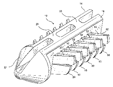
Figure 1 is a perspective view of the tree fastener of the
present invention.
Figure 2 is a side plan view of the tree fastener of the
present invention, further showing a side view of the split wings
or branches of the tree fastener.
Figure 3 is a side plan view of the tree fastener of the
present invention, further showing an end view of the split wings
or branches of the tree fastener.
Figure 4 is a front plan view, partially in phantom, of the
tree fastener of the present invention.
3

CA 02262157 1999-02-16
DETAILED DESCRIPTION OF THE PREFERRED EMBODIMENT
Referring now to the drawings in detail wherein like
numerals refer to like elements throughout the several views, one
sees that Figure 1 is a perspective view of tree fastener 10 of
the present invention. Tree fastener 10 is formed of molded
plastic or a similar material. As shown in Figures 1-4, tree
fastener 10 includes a longitudinal shank 12 of generally H-
shaped cross section. The H-shaped cross section is formed of
opposed lateral sides 14, 16 and longitudinal cross member 18.
Additionally, opposed lateral sides 14, 16 are spaced by
transverse supports 20, 22. The outer ends 24, 26 and 28, 30 of
opposed lateral sides 14, 16, respectively, are coextensive with
a portion of the circumference of the circular base 31 of conical
head 32.
As shown in Figures 1 and 4, the planar exterior walls 34,
36 of opposed lateral sides 14, 16, respectively, are inwardly
recessed from the circular base 31 of conical head 32 thereby
forming detent ledges 38, 40, respectively, on the underside of
circular base 31 where circular base 31 joins longitudinal shank
12. Additionally, wings or branches 42, 44 are formed on planar
exterior walls 34, 36 of opposed lateral sides 14, 16 and extend
away from planar walls 34, 36 at an inclined angle extending
generally outward and to the rear 46 of longitudinal shank 12.
Wings 42 are split along the tool parting line 48 so that
wings 42 form wing halves 50, 52. Similarly, wings 44 are split
along the tool parting line 48 so that wings 44 form wing halves
4

CA 02262157 1999-02-16
54, 56. The tool parting line 48 is formed on the plane where
the two halves of the mold (not shown) meet and extends radially
outward from the longitudinal axis of shank 12.
The angle of inclination of wing halves 50, 56 from shank 12
is varied from the angle of inclination of wing halves 52, 54
from shank 12 so that the spacing 58 (see Figure 2) of each wing
half 50 to each successive wing half 52 (or each wing half 54 to
each successive wing half 56) is equal to one half of the spacing
60 between wings 42. Spacing 60 is likewise the spacing between
successive wing halves of like indicia 50, 52, 54 or 56. This
staggered configuration of wing halves 50, 52, 54, 56 allows tree
fastener 10 to be manufactured with tooling for the larger
increment commensurate with spacing 60 but results in a tree
fastener 10 with an effective increment commensurate with the
finer spacing 58.
As illustrated in Figures 2, 3 and 4, each pair of wing
halves 50, 52 corresponds to a wing 42 and, likewise, each pair
of wing halves 54, 56 corresponds to a wing 44. Each wing 42 is
directly opposite from wing 44 across shank 12. For each pair of
opposed wings 42, 44, wing halves 52 and 54 are inclined a more
rearward angle than are wing halves 50 and 56. As illustrated in
Figure 3, this results in the matching of angles of inclination
of diagonally opposite wing halves 52, 54 and 50, 56. This
matching of inclination of diagonally opposite wing halves
minimizes the occurrence of the tree fastener 10 "walking" out of
an aperture under repeated loading or vibration.

CA 02262157 1999-02-16
In other words, the wing halves 50, 52, 54, 56 are
diagonally paired so that wing halves 50 on first planar wall 34
of shank 12 and a first side (i.e., the lower side from the
perspective of Figure 4) of the tool parting line 48 extend from
shank 12 at the same angle as wing halves 56 on second planar
wall 36 of the shank 12 and a second side (i.e., the upper side
from the perspective of Figure 4) of the tool parting line 48.
Likewise, wing halves 54 on second planar wall 36 of shank 12 and
a first side of the tool parting line 48 extend from shank 12 at
the same angle as wing halves 52 on a first planar wall 34 of
shank 12 and a second side of the tool parting line.
To use tree fastener 10, the conical head 32 of tree
fastener 10 is inserted into an aperture (not shown) which is
typically formed in a plurality of successive planar layers of
sheet metal to be joined. The wing halves 50, 52, 54, 56 engage
the sheet metal. The fine spacing of the wing halves provides
for a finer increment and more precise joining of the successive
layers.
Thus the several aforementioned objects and advantages are
most effectively attained. Although a single preferred
embodiment of the invention has been disclosed and described in
detail herein, it should be understood that this invention is in
no sense limited thereby and its scope is to be determined by
that of the appended claims.
6

Representative Drawing
A single figure which represents the drawing illustrating the invention.
Administrative Status

2024-08-01:As part of the Next Generation Patents (NGP) transition, the Canadian Patents Database (CPD) now contains a more detailed Event History, which replicates the Event Log of our new back-office solution.

Please note that "Inactive:" events refers to events no longer in use in our new back-office solution.

For a clearer understanding of the status of the application/patent presented on this page, the site Disclaimer , as well as the definitions for Patent , Event History , Maintenance Fee  and Payment History  should be consulted.

Event History

Description Date
Time Limit for Reversal Expired 2011-02-16
Letter Sent 2010-02-16
Grant by Issuance 2003-04-29
Inactive: Cover page published 2003-04-28
Inactive: Final fee received 2003-01-29
Pre-grant 2003-01-29
Notice of Allowance is Issued 2002-08-09
Letter Sent 2002-08-09
Notice of Allowance is Issued 2002-08-09
Inactive: Approved for allowance (AFA) 2002-07-30
Amendment Received - Voluntary Amendment 2002-05-06
Inactive: S.30(2) Rules - Examiner requisition 2001-12-10
Application Published (Open to Public Inspection) 1999-08-24
Inactive: Cover page published 1999-08-23
Inactive: IPC assigned 1999-03-31
Classification Modified 1999-03-31
Inactive: IPC assigned 1999-03-31
Inactive: First IPC assigned 1999-03-31
Inactive: Filing certificate - RFE (English) 1999-03-17
Filing Requirements Determined Compliant 1999-03-17
Application Received - Regular National 1999-03-16
Request for Examination Requirements Determined Compliant 1999-02-16
All Requirements for Examination Determined Compliant 1999-02-16

Abandonment History

There is no abandonment history.

Maintenance Fee

The last payment was received on 2003-02-11

Note : If the full payment has not been received on or before the date indicated, a further fee may be required which may be one of the following

  • the reinstatement fee;
  • the late payment fee; or
  • additional fee to reverse deemed expiry.

Please refer to the CIPO Patent Fees web page to see all current fee amounts.

Owners on Record

Note: Records showing the ownership history in alphabetical order.

Current Owners on Record
ILLINOIS TOOL WORKS INC.
Past Owners on Record
CHARLES MEYER
Past Owners that do not appear in the "Owners on Record" listing will appear in other documentation within the application.
Documents

To view selected files, please enter reCAPTCHA code :


To view images, click a link in the Document Description column. To download the documents, select one or more checkboxes in the first column and then click the "Download Selected in PDF format (Zip Archive)" or the "Download Selected as Single PDF" button.

List of published and non-published patent-specific documents on the CPD .

If you have any difficulty accessing content, you can call the Client Service Centre at 1-866-997-1936 or send them an e-mail at CIPO Client Service Centre.


Document
Description 
Date
(yyyy-mm-dd) 
Number of pages   Size of Image (KB) 
Cover Page 2003-03-26 1 48
Abstract 1999-02-16 1 26
Description 1999-02-16 6 232
Claims 1999-02-16 3 70
Drawings 1999-02-16 3 86
Cover Page 1999-08-23 1 40
Representative drawing 2001-11-23 1 17
Representative drawing 1999-08-23 1 12
Description 2002-05-06 6 244
Claims 2002-05-06 3 98
Courtesy - Certificate of registration (related document(s)) 1999-03-17 1 117
Filing Certificate (English) 1999-03-17 1 165
Reminder of maintenance fee due 2000-10-17 1 110
Commissioner's Notice - Application Found Allowable 2002-08-09 1 164
Maintenance Fee Notice 2010-03-30 1 171
Correspondence 2003-01-29 1 32